
Related Manuals for Miller Electric Spectrum 2050


Summary of Contents for Miller Electric Spectrum 2050
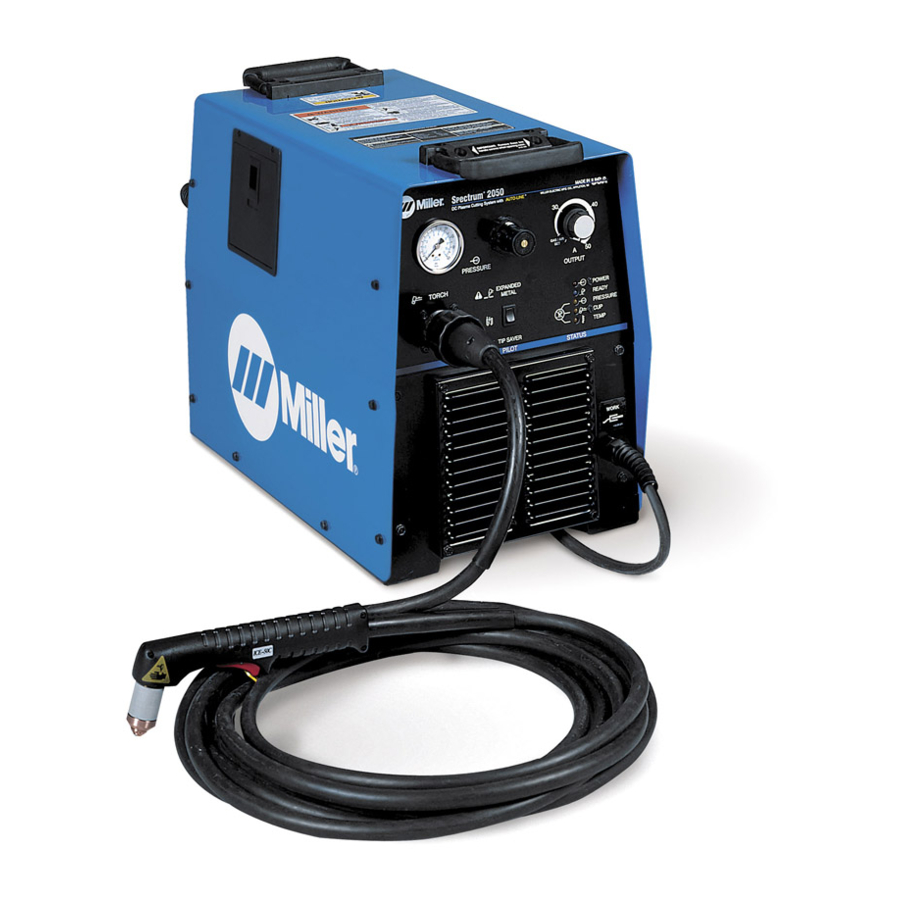
- Page 1 Spectrum 2050 Visit our website at www.MillerWelds.com OM-2220 190 444H November 1999 Processes Air Plasma Cutting and Gouging Description Air Plasma Cutter...
- Page 2 ISO 9001 Quality System Standard. service information for your particular model are also provided. Miller Electric manufactures a full line of welders and welding related equipment. For information on other quality Miller products, contact your local Miller distributor to receive the latest full line catalog or individual catalog sheets.
-
Page 3: Table Of Contents
SECTION 1 – SAFETY PRECAUTIONS - READ BEFORE USING 1-1. Symbol Usage 1-2. Plasma Arc Cutting Hazards 1-3. Additional Symbols For Installation, Operation, And Maintenance WARNING 1-4. Principal Safety Standards 1-5. EMF Information This product, when used SECTION 1 – CONSIGNES DE SÉCURITÉ – LIRE AVANT UTILISATION for welding or cutting, 1-1. -
Page 5: Section 1 - Safety Precautions - Read Before Using
SECTION 1 – SAFETY PRECAUTIONS - READ BEFORE USING 1-1. Symbol Usage Means Warning! Watch Out! There are possible hazards with this procedure! The possible hazards are shown in the adjoining symbols. Y Marks a special safety message. Means “Note”; not safety related. 1-2. -
Page 6: Arc Rays Can Burn Eyes And Skin
EXPLODING PARTS can injure. D On inverter power sources, failed parts can ex- plode or cause other parts to explode when power is applied. Always wear a face shield and long sleeves when servicing inverters. FLYING SPARKS can cause injury. Sparks and hot metal blow out from the cutting arc. -
Page 7: Additional Symbols For Installation, Operation, And Maintenance
1-3. Additional Symbols For Installation, Operation, And Maintenance HOT PARTS can cause severe burns. D Do not touch hot parts bare handed. D Allow cooling period before working on torch. MOVING PARTS can cause injury. D Keep away from moving parts such as fans. D Keep all doors, panels, covers, and guards closed and securely in place. -
Page 8: Principal Safety Standards
1-4. Principal Safety Standards Safety in Welding and Cutting, ANSI Standard Z49.1, from American Welding Society, 550 N.W. LeJeune Rd, Miami FL 33126 Safety and Health Standards, OSHA 29 CFR 1910, from Superinten- dent of Documents, U.S. Government Printing Office, Washington, D.C. 20402. -
Page 9: Section 1 - Consignes De Sécurité - Lire Avant Utilisation
SECTION 1 – CONSIGNES DE SÉCURITÉ – LIRE AVANT UTILISATION 1-1. Signification des symboles Signifie Mise en garde ! Soyez vigilant ! Cette procédure présente des risques de danger ! Ceux-ci sont identifiés par des symboles adjacents aux directives. Y Identifie un message de sécurité particulier. Signifie NOTA ;... - Page 10 D N’approchez pas le tube du chalumeau et l’arc pilote lorsque la gâchette est enfoncée. D Le câble de masse doit être pincé correctement sur la pièce à couper, métal contre métal (et non de telle sorte qu’il puisse se détacher), ou sur la table de travail le plus près possible de la ligne de coupage.
-
Page 11: Dangers Supplémentaires En Relation Avec L'installation, Le Fonctionnement Et La Maintenance
1-3. Dangers supplémentaires en relation avec l’installation, le fonctionnement et la maintenance DES PIECES CHAUDES peuvent pro- voquer des brûlures graves. D Ne pas toucher des parties chaudes à mains nues. D Laisser refroidir avant d’intervenir sur la torche. DES ORGANES MOBILES peuvent provoquer des blessures. -
Page 12: Information Sur Les Champs Électromagnétiques
1-5. Information sur les champs électromagnétiques Données sur le soudage électrique et sur les effets, pour l’organisme, des champs magnétiques basse fréquence Le courant de soudage ou de coupage passant dans les câbles de puis- sance crée des causera des champs électromagnétiques. Il y a eu et il y a encore un certain souci à... -
Page 13: Section 2 - Installation
SECTION 2 – INSTALLATION 2-1. Specifications NOTE For any single or three phase voltage from 208 V to 575 V, the Amperes Input at Rated Load Output is the same for 50 Hertz or 60 Hertz input power. For example, the amperes input for 230 V, 50 Hz, single-phase input power is 33 amperes. -
Page 14: Duty Cycle And Overheating
2-2. Duty Cycle and Overheating Three-Phase Input Power: 60% Duty Cycle 6 Minutes Cutting Overheating 2-3. Cutting Speed OM-2220 Page 10 4 Minutes Resting 5 Minutes Cutting Minutes Duty Cycle is percentage of 10 min- utes that unit can cut at rated load without overheating. -
Page 15: Selecting A Location
2-4. Selecting a Location Dimensions And Weight 70 lb (31.8 kg) Movement Location 18 in (460 mm) 24 in (610 mm) 12-1/2 in (318 mm) Y Do not move or operate unit where it could tip. 18 in (460 mm) 17 in (432 mm) Lifting Handles... -
Page 16: Connecting Work Clamp And Gas/Air Supply
2-5. Connecting Work Clamp and Gas/Air Supply From Gas/Air Supply Rear of Unit 2-6. Electrical Service Guide NOTE For any single or three phase voltage from 208 V to 575 V, the Amperes Input at Rated Load Output is the same for 50 Hertz or 60 Hertz input power. For example, the amperes input for 230 V, 50 Hz, single-phase input power is 33 amperes. -
Page 17: Extension Cord Data
50 Hz Models Input Voltage Input Amperes At Rated Output Max Recommended Standard Fuse Rating In Amperes Time-Delay Normal Operating 3 Min Input Conductor Size In AWG/Kcmil Max Recommended Input Conductor Length In Feet (Meters) Min Grounding Conductor Size In AWG/Kcmil Reference: 1999 National Electrical Code (NEC) 1 Consult factory for circuit breaker applications. -
Page 18: Connecting Input Power
2-8. Connecting Input Power Green Y Always connect grounding conductor first. = GND/PE OM-2220 Page 14 Green Green Tools Needed: 3/8 in 3/8 in input_2 3/96 - Ref. ST-144 221 / Ref. ST-070 399-C / ST-802 183 Check input voltage available at site. -
Page 19: Section 3 - Operation
SECTION 3 – OPERATION 3-1. Controls Gas/Air Pressure Gauge Gas/Air Pressure Control Output Control Use control to select cutting output in am- peres. Gas/air automatically flows at the set pressure. Use Gas/Air Set area of control range for set- ting gas/air pressure (see Section 3-2). Trouble Lights (see Section 4-2) Power Light Ready Light... -
Page 20: Setting Gas/Air Pressure
3-2. Setting Gas/Air Pressure Setting Gas/Air Pressure Place Output Control in Gas/Air Set Position Power Switch On 90–150 PSI Supply (620–1035 kPa) Set Controls Turn On Gas/Air Supply Output Control Power Switch Place controls as indicated above. Only gas/ OM-2220 Page 16 Rear of Unit Requires Set To 70 PSI... -
Page 21: Sequence Of Operation
3-3. Sequence of Operation Do not clean torch by hitting it against a hard surface. Hitting hard surfaces can damage torch parts and stop proper opera- tion. Install & Put On Personal Connect Safety Equipment Equipment Begin Cutting EXAMPLE Of Cutting Operation Place drag shield on edge of metal, or allow correct standoff distance –... -
Page 22: Section 4 - Maintenance & Troubleshooting
SECTION 4 – MAINTENANCE & TROUBLESHOOTING 4-1. Routine Maintenance Check Torch Tip, Electrode, And Shield Cup Replace Cracked Parts Check Gas/Air Hose OM-2220 Page 18 Y Disconnect power before maintaining. Each Use Every Week Check Shield Cup Shutdown System 3 Months Replace Unreadable Labels... -
Page 23: Trouble Lights
4-2. Trouble Lights Difficulty establishing pilot arc may indicate consumables need to be cleaned or replaced. 4-3. Checking Shield Cup Shutdown System Power must be reset whenever the cup shutdown system is activated. Always turn Off power when changing or checking consumables. Pressure Light Lights if gas/air pressure is below 40 PSI (276 kPa). -
Page 24: Troubleshooting
4-4. Troubleshooting Trouble No pilot arc; difficulty in establishing an Clean or replace worn consumables as necessary (see torch Owner’s Manual). arc. Check for damaged torch or torch cable (see torch Owner’s Manual). No cutting output; Power light off; Place Power switch in On position. Trouble lights off;... - Page 25 Notes OM-2220 Page 21...
-
Page 26: Section 5 - Electrical Diagram
SECTION 5 – ELECTRICAL DIAGRAM Figure 5-1. Circuit Diagram For Power Source OM-2220 Page 22... - Page 27 197 286-A OM-2220 Page 23...
-
Page 28: Section 6 - Parts List
SECTION 6 – PARTS LIST Hardware is common and not available unless listed. OM-2220 Page 24 Figure 6-1. Main Assembly ST-802 184-E... - Page 29 Item Dia. Part Mkgs....187 782 ......126 416 .
- Page 30 Notes...
- Page 31 Warranty Questions? Call LIMITED WARRANTY – Subject to the terms and conditions below, Miller Electric Mfg. Co., Appleton, Wisconsin, warrants 1-800-4-A-MILLER to its original retail purchaser that new Miller equipment sold for your local after the effective date of this limited warranty is free of defects in material and workmanship at the time it is shipped by Miller.
-
Page 32: Options And Accessories
Parts) Circuit Diagrams Welding Process Handbooks File a claim for loss or damage during shipment. 2000 Miller Electric Mfg. Co. 6/00 Miller Electric Mfg. Co. An Illinois Tool Works Company 1635 West Spencer Street Appleton, WI 54914 USA International Headquarters–USA USA Phone: 920-735-4505 Auto-Attended USA &...