Metrologic MS6520 Cubit Installation And User Manual
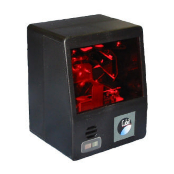
Cubit series omnidirectional bar code scanner
Hide thumbs
Also See for MS6520 Cubit:
- Installation and user manual (44 pages) ,
- Service manual (46 pages)

Related Manuals for Metrologic MS6520 Cubit


Summary of Contents for Metrologic MS6520 Cubit
- Page 1 METROLOGIC INSTRUMENTS, INC. IS6520/MS6520 Cubit™ Series Omnidirectional Bar Code Scanner Installation and User’s Guide...
- Page 3 Suzhou, China 215021 Copyright © 2000 by Metrologic Instruments, Inc. All rights reserved. No part of this work may be reproduced, transmitted, or stored in any form or by any means without prior written consent, except by reviewer, who may quote brief passages in a review, or provided for in the Copyright Act of 1976.
- Page 4 Printed in USA March 2000...
-
Page 5: Table Of Contents
Introduction... 1 Scanner and Accessories... 2 Quick Start ... 3 Installing the IS6520-41/MS6520-41 to the Host System ... 4 Installing the IS6520-47/MS6520-47 to the PC ... 5 Disconnecting the PowerLink Cables from the Scanner ... 7 Scanner Parts ... 8 Mounting Holes... - Page 6 ABLE OF ONTENTS Appendix C Scanner Pinout Connections... 32 Cable Connector Configurations ... 32 Appendix D Warranty and Disclaimer ... 35 Appendix E Notices... 37 Appendix F Patents... 39 Index ... 40...
- Page 7 Printer Note: Leave page blank...
-
Page 8: Introduction
PowerLink quick-disconnect cables. The modular design of Cubit allows the unit to be tailored to meet the needs of a specific application. As a retail scanner, the MS6520’s user-friendly mounting bracket bolts securely to the countertop or wall for fixed-mount scanning. Cubit’s small size and aggressive scan pattern make it ideal for convenience, sporting goods, apparel and toy/hobby stores. -
Page 9: Scanner And Accessories
CANNER AND CCESSORIES The following is a list of the parts included in the IS6520/MS6520 Kit. Cubit™ IS6520/MS6520 - Omnidirectional Scanning Engine PowerLink Power Supply - AC to DC Power Transformer. Regulated 5.2 VDC @ 650 mA output. One of the following may be included: 120 VAC United States –... -
Page 10: Quick Start
TART Connect the 10-pin RJ45 male connector into the jack on the Cubit™ IS6520/MS6520. You will hear a ‘click’ when the connection is made. Connect the L-shaped plug of the power supply into the power jack on the PowerLink cable. -
Page 11: Installing The Is6520-41/Ms6520-41 To The Host System
Turn off the host system. Connect the 10-pin RJ45 male connector into the jack on the Cubit™ IS6520/MS6520. You will hear a ‘click’ when the connection is made. Note: If the Cubit™ IS6520 is receiving power from the host system, skip to step #5. -
Page 12: Installing The Is6520-47/Ms6520-47 To The Pc
Turn off the PC. Connect the 10-pin RJ45 male connector into the jack on the Cubit™ IS6520/MS6520. You will hear a ‘click’ when the connection is made. Connect the L-shaped plug of the power supply into the power jack on the PowerLink cable. - Page 13 To maintain compliance with standard CSA C22.2 No. 950/UL 1950 and norm EN 60950, the power source should meet applicable performance requirements for a limited power source.
-
Page 14: Disconnecting The Powerlink Cables From The Scanner
ISCONNECTING THE OWER ABLES FROM THE Before removing the cable from the scanner, Metrologic recommends that the power on the host system is off and the power supply has been disconnected from the PowerLink cable. • Ž & • Œ... -
Page 15: Scanner Parts
The LEDs are also used as diagnostic indicators and mode indicators. Output Window Laser light emits form this aperture. Powerlink Cable The IS6520/MS6520 scanner has a 10-pin modular jack. The 10-pin modular plug on the PowerLink cable connects into the IS6520/MS6520. -
Page 16: Mounting Holes
OUNTING OLES Each IS6520/MS6520 Cubit™ is equipped with three threaded mounting holes located on the back of the scanner. The following diagram shows the exact location of each mounting hole. The mounting holes are 6 millimeters deep and are threaded for use with 3 millimeter screws. -
Page 17: Audible Indicators
UDIBLE NDICATORS When the IS6520/MS6520 scanner is in operation, it provides audible feedback. These sounds indicate the status of the scanner. Eight settings are available for the tone of the beep (normal, 6 alternate tones and no tone). To change the ®... -
Page 18: Failure Modes
Return the unit for repair at an authorized service center. Three Beeps - On Power Up If the scanner beeps 3 times on power up then, the non- volatile memory that holds the scanner configuration has failed. Return the unit for repair at an authorized service... -
Page 19: Visual Indicators
ISUAL NDICATORS There is a red LED and a green LED on IS6520/MS6520. When the scanner is on, the flashing or stationary, activity of the LEDs indicates the status of the current scan and the scanner. No Red or Green LED The LEDs will not be illuminated if the scanner is not receiving power from the host or transformer. -
Page 20: Programming Modes
ROGRAMMING ODES The IS6520/MS6520 Cubit™ has 3 modes of programming. Bar Codes: Cubit™ can be configured by scanning the bar codes located in ® the MetroSelect Configuration Guide (MLPN 2407). Please refer to this guide for instructions. This manual can be downloaded for FREE from Metrologic’s website (www.metrologic.com). - Page 21 This mode uses the current Baud Rate, Parity, Stop Bits and Data Bits settings that are configured in the scanner. The default settings of the scanner are 9600, Space, 2, 7 respectively. If a command is sent to the scanner to change any of these settings, the change will NOT take effect until after serial program mode is exited.
- Page 22 The scanner will emit a long beep! This example illustrates 2 important points. First, if an invalid command is sent from the host, the scanner responds with a [nak] and the end-user must start over from the beginning. Second, if a command is sent to change the Baud Rate, the new baud rate does not take effect until after the end-user exits program mode.
-
Page 24: Labels
ABELS Each scanner has a label on the back of the unit. This label has the model number, date of manufacture, serial number, CE and caution information. The following is an example of this label: AINTENANCE Smudges and dirt can interfere with the proper scanning of a bar code. -
Page 25: Optimal Low And Close Depth Of Field
WIDTH OF SCAN FIELD (mm) Minimum Bar Code Element Width mils Note: The same depth of field is achieved when programming Cubit™ for either Optimal Low Depth of Field or Close Depth of Field. IELD DISTANCE: SCANNER FACE TO BAR CODE (mm) -
Page 26: Optimal High And Normal Depth Of Field
WIDTH OF SCAN FIELD (mm) Minimum Bar Code Element Width mils Note: The same depth of field is achieved when programming Cubit™ for either Optimal High Depth of Field or Normal Depth of Field. IELD DISTANCE: SCANNER FACE TO BAR CODE (mm) -
Page 27: Far Depth Of Field
EPTH OF IELD WIDTH OF SCAN FIELD (mm) Minimum Bar Code Element Width mils DISTANCE: SCANNER FACE TO BAR CODE (mm) -
Page 28: Troubleshooting Guide
ROUBLESHOOTING UIDE The following guide is for reference purposes only. Contact a Metrologic representative at 1-800-ID-ME'I'RO or 1-800-436-3876 to preserve the limited warranty terms. All Interfaces IS6520/MS6520 Series Troubleshooting Guide POSSIBLE SYMPTOMS CAUSE(S) No LEDs, beep No power is being... - Page 29 ROUBLESHOOTING UIDE CONTINUED All Interfaces IS6520/MS6520 Series Troubleshooting Guide (continued) SYMPTOMS POSSIBLE CAUSE(S) The unit Beeper disabled. No Enable beeper. Select tone powers up, but tone selected does not scan and/or beep The unit Scanning a particular UPC/EAN, Code 39, interleaved...
- Page 30 ROUBLESHOOTING UIDE CONTINUED All Interfaces IS6520/MS6520 Series Troubleshooting Guide (continued) SYMPTOMS POSSIBLE CAUSE(S) Scanner beeps The print quality of the Check print mode. The type of at some bar bar code is suspect printer could be the problem. codes and NOT Change print settings.
- Page 31 ROUBLESHOOTING UIDE CONTINUED RS-232 only IS6520/MS6520 Series Troubleshooting Guide (continued) SYMPTOMS POSSIBLE CAUSE(S) Powers up OK Com port at the host is Check to make sure that the and scans OK not working or baud rate, data bits, stops bits...
-
Page 32: Design Specifications
PPENDIX Design Specifications Operational Light Source: VLD 650 ± 10 nm, 0.681 milliwatts (PEAK) Depth of Field: 0 mm to 176 mm (0” to 7”) for 0.33 mm (13 mil) bar code at default setting (programmable) Scan Speed: 1000 scan lines/second Scan Pattern: 5 fields of 4 parallel lines (omnidirectional) Scan Lines:... - Page 33 PPENDIX CONTINUED Design Specifications Electrical Power: 1.0 W Input Voltage: 5 VDC ± 0.25 V Operating Current: 200 mA typical @5VDC DC Transformers: Class 2; 5.2 VDC @ 650 mA EMC: FCC, ICES-003 & EN 55022 Class A Laser Class: CDRH Class IIa EN 60825-1:1994/A11: 1996 CLASS 1 Environmental...
-
Page 34: Default Settings
PPENDIX Default Settings Many functions of the scanner can be "programmed" - that is, enabled or disabled. The scanner is shipped from the factory programmed to a set of default conditions. The default parameter of the scanner has an asterisk (*) in the charts on the following pages. - Page 35 PPENDIX CONTINUED Parameter Default DTS/NIXDORF NCR F NCR S Poll Light Pen Source Beeper Tone Normal Before Beep/Transmit Sequence Transmit Communication Timeout None Razzberry Tone on Timeout Three Beeps on Timeout No Beeps on Timeout Enter Power Save Mode 10 mins. Same Symbol Rescan Timeout: 200 msecs Same Symbol Rescan...
- Page 36 PPENDIX CONTINUED Parameter Default Transmit UPC-A Manufacturer ID# Transmit UPC-A Item ID# Transmit Codabar Start/Stop Characters CLSI Editing Transmit Mod 43 Check Digit on Code 39 Transmit Code 39 Stop/Start Characters Transmit Mod 10/ITF Transmit MSI-Plessey Check Characters Parity Space Baud Rate 9600 8 Data Bits...
- Page 37 Character RTS/CTS...
- Page 38 PPENDIX CONTINUED Parameter Default Message RTS/CTS XON/XOFF Handshaking ACK/NA K Two Digit Suppliments Five Digit Suppliments Bookland 977 (2 digit) Supplemental Requirement Suppliments are not Required Two Digit Redundancy Five Digit Redundancy 100 msec to Find Supplement Programmable in 100 msec steps (MAX 800 msec) Coupon Code 128 Programmable Code Lengths...
-
Page 39: Scanner Pinout Connections
PPENDIX Scanner Pinout Connections The IS6520/MS6520 scanner interfaces terminate to a 10-pin modular jack. The serial # label indicates the interface enabled when the scanner is shipped from the factory. IS6520-47 / MS6520-47 Keyboard Wedge Function Ground RS-232 Transmit Output... - Page 40 PPENDIX CONTINUED Keyboard Wedge Powerlink and Adapter Cable (MLPN 54-54008) The Keyboard Wedge PowerLink cable is terminated with a 5-pin DIN female connector on one end, and a 6-pin mini DIN male on the other. Keyboard Wedge PowerLink Cable 5-Pin DIN, Female Metrologic will supply an adapter cable with a 5-pin DIN male connector on one end and a 6-pin mini DIN female connector on the other.
- Page 41 No Connect No Connect...
-
Page 42: Warranty And Disclaimer
™ The IS6520/MS6520 Cubit scanners are manufactured by Metrologic at its Blackwood, New Jersey, U.S.A. facility. The IS6520/MS6520 Cubit have a two (2) year limited warranty from the date of manufacture. Metrologic warrants and represents that all IS6520/MS6520 Cubit defects in material, workmanship and design, and have been produced and labeled in compliance with all applicable U.S. - Page 43 FAX: 856-228-6673...
-
Page 44: Notices
Under no circumstances should the customer attempt to service the laser scanner. Never attempt to look at the laser beam, even if the scanner appears to be nonfunctional. Never open the scanner in an attempt to look into the device. Doing so could result in hazardous laser light exposure. - Page 45 PPENDIX CONTINUED European Standard Warning This is a class A product. In a domestic environment this product may cause radio interference in which case the user may be required to take adequate measures. Funkstöreigenschaften nach EN 55022:1998 Warnung! Dies ist eine Einrichtung der Klasse A. Diese Einrichtung kann im Wohnbereich Funkstörungen verursachen;...
-
Page 46: Patents
PPENDIX Patents “Patent Information This METROLOGIC product may be covered by one or more of the following U.S. Patents: U.S. Patent No.; 4,960,985; 5,081,342; 5,216,232; 5,260,553; 5,340,971; 5,525,789; 5,557,093; 5,627,259; 5,637,852; 5,777,315; 5,789,731; 6,029,894; 4,360,798; 4,369,361; 4,387,297; 4,460,120; 4,496,831; 4,593,186; 4,607,156;... -
Page 47: Index
NDEX Failure modes... 10, 11 AC input/outlet ... 3, 4, 5, 6, 30 Accessories ...3 Green LED ... 12, 20 Approvals ... 16, 33, 34 Assignments Pin ... 30 Host ... 3, 5, 7, 12, 21, 23, 30 Audible ... 10 Autodiscriminates ... - Page 48 NDEX Parts... 3, 8 Scan speed... 24 PC ...5 Service ... 3, 11, 32 Port ... 6, 23 Specifications ... 24, 25 Power supply ...iv, 3, 6, 30 System interfaces ... 24 Powerlink... 3, 4, 5, 7 Programming guide ... 3, 4, 10, 13 Programming modes ...