Table of Contents
Advertisement
Available languages
Available languages
Quick Links
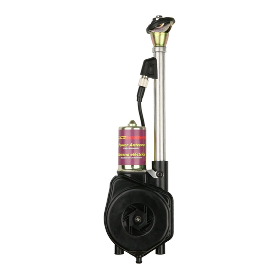
AW-PW22
Fully Automatic
AM/FM Power Antenna
Installation Instruction
REPRODUCTION OF EDITORIAL OR PICTORIAL CONTENT IS
STRICTLY PROHIBITED WITHOUT WRITTEN CONSENT OF
METRA/ROADWORKS
TM
MOUNTING WASHER
1" (25mm) HOLE
FLUSH ADJUSTABLE
3''
ANGLE BASE
GASKETS
FIG. 1
RETAINER
COAXIAL CABLE
5/8" / 16mm HOLE
ELECTRICAL
WIRES
MAST TUBE
DRAIN TUBE
METAL STRAP
This antenna is designed for optimum performance for either AM or
FM bands. The antenna is raised or lowered by operating the radio
on/off switch.
Prior to installing the antenna, read the
entire installation instructions.
May require an extension cable depending on vehicle or an anten-
na adapter cable for many 1995-up Ford, 1988-up GM and some
imports.
1.REPLACEMENT OF EXISTING POWER ANTENNA,
REMOVING OLD ANTENNA.
A) Gain access to the underside of the fender area through the
trunk, fender splash panel, etc.
B) Remove mounting bracket, drain tube, electrical wire and anten-
na coaxial cable.When removing electrical wires and coaxial cable
from the antenna, follow to the closest connector and disconnect.
DO NOT CUT COAXIAL CABLE.
MOUNTING NUT
MOUNTING SPACER
8''
15''
23''
30''
FIXED ANGLE BASES
GASKETS
7/8" / (22mm) HOLE
UNDERSIDE
OF FENDER
MOTOR
ASSEMBLY
C) Disassemble the mounting base and save the parts, they may be
used with the installation of the new antenna.
D) Remove old antenna from below fender.
E) To avoid cutting car wiring, you may want to cut the connector off
of the old antenna removed from the car, attaching the new anten-
na wiring to the old connector wires and directly plug into car wiring.
2. NEW ANTENNA INSTALLATION:
For first time antenna installations:
A) Use original factory hole or select a location on the front or back
fender of car for mounting antenna. In selecting the location, make
sure the underside of the fender is free of any obstruction such as
weld beads, braces, gussets and sub-fender.Also, be sure that suf-
ficient clearance is available under fender to house the antenna,
approximately 11-1/2" / 29cm.
B) Six mounting bases are provided with the antenna. Five fixed
angle and one adjustable angle flush mount base. (See Figure 1).
C) Remove the installed flush mounting base from new antenna.
Select the proper base with correct angle for fender (as shown in
figure 1) or reuse original mounting base previously removed from
old antenna. NOTE: The five fixed angle bases require a 7/8" /
22mm hole. The adjustable angle flush base requires a 1"
25mm hole.
D) A 1/8" / 3mm pilot hole should be drilled, then enlarged with a
hole saw or drill bit to the proper size.
E) Remove all burrs, paint, road dirt or undercoating from around the
underside of the hole.
F) Install the antenna from the underside of the fender and assem-
ble the base above the fender according to Figure 1. BE SURE THE
RETAINER RESTS EVENLY ON THE UNDERSIDE OF THE FENDER
TO ALLEVIATE ANY POSSIBLE DAMAGE TO THE VEHICLE. Align
the mast vertically by slightly tightening the antenna mounting nut
while adjusting the mast to be vertical.
G) To prevent movement and maintain the desired angle, secure the
bottom of the motor assembly with the supplied perforated strap.
Holes are provided with the strap to accommodate various mount-
ing positions. It may be necessary to bend the strap to conform to
the fit of the antenna and car. Be sure the antenna retainer is
grounded to the underside of the
fender and the black ground wire is grounded properly to the vehi-
cle chassis. If the retainer and ground wire are not properly ground-
ed, THE ANTENNA WILL NOT FUNCTION.
H) With the bottom of the antenna motor assembly secured, the
mast at the desired angle and the retainer resting evenly on the
underside of the fender, tighten the mounting nut firmly to secure
the entire antenna assembly. Do not tighten the nut excessively as
this may strip or break the mounting threads or damage contact
spring and cause improper antenna operation.
I) Attach the drain lube to the bottom of the motor assembly and
route to the outside of the car. Avoid any kinks or bends in the tube
that may restrict drainage. (as shown in figure 1.)
For new antenna installations:
J) Route electrical wiring and coaxial cable into the dash area of the
vehicle interior as shown in Figure 2. (44-PWEC157 extension
cable may be required). A 5/8" / 16mm hole may be required in the
interior panel when routing wire from front fender. If possible, avoid
routing coaxial cable into engine compartment. The electrical noise
found in this area may be transmitted into the antenna wiring.
1
Advertisement
Table of Contents

Related Manuals for Metra Electronics AW-PW22


Summary of Contents for Metra Electronics AW-PW22
-
Page 1: Installation Instruction
AW-PW22 Fully Automatic AM/FM Power Antenna Installation Instruction REPRODUCTION OF EDITORIAL OR PICTORIAL CONTENT IS STRICTLY PROHIBITED WITHOUT WRITTEN CONSENT OF METRA/ROADWORKS MOUNTING NUT MOUNTING WASHER 1“ (25mm) HOLE FLUSH ADJUSTABLE 3’’ 8’’ ANGLE BASE FIXED ANGLE BASES GASKETS GASKETS FIG. -
Page 2: Antenna Wiring
3. ANTENNA WIRING For first time antenna installations: A) Radios with switched antenna wire: Connect blue wire from antenna to the switched antenna wire from radio (normally blue) as shown in Figure 2. Connect coaxial cable from antenna to radio. B) The red power wire from antenna can be connected at fuse block. - Page 3 AW-PW22 Instructions pour I’installation d’une Antenne électrique AM/FM entièrement automatique TOUTE REPRODUCTION DE TEXTES, SCHEMAS OU GRAPHIQUES EST STRICTEMENT INTERDITE SAN L’AUTORISATION PREALABLE DE METRA/ROADWORKS ÉCROU DE MONTAGE RONDELIE DE MONTAGE BASE Å ANGLE RÉGLABLE POUR MONTAGE 3’’ 8’’ Å RAS DANS UN ORIFICE DE 1 PO/25MM BASES Å...
-
Page 4: Remarques Importantes
intérieur pour l’acheminement du fil à partir de l’aile avant. Autant que possible, éviter d’acheminer le câble coaxial dans le comparti- ment du moteur. Les bruits électroniques à cet endroit risqueraient d’être transmis au câblage de l’antenne. 3. CABLAGE DE L’ANTENNE Pour Installation initiale d’une antenne A) Radios munies d’un fil de commutation d’antenne : Brancher le fil bleu de l’antenne au fil de commutation d’antenne de... - Page 5 AW-PW22 Antena eléctrica Automática AM/FM Instrucciones para su Instalación LA REPRODUCCIO´N EDITORAL O DE LOS GRA´FICOS DE ESTE MATERIAL ESTA´N ESTRICTAMENTE PROHIBIDOS SIN EL CON- SENRIMIENTO ESCRITO DE METRA/ROADWORKS TUERCA DE MONTAJE ARANDELA MONTAJE AGUJERO EMPOTRADO 25MM (1) DE DRENAJE PARA BASE 3’’...
-
Page 6: Notas Importantes
mm (5/8”) en el panel interior al rutear el cableado desde el guard- abaros delantero. De ser posible, evite el ruteo del cable coaxial por dentro del compartimiento del motor. El ruido eléctrico que se encuentra en dicha área puede transmitirse dentro del c a b l e a d o de la antena. -
Page 7: Limited Warranty
Metra Electronics offre à l’acheteur original de ce produit une garantie contre les défauts dans les matières et la fabrication. Si ce produit devait être défectueux au cours d’une période de un an à computer de la date originale d’achat. Metra s’engage à le réparer ou a le remplacer (a la discrétion de Metra) et ce, sans frais pour les pièces. - Page 8 Metra Electronics garantiza al comprador minorista original de este producto por el termino de un ano a partir de la fecha de compra original, y siempre que se compruebe que el mismo el defectuoso, que será reparado o reemplazado (a opción de Metra) sin cargo por piezas.