
Related Manuals for Toshiba e-STUDIO203S


Summary of Contents for Toshiba e-STUDIO203S
- Page 1 SERVICE MANUAL MULTIFUNCTIONAL DIGITAL SYSTEMS e-STUDIO203S e-STUDIO203SD Model: DP-2031/2032 Publish Date: July 2008 File No. SME080002A0 R080621G0500-TTEC Ver01_2008-09...
- Page 2 © 2008 TOSHIBA TEC CORPORATION All rights reserved Under the copyright laws, this manual cannot be reproduced in any form without prior written permission of TOSHIBA TEC CORPORATION. No patent liability is assumed, however, with respect to the use of the information contained herein.
- Page 3 GENERAL PRECAUTIONS REGARDING THE INSTALLATION AND SERVICE FOR e-STUDIO203S/203SD The installation and service should be done by a qualified service technician. 1. Transportation/Installation When transporting/installing the machine, be sure to use the positions as indicated below. The machine is quite heavy and weighs approximately 16.8 kg (37 lb.), therefore pay full atten- tion when handling it.
- Page 4 Be sure to handle/install them properly. If these parts are shorted circuit and/or made their functions out, they may burn down, for instance, and may result in fatal accidents. Do not allow a short circuit to occur. Do not use the parts not recommended by Toshiba TEC Corpora- tion.
- Page 5 CAUTION This product is a class 1 laser product that complies with 21CFR 1040 of the CDRH standard and IEC60825-1. This means that this machine does not produce hazardous laser radiation. The use of controls, adjustments or performance of procedures other than those specified herein may result in hazardous radiation exposure.
- Page 6 At the production line, the output power Caution of the scanner unit is adjusted to 0.57 This product contains a low power laser MILLI-WATT PLUS 20 PCTS and is device. To ensure continued safety do not maintained constant by the operation of remove any cover or attempt to gain access the Automatic Power Control (APC).
-
Page 7: Table Of Contents
CONTENTS GENERAL E. RADF open/close detection (book document detection) ......7-8 1. Major functions ........1-1 7. - Page 8 L. Paper sensor ........8-27 M.
-
Page 9: Major Functions
SPLC E-SORT Duplex Shifter FAX DDM* RJ45 (Letter) printer 1284 Model (push) ✕ ❍ ✕ ❍ ❍ ✕ ❍ ❍ ✕ ❍ ✕ e-STUDIO203S (250) (2.0Hi) ✕ ❍ ✕ ❍ ❍ ❍ ❍ ❍ ✕ ❍ ✕ e-STUDIO203SD (250) (2.0Hi) Descriptions of items CPM:... -
Page 10: Basic Specifications
Saw-tooth charging with a grid, / (-) scorotron discharge Transfer system (+) DC corotron system Separation system (-) DC corotron system Developing Developing system Dry, 2-component magnetic brush development system Cleaning Cleaning system Counter blade system (Counter to rotation) e-STUDIO203S/203SD SPECIFICATIONS 2 - 1... -
Page 11: Copy Performance
"Selection of copy start state" set to ON in the user programs (8-1/2" x 11" (A4), paper fed from paper tray). The first-copy time may vary depending on machine operating conditions and ambient conditions such as temperature. e-STUDIO203S/203SD SPECIFICATIONS 2 - 2... -
Page 12: Splc Printer
[Conditions] Speed with tray 1, normal size, paper size of 8.5" x 11" (A4), and RADF. *1: Indicates the speed from 1st to 30th sheet (i.e., 60th surface). e-STUDIO203S/203SD SPECIFICATIONS 2 - 3... -
Page 13: Supply List
The label on the drum cartridge shows the date of production. (SOCC production) Production month –25˚C 30˚C 40˚C Production day Destination code (Dealer, distributor, OEM, etc.) Production place (SOCC: Fixed to B.) End digit of year Version No. e-STUDIO203S/203SD CONSUMABLE PARTS 3 - 1... -
Page 14: Toner Cartridge Replacement
End digit of year Production place 4. Toner cartridge replacement 1) Open the front and side cabinets of the copier. 2) Keep holding Toner lover, and 3) Carefully pull out Toner unit from the copier. e-STUDIO203S/203SD CONSUMABLE PARTS 3 - 2... -
Page 15: Appearance
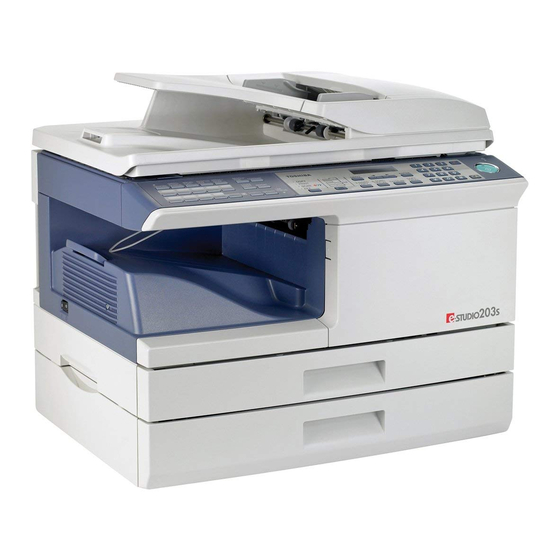
Paper output tray Paper output tray extension Power switch Handles Power cord USB connector 2. Internal Toner cartridge Drum cartridge Front cover Side cover Fusing unit release lever Transfer charger Charger cleaner e-STUDIO203S/203SD EXTERNAL VIEWS AND INTERNAL STRUCTURES 4 - 1... -
Page 16: Operation Panel
20 Shows the number of copies that has been entered with the numeric keys. 21 A checkmark " " appears when the exposure has been changed, or when two-sided copying, sort, 2 IN 1, or margin shift is selected. e-STUDIO203S/203SD EXTERNAL VIEWS AND INTERNAL STRUCTURES 4 - 2... -
Page 17: Motors, Solenoids And Clutch
Devices the duplex paper transport section (Duplex model only) 10 Shifter motor SFTM Drives the shifter. 11 Reverse clutch SRVC Reverses the rotating direction of the roller. 12 Paper feed solenoid (RADF) SPUS Feeds paper. e-STUDIO203S/203SD EXTERNAL VIEWS AND INTERNAL STRUCTURES 4 - 3... -
Page 18: Sensors And Switches
"L" at A4 size or more 10 Upper door open/close sensor SCOD Transmission sensor Cover open/close detection "L" open 11 Paper sensor SPPD Transmission sensor Paper transport detection "H" paper empty e-STUDIO203S/203SD EXTERNAL VIEWS AND INTERNAL STRUCTURES 4 - 4... -
Page 19: Pwb Unit
TCS PWB For toner sensor control LSU PWB For laser control FAX-operation PWB FAX operation input (GD-1300 option) Power PWB AC power input, DC voltage control Modem PWB FAX control (GD-1300 option) e-STUDIO203S/203SD EXTERNAL VIEWS AND INTERNAL STRUCTURES 4 - 5... -
Page 20: Cross Sectional View
17 Upper transport roller Transports of a document. 18 Paper exit roller Discharges documents. 19 Lower transport roller Transports of a document. 20 PS roller Feeds documents to the scanning section. e-STUDIO203S/203SD EXTERNAL VIEWS AND INTERNAL STRUCTURES 4 - 6... -
Page 21: Copier Installation
Also make certain the outlet is properly grounded. Drum cartridge Be sure to allow the required space around the machine for servic- (installed in unit) ing and proper ventilation. 8" (20cm) 8"(20cm) 4" 4" (10cm) (10cm) e-STUDIO203S/203SD UNPACKING AND INSTALLATION 5 - 1... -
Page 22: Unpacking
4) Remove the CAUTION tape from the front cover and remove the two protective pins from the fusing machine by pulling the strings upward one at a time. Protective pins Note: Be careful not to splash developer outside Developer CAUTION tape unit. e-STUDIO203S/203SD UNPACKING AND INSTALLATION 5 - 2... -
Page 23: Toner Cartridge Installation
Note: Do not hold and carry the shutter. Otherwise the shutter may drop and Toner unit may drop. 7) Completion of Toner unit installation Close the front and side cabinets. e-STUDIO203S/203SD UNPACKING AND INSTALLATION 5 - 3... -
Page 24: Loading The Paper Tray
OFF/ON the power SW, complete initializing of the RADF, then • The left guide is an insert-type guide. Remove it and then set the documents again. insert it at the indicator line of the paper to be loaded. e-STUDIO203S/203SD UNPACKING AND INSTALLATION 5 - 4... -
Page 25: Software
Available* Available Me/2000/XP/ Vista *1: The printer driver that is installed will vary depending on the type of connection between the machine and your computer. Install the software according to the Operation Manual. e-STUDIO203S/203SD UNPACKING AND INSTALLATION 5 - 5... - Page 26 13) Make sure that the power of the machine is turned on, and then connect the USB cable. Windows will detect the machine and a Plug and Play screen will appear. e-STUDIO203S/203SD UNPACKING AND INSTALLATION 5 - 6...
- Page 27 4) Select "Connected via the network" and click the "Next" button. 1) Insert the cable into the USB connector on the machine. 2) Insert the other end of the cable into your computer's USB port. e-STUDIO203S/203SD UNPACKING AND INSTALLATION 5 - 7...
-
Page 28: C. Setting Up Button Manager
Ask your network administrator for the server name and printer name of the machine on the network. 5) Select "Start this program" and then select "Toshiba Button Manager T" from the pull-down menu. 7) In the printer port selection window, verify the network printer that is shared and whether the machine is to be used as the default printer, make the selections and click the "Next"... -
Page 29: Interface
The pin numbers and signal names are listed in the following table. Pin No. Signal name -DATA +DATA 6) Select "Toshiba Button Manager T" in "Send to this application". 12. Moving Moving instructions When moving the unit, follow the procedure below. Note: If other applications are shown, deselect the checkboxes for... -
Page 30: Scanner Moisture-Proof Parts
(Save the screw.) much as possible. <2> Unscrew three screws and remove the rear cabinet. (Save the screws.) <3> Disconnect the connector of the RADF, and remove the RADF from the machine. e-STUDIO203S/203SD UNPACKING AND INSTALLATION 5 - 10... - Page 31 Align with the raised part (the yellow line in the diagram below). Match the center of the mylar (in the horizontal direction) to the center of the raised part. Stick the excessive part on the side. e-STUDIO203S/203SD UNPACKING AND INSTALLATION 5 - 11...
- Page 32 Press the cushion to make sure all the holes are covered. 8) Bend the edge of the Scanner motor lower mylar and stick together. Stick the lower part of the cushion to the mylar, too. Stick together. Stick together. e-STUDIO203S/203SD UNPACKING AND INSTALLATION 5 - 12...
- Page 33 Attach the cushion leaving 3 - 7mm from the edge so that the gap between the Fan housing cushion and the filter of the rear cabinet is filled for sure. 14) Attach the parts removed in the items 1), 2), and 3). e-STUDIO203S/203SD UNPACKING AND INSTALLATION 5 - 13...
-
Page 34: Functional Diagram
Waste toner box To face Synchronization Paper release Fusing Transfer Manual feed Separation down tray with drum Heat roller Electrode Transfer charger Cassette paper feed Transfer high Heater lamp voltage unit Print process Paper transport route e-STUDIO203S/203SD COPY PROCESS 6 - 1... -
Page 35: Outline Of Print Process
A uniform negative charge is applied over the OPC drum surface by layer the main charging unit. Stable potential is maintained by means of Non-image area Image area the Scorotron charger. Positive charges are generated in the aluminum layer. About DC5.5KV ( 580V/ 400V) e-STUDIO203S/203SD COPY PROCESS 6 - 2... - Page 36 It is transported to the waste toner collecting section in the cleaning unit by the waste toner transport roller. Toner is attracted over the shadowed area because of the develop- ing bias. e-STUDIO203S/203SD COPY PROCESS 6 - 3 08/09...
- Page 37 Voltage added to the screen grid can be selected, high and low. To make it easily understood, the figure below shows voltage transition at the developer unit. START STOP Print potential Toner attract Developing bias potential Drum potential High Time e-STUDIO203S/203SD COPY PROCESS 6 - 4...
-
Page 38: Outline Of Operation
5) The LSU emits laser beams according to the print data. (Electrical signals are converted into photo signals.) 6) The laser beams are radiated through the polygon mirror and various lenses to the OPC drum. e-STUDIO203S/203SD OPERATIONAL DESCRIPTIONS 7 - 1... -
Page 39: Scanner Section
473 through the idle gear, the pulley gear, the belt 190, and the idle pulley to drive the optical unit. Scanner motor Pulley gear Idle pulley Belt 473 Belt 190 Optical unit Shaft Idle gear Table glass e-STUDIO203S/203SD OPERATIONAL DESCRIPTIONS 7 - 2... -
Page 40: Laser Unit
(Refer to the figure below.) Makes the laser scanning speeds at both ends of the drum same as each other. a ≠ b ≠ c d = e = f f θ LENS e-STUDIO203S/203SD OPERATIONAL DESCRIPTIONS 7 - 3... -
Page 41: A. General Description
Level of the thermistor is controlled by the main PWB. Triac (in the power supply unit) With the signal from the main PWB, the triac is controlled on and off. (power supply PWB) e-STUDIO203S/203SD OPERATIONAL DESCRIPTIONS 7 - 4... - Page 42 (fusing section), POD (paper out latch is brought in contact with a notch on the clutch sleeve, detector) to the copy tray. stopping rotation of the pick-up roller. e-STUDIO203S/203SD OPERATIONAL DESCRIPTIONS 7 - 5...
- Page 43 (Refer to A-5 - 8.) take-up roller is pressed to the surface of the paper to start 5) The solenoid turns off to close the gate and return to the initial paper feeding. state. MPFS MPFS e-STUDIO203S/203SD OPERATIONAL DESCRIPTIONS 7 - 6...
-
Page 44: Radf Section
SPUS ON Document feed The RADF (Reversing Automatic Document Feeder) is installed to the e-STUDIO203SD / e-STUDIO203S as a standard provision, PPD ON and it automatically copies up to 50 sheets of documents of a same size. (Only one set of copies) -
Page 45: D. Cases Where A Document Jam Is Caused
• The paper is passed through the fusing section and the lower side of the gate section to the paper exit tray side. (However, it is not discharged completely.) • The paper is stopped once, and switchback operation is per- formed. (To the back copy) e-STUDIO203S/203SD OPERATIONAL DESCRIPTIONS 7 - 8... -
Page 46: Shifter
The front and the back are not in upside down. 8. Shifter Shift width: 2.5cm The offset function by the shifter is turned ON/OFF by the user pro- gram. According to the setting, offset operation is performed for every job. (Default: ON) e-STUDIO203S/203SD OPERATIONAL DESCRIPTIONS 7 - 9... -
Page 47: High Voltage Section
(When uneven charging occurs, clean the screen grid and the 1. High voltage section sawteeth with an air blower.) A. List Part name Ref. Drum Transfer charger unit Charger wire B. Drum replacement 1) Remove the drum cover. (4 Lock Tabs) e-STUDIO203S/203SD DISASSEMBLY AND ASSEMBLY 8 - 1... - Page 48 Securely set the MC holder on the projection of the process frame. Securely insert two projections of the MC holder into the groove in the process frame. When attaching the MC holder ass'y, be careful not to make contact with the cleaning blade. e-STUDIO203S/203SD DISASSEMBLY AND ASSEMBLY 8 - 2...
-
Page 49: C. Disassembly Procedure (Transfer Charger Unit)
For assembly, reverse the disassembly procedure. 1) Press the side cover open/close button and open the side E. TC unit cleaning cover. 1) Remove the charger cleaner from the manual paper feed unit. e-STUDIO203S/203SD DISASSEMBLY AND ASSEMBLY 8 - 3... -
Page 50: F. Charger Wire Replacement
Charger wire Protrusion 1.5mm Fig.1 2. Operation panel section A. List Part name Ref. Operation panel unit Operation PWB B. Disassembly procedure 1) Open the side door, and Open the front cover. e-STUDIO203S/203SD DISASSEMBLY AND ASSEMBLY 8 - 4... -
Page 51: C. Assembly Procedure
4) Disconnect the connector. 5) Remove eight screws, and remove the operation PWB. 2) Remove the connector and the clamp, and remove the RADF unit. C. Assembly procedure For assembly, reverse the disassembly procedure e-STUDIO203S/203SD DISASSEMBLY AND ASSEMBLY 8 - 5... - Page 52 8) Move the carriage to the position indicated on the figure. document from being fed. 9) Loosen the screw which is fixing the tension plate. 10) Move the tension plate in the arrow direction to release the ten- sion, and remove the belt. e-STUDIO203S/203SD DISASSEMBLY AND ASSEMBLY 8 - 6...
-
Page 53: C. Assembly Procedure
Note: Attach the FCC to Marking line. fit with the marking line. 3) Cut the binding band, remove the screw, and remove the ther- mistor. Thermistor e-STUDIO203S/203SD DISASSEMBLY AND ASSEMBLY 8 - 7... - Page 54 If the fusing unit is opened without sliding the fusing lower earth spring, the fusing lower earth spring is deformed. If the fusing lower earth spring is once deformed, the earth function may not work properly. Replace the deformed spring with a new one. e-STUDIO203S/203SD DISASSEMBLY AND ASSEMBLY 8 - 8...
- Page 55 Note: Apply grease to the sections specified with an asterisk (∗). Grease: "JFE552" 10) Remove the E-ring and remove the reverse gate. Pressure roller 11) Remove the spring, and remove the lower separation pawls (4 pcs.). e-STUDIO203S/203SD DISASSEMBLY AND ASSEMBLY 8 - 9...
-
Page 56: C. Assembly Procedure
6) Remove the C-ring and the fusing bearing, and remove the heat roller. Heat roller C. Assembly procedure For assembly, reverse the disassembly procedure. 7) Remove the parts from the heat roller. Note: Apply grease to the sections specified with ∗1. Grease: "JFE552" e-STUDIO203S/203SD DISASSEMBLY AND ASSEMBLY 8 - 10... -
Page 57: Tray Paper Feed/Transport Section
2) Remove two screws, and remove the hinge guide R. 3) Remove the fan duct and disconnect the connector. (2 posi- tions) 4) Remove six screws, and remove the scanner unit. 8) Remove the roller, and remove the belt. e-STUDIO203S/203SD DISASSEMBLY AND ASSEMBLY 8 - 11... - Page 58 16) Remove three screws, and remove the MCU PWB. 12) Remove the connector and the screw, and remove the speaker unit. (When the GD-1300 is installed) 17) Remove two screws and remove the toner motor. e-STUDIO203S/203SD DISASSEMBLY AND ASSEMBLY 8 - 12...
- Page 59 22) Remove the screw, slide the left cabinet to the left to detach it. Remove each pawl, and remove the paper exit tray. 20) Remove five screws and the grounding wire, and remove the main drive unit. CAUTION:Attach the gears securely e-STUDIO203S/203SD DISASSEMBLY AND ASSEMBLY 8 - 13...
- Page 60 Fit the lower paper guide hole (a) with the shifter gear hole (b) so that the black resin (c) of the shifter unit can be checked. 30) Put the lower paper guide unit upside down, remove two screws, and remove the shifter motor. e-STUDIO203S/203SD DISASSEMBLY AND ASSEMBLY 8 - 14...
- Page 61 PS semi-circuler PS semi-circular earth plate earth plate Note: When assembling, turn it to the right and attach. 34) Remove three screws and remove the TC front paper guide. e-STUDIO203S/203SD DISASSEMBLY AND ASSEMBLY 8 - 15...
-
Page 62: C. Assembly Procedure
36) Remove two E-rings and remove the paper feed roller. 37) Remove three E-rings and remove the clutch unit. Back C. Assembly procedure For assembly, reverse the disassembly procedure. Clutch unit Paper feed roller Front e-STUDIO203S/203SD DISASSEMBLY AND ASSEMBLY 8 - 16... -
Page 63: Manual Paper Feed Section
1) Remove the screw and remove the multi upper cover. 4) Remove two screws and remove the multi feed bracket unit from the multi paper feed upper frame. 2) Remove the screw and remove the side door detection unit. Back Wire treatment e-STUDIO203S/203SD DISASSEMBLY AND ASSEMBLY 8 - 17... -
Page 64: C. Assembly Procedure
For assembly, reverse the disassembly procedure. D. Pressure plate holder attachment 1) Attach the pressure plate holder so that the resin section is not covered with the seal M1-N. Seal M1-N Pressure plate holder Attachment reference Attachment reference e-STUDIO203S/203SD DISASSEMBLY AND ASSEMBLY 8 - 18... -
Page 65: Rear Frame Section
4) Disconnect the connector. 5) Remove two screws, and remove the scanner motor. C. Assembly procedure For assembly, reverse the disassembly procedure. 6) Remove two screws and one harness, and remove the main motor. e-STUDIO203S/203SD DISASSEMBLY AND ASSEMBLY 8 - 19... -
Page 66: Power Section
1) Peel off the old DV seal. 2) Clean the attachment surface with alcohol. 3) Attach the new DV seal to the reference position. DV side seal R DV side seal F Magnification ratio: Bump 200% X - X e-STUDIO203S/203SD DISASSEMBLY AND ASSEMBLY 8 - 20... -
Page 67: D. Dv Doctor
Note: When reassembling, be sure to engage the Duplex motor DG check gear with the belt on the main body side. position C. Assembly procedure DG check DG check DG check gauge gauge gauge For assembly, reverse the disassembly procedure. e-STUDIO203S/203SD DISASSEMBLY AND ASSEMBLY 8 - 21... -
Page 68: B. Disassembly Procedure
4) Bend the reverse roller and remove it. B. Upper door unit 1) Release the shaft on the front side. 2) Remove the upper door unit. C. Assembly procedure For assembly, reverse the disassembly procedure. e-STUDIO203S/203SD DISASSEMBLY AND ASSEMBLY 8 - 22... -
Page 69: C. Document Tray Unit
1) Disconnect one connector. 2) Remove the resin E-ring. 3) Remove the reverse clutch. ■ Note for reassembly Attach the stopper of the reverse clutch along with the rib on the motor mounting plate. e-STUDIO203S/203SD DISASSEMBLY AND ASSEMBLY 8 - 23... -
Page 70: G. Shutter Solenoid
When assembling, use care so that the paper feed solenoid spring does not extend out of the paper feed solenoid lever. ■ Note for reassembly Connect the connectors according to the arrow indication marked on the motor mounting plate. e-STUDIO203S/203SD DISASSEMBLY AND ASSEMBLY 8 - 24... -
Page 71: H. Pickup Roller, Take-Up Roller
(3) Paper feed roller removal 2) Slide and remove the paper feed PG support plate. 1) Pull out the shaft. 2) Remove the clutch boss and the clutch spring from the pickup roller. e-STUDIO203S/203SD DISASSEMBLY AND ASSEMBLY 8 - 25... -
Page 72: J. Ps Roller
Use care so that the rib on the upper transport release arm catches the guide. ■ Note for reassembly Pass the earth wire through the hole to the outside of the frame, then install parts. e-STUDIO203S/203SD DISASSEMBLY AND ASSEMBLY 8 - 26... -
Page 73: L. Paper Sensor
1) Remove the OC mat. M. Lower transport roller (1) Reverse self-weight gate removal 1) Remove the reverse self-weight gate. (2) Paper exit sensor removal 1) Disconnect one connector. 2) Remove the paper exit sensor. e-STUDIO203S/203SD DISASSEMBLY AND ASSEMBLY 8 - 27... -
Page 74: Optical Section
1) Set the scale on the document table as shown below. (Use a long scale for precise adjustment.) 2) Set the copy magnification ratio to 100%. 3) Make a copy on A4 or 81/2" x 11" paper. 4) Measure the length of the copied scale image. e-STUDIO203S/203SD ADJUSTMENTS 9 - 1... - Page 75 Image rear edge void DEN-B COPY mode lamp regarded as 0.) amount PRINT mode lamp * The RADF adjustment is made by adjusting the RADF image SCAN mode lamp scan start position after OC adjustment. e-STUDIO203S/203SD ADJUSTMENTS 9 - 2...
-
Page 76: Copy Density Adjustment
1) Arrangement before execution of the copy density adjustment • Clean the optical section. • Clean or replace the charger wire. • Check that the voltage at the high voltage section and the devel- oping bias voltage are in the specified range. e-STUDIO203S/203SD ADJUSTMENTS 9 - 3... -
Page 77: C. Necessary Tool For Copy Density Adjustment
* The value can be set in the range of 1 - 99. Test chart Test chart (2) Perform the adjustment in each mode. 1) Execute TC 46-01 (300dpi). To adjust in 600dpi, execute TC 46- e-STUDIO203S/203SD ADJUSTMENTS 9 - 4... -
Page 78: High Voltage Adjustment
(DV BIAS) and set the negative side to the frame ground (power frame). 5 10 2) Set the test chart so that the scale is positioned as shown below, in the S-D mode and the D-S mode. Scale (S-D mode) Scale (D-S mode) e-STUDIO203S/203SD ADJUSTMENTS 9 - 5... -
Page 79: B. Adjusting Trailing Edge Void In Duplex Copy Mode
(The paper information is cleared for every 2) Execute test command 50-19 to turn on the SCAN mode copy.) lamp(on the operation panel) and make the printing mode in the D-D mode. e-STUDIO203S/203SD ADJUSTMENTS 9 - 6... -
Page 80: Radf Scan Position Automatic Adjustment
Adjustment Setting Spec value Set value mode range Sub scanning At normal: 48-5 Add 1: 1 – 99 direction ±1.0% 0.1% increase magnification Reduce 1: 0.1% ratio (RADF decrease mode) 6cm or more is required. e-STUDIO203S/203SD ADJUSTMENTS 9 - 7... -
Page 81: Automatic Black Level Correction
After canceling, the machine goes into the sub code entry standby mode. THE JOB IS BEING CANCELED. 3) After execution 63-02 BLACK LEVEL *** OK 3) In case of an error 63-02 BLACK LEVEL *** ERR e-STUDIO203S/203SD ADJUSTMENTS 9 - 8... -
Page 82: Entering The Test Command Mode
Scanner mode counter clear (S-MODE CLR.) (DPLX ROT.SPEED) (e-STUDIO203SD only) Main motor operation check (MAIN MOTOR CHK) Toner motor operation (TONER MOTOR) Polygon motor operation check (LSU CHK) Cancel of trouble other than U2 (TRBL CANC.) e-STUDIO203S/203SD TEST COMMAND, TROUBLE CODES 10 - 1... - Page 83 (Executable only when the FAX is installed.) copying (RADF MAG.) Speaker sound volume setting Download mode (DOWNLOAD MODE) (Executable only when the FAX is installed.) Time setting/check (Executable only when the FAX is installed.) e-STUDIO203S/203SD TEST COMMAND, TROUBLE CODES 10 - 2...
-
Page 84: Descriptions Of Various Test Commands
[Function] (ADF MOTOR CHK) When [ENTER/START] key is pressed, the motor rotates for 10sec at the speed corresponding to the set magnification ratio. [Operation] The operation is similar to test command 1-01. e-STUDIO203S/203SD TEST COMMAND, TROUBLE CODES 10 - 3... - Page 85 ■■■■■■■■■■■■■■■■■■■■■ ■■■■■■■■■■■■■■■■■■■■■ 2) When [MODE SWITCH] key is pressed, the machine goes into the individual ON mode. <Key input check mode> 1) Initial display 2) [ENTER/START] 05-01 LCD/LED CHK. 05-01 LCD/LED CHK. e-STUDIO203S/203SD TEST COMMAND, TROUBLE CODES 10 - 4...
- Page 86 (interval 0sec). To cancel the test command, turn off the power or execute a test command which causes hard- ware reset. [Operation] 1) Initial display 2) After 10sec 07-01 W-UP/AGING 07-01 W-UP/AGING e-STUDIO203S/203SD TEST COMMAND, TROUBLE CODES 10 - 5...
- Page 87 When [ENTER/START] key is pressed, the transfer charger is outputted for 30sec. After completion of this process, the machine goes into the sub code entry standby mode. [Operation] 1) Initial display 08-03 THV SET. EXECUTING... e-STUDIO203S/203SD TEST COMMAND, TROUBLE CODES 10 - 6...
- Page 88 16-00 U2 TRBL CANC. CLEARED Maintenance counter clear [Function] (M-CNT CLR.) When [ENTER/START] key is pressed, the maintenance count value is cleared and "000,000" is displayed. [Operation] 1) Initial display 20-01 M-CNT CLR. CLEARED 000,000 e-STUDIO203S/203SD TEST COMMAND, TROUBLE CODES 10 - 7...
- Page 89 The developer counter data is acquired and displayed on the LCD. [Operation] 1) Initial display 22-06 DVLP CNT ***,*** RADF counter display [Function] (ADF CNT) The RADF counter is displayed. [Operation] 1) Initial display 22-08 ADF CNT ***,*** e-STUDIO203S/203SD TEST COMMAND, TROUBLE CODES 10 - 8...
- Page 90 00.00 ← 2) [ /10KEY] 22-14 ROM VER. LCD DATA 00.00 Duplex counter display [Function] (DPLX CNT) The duplex counter is displayed. (e-STUDIO203SD only) [Operation] 1) Initial display 22-16 DPLX CNT ***,*** e-STUDIO203S/203SD TEST COMMAND, TROUBLE CODES 10 - 9...
- Page 91 (DPLX CLR.) When [ENTER/START] key is pressed, the duplex counter value is cleared to 0, and "000,000" (e-STUDIO203SD only) is displayed on the LCD. [Operation] 1) Initial display 24-05 DPLX CLR. CLEARED 000,000 e-STUDIO203S/203SD TEST COMMAND, TROUBLE CODES 10 - 10...
- Page 92 (S-MODE CLR.) When [ENTER/START] key is pressed, the scanner mode counter value is cleared to 0, and "000,000" is displayed on the LCD. [Operation] 1) Initial display 24-15 S-MODE CLR. CLEARED 000,000 e-STUDIO203S/203SD TEST COMMAND, TROUBLE CODES 10 - 11...
- Page 93 [ENTER/START] key to save the setting. Code number Duplex Display item Duplex NO Duplex YES* * e-STUDIO203S: cannot be executed. [Operation] The operation is similar to test command 21-01. e-STUDIO203S/203SD TEST COMMAND, TROUBLE CODES 10 - 12...
- Page 94 Japan AB series – China (EX Japan AB series + China paper support) CHINA ∗ Code numbers 2 and 3 cannot be selected for the e-STUDIO203S and the e-STUDIO203SD. [Operation] The operation is similar to test command 21-01. Machine conditions check [Function] (CPM) When this test command is executed, the current machine setting is displayed.
- Page 95 11( 0-21 ) 4) [ENTER/START] Settles entered ← → 2) [ ] Mode selection value. The display is shifted to the sub code input standby menu. 26-42 TC ON TIMING F-END 50( 1-99 ) e-STUDIO203S/203SD TEST COMMAND, TROUBLE CODES 10 - 14...
- Page 96 Since the manual paper feed sensor is a single bypass sensor, its status is not displayed. ∗ The width sensor is available only in the FAX models. [Operation] 1) Initial display 2) When sensor ON 30-01 P-SENSOR 30-01 POD PPD1 PPD2 PPD3 e-STUDIO203S/203SD TEST COMMAND, TROUBLE CODES 10 - 15...
- Page 97 6( 0-8 ) 4) [ENTER/START] Settles entered ← → 2) [ ] Mode selection value. The display is shifted to the sub code input standby menu. 43-01 FU TEMP 6( 0-8 ) e-STUDIO203S/203SD TEST COMMAND, TROUBLE CODES 10 - 16...
- Page 98 /10KEY] to switch the setting, and press [ENTER/START] key to save it to the EEPROM. The machine goes to the sub code entry standby mode. Code Set temperature (°C) Remark Default [Operation] The operation is similar to test command 43-01. e-STUDIO203S/203SD TEST COMMAND, TROUBLE CODES 10 - 17...
- Page 99 SCAN mode lamp TS mode (TEXT) (600dpi) TSTXT PRINT mode lamp SCAN mode lamp TS mode (AE) (600dpi) TSAE COPY mode lamp SCAN mode lamp [Operation] The operation is similar to test command 46-01. e-STUDIO203S/203SD TEST COMMAND, TROUBLE CODES 10 - 18...
- Page 100 FAX side.) PRINT 2) Enter a 2-digit value as the exposure After completion of printing, returns to “2)” adjustment value with [10KEY]. display. ADJUST EXP. FINE ("YY" is the entered exposure adjustment value.) e-STUDIO203S/203SD TEST COMMAND, TROUBLE CODES 10 - 19...
- Page 101 PRINT mode lamp SCAN mode lamp TS mode (AE) (300dpi) TSAE COPY mode lamp SCAN mode lamp ∗ No density display on LCD. [Operation] The operation is similar to test command 46-01. e-STUDIO203S/203SD TEST COMMAND, TROUBLE CODES 10 - 20...
- Page 102 When the set value is increased, copy becomes darker. When the set value is decreased, copy becomes lighter. (Adjustment range: 1 – 99) Mode Display item Default Remark RADF [Operation] The operation is similar to test command 46-01. e-STUDIO203S/203SD TEST COMMAND, TROUBLE CODES 10 - 21...
- Page 103 SCAN mode lamp TS mode (TEXT) TSTXT PRINT mode lamp SCAN mode lamp TS mode (AE) TSAE COPY mode lamp SCAN mode lamp [Operation] The operation is similar to test command 46-01. e-STUDIO203S/203SD TEST COMMAND, TROUBLE CODES 10 - 22...
- Page 104 ("ZZZZ" is the mode selected among STD, FINE, S-FINE, FINE/PHOTO, and S-FINE/ PHOTO.) ("X" is the corresponding sharpness adjust- ment value of the selected mode stored on the FAX side.) ∗ [CLEAR] key: Returns to “2)” display. e-STUDIO203S/203SD TEST COMMAND, TROUBLE CODES 10 - 23...
- Page 105 Sub scan magnification ratio adjustment SIDE2 PRINT on the back surface of RADF document mode lamp ∗ When there is no document in RADF, copy is inhibited. [Operation] The operation is similar to test command 46-01. e-STUDIO203S/203SD TEST COMMAND, TROUBLE CODES 10 - 24...
- Page 106 To enter the download mode, there is a method to use key operations as well as to use a test ← command. With the power OFF, press and hold [CA] + [ ], turn on the power. [Operation] 1) Initial display DOWNLOAD MODE e-STUDIO203S/203SD TEST COMMAND, TROUBLE CODES 10 - 25...
- Page 107 The RSFP adjustment is made by adjusting the RADF image scan start position after OC adjustment. (Example) Distance from the paper lead edge to the image lead edge, H = 5mm Image loss, R = 4mm 10mm [Operation] The operation is similar to test command 46-01. e-STUDIO203S/203SD TEST COMMAND, TROUBLE CODES 10 - 26...
- Page 108 ADF document front scan PRINT mode lamp RADF document back scan RADF SCAN mode lamp ∗ When paper is discharged, the shifter is operated. [Operation] The operation is similar to test command 46-01. e-STUDIO203S/203SD TEST COMMAND, TROUBLE CODES 10 - 27...
- Page 109 The initial value for duplex setting is "1to2/Short Edge" for the OC setting, or "2to2" for the RADF setting. ∗ When paper is discharged, the shifter is operated. [Operation] The operation is similar to test command 46-01. e-STUDIO203S/203SD TEST COMMAND, TROUBLE CODES 10 - 28...
- Page 110 When [ENTER/START] key is pressed, HSYNC is performed and the polygon motor is rotated for 30sec. At that time, the COPY mode lamp is lighted for 100msec every time when HSYNC is detected. [Operation] 1) Initial display 61-03 LSU CHK EXECUTING... e-STUDIO203S/203SD TEST COMMAND, TROUBLE CODES 10 - 29...
- Page 111 Setting range: 0 – 99 (Complying with the light quantity stable wait time of 0 – 99sec.) Default: 15 (15sec) [Operation] The operation is similar to test command 9-04. e-STUDIO203S/203SD TEST COMMAND, TROUBLE CODES 10 - 30...
- Page 112 FAX soft SW initializing [Function] (excluding the adjustment Use to initializing FAX soft SW. values) (Executable only [Operation] when the FAX is installed.) 1) Initial display INITIALIZED After 2sec, FAX control is terminated. e-STUDIO203S/203SD TEST COMMAND, TROUBLE CODES 10 - 31...
- Page 113 1:NO SIGNAL 35:LINE ON HOOK ∗ [CLEAR] key: FAX control is terminated. 3) [ENTER] key Send after setting OUTPUTING SIGNAL MAX PRESS CLEAR TO STOP ∗ [CLEAR] key: Returns to "1) Initial display". e-STUDIO203S/203SD TEST COMMAND, TROUBLE CODES 10 - 32...
- Page 114 After completion of memory clear, the buzzer After completion of memory clear sounds. CLEARED CLEARED PLEASE POWER OFF After 2sec, FAX control is terminated. Remains unchanged until the power is turned off. e-STUDIO203S/203SD TEST COMMAND, TROUBLE CODES 10 - 33...
- Page 115 ..SELECT SIGNAL (1-6) 1:NO SIGNAL 6:00001 ∗ [CLEAR] key: FAX control is terminated. 3) [ENTER] key OUTPUTING SIGNAL SSW PRESS CLEAR TO STOP ∗ [CLEAR] key: Returns to "1) Initial display". e-STUDIO203S/203SD TEST COMMAND, TROUBLE CODES 10 - 34...
- Page 116 PRESS CLEAR TO STOP ∗ [CLEAR] key: FAX control is terminated. ∗ [CLEAR] key: Returns to "1) Initial display". 2) [10KEY] input The content selected with signal send level selection is set inside. e-STUDIO203S/203SD TEST COMMAND, TROUBLE CODES 10 - 35...
- Page 117 FAX is installed.) [Operation] 1) Initial display HS2 :xxx HS1 :xxx RHS :xxx EXHS:xxx ↑ The display is switched every 2sec. ↓ CHECKING PRESS CLEAR TO STOP ∗ [CLEAR] key: FAX control is terminated. e-STUDIO203S/203SD TEST COMMAND, TROUBLE CODES 10 - 36...
- Page 118 When [←] key is pressed, the sequence is reversed. SELECT (1-4) SELECT (1-4) ..1:NO SOUND 2:LOW ∗ [CLEAR] key: FAX control is terminated. 3) [ENTER] key STORED xxx: Set content After 2sec, FAX control is terminated. e-STUDIO203S/203SD TEST COMMAND, TROUBLE CODES 10 - 37...
- Page 119 "xxxx.xx.xx(xxx) is the entered value. STORED ∗ Select 2: Returns to "1) Initial display". 7) Select 1 After 2sec, returns to "1) Initial display". STORED After 2sec, returns to "1) Initial display". e-STUDIO203S/203SD TEST COMMAND, TROUBLE CODES 10 - 38...
-
Page 120: Trouble Codes
CRUM chip trouble normally. Improper developing unit Check that the laser emitting diode Check Replace the CRUM chip. generates laser beams. Replace the developing unit. Replace the LSU unit. remedy Replace the MCU PWB. e-STUDIO203S/203SD TEST COMMAND, TROUBLE CODES 10 - 39... - Page 121 Check the harness and the connector between the mirror motor and the MCU PWB. Replace the mirror unit. Replace the MCU PWB. When the mirror does feed. Use TC 1-02 to check the mirror home position sensor. e-STUDIO203S/203SD TEST COMMAND, TROUBLE CODES 10 - 40...
- Page 122 (stable state). Cause Exhaust fan motor connector connection trouble Exhaust fan motor trouble MCU PWB trouble Check Exhaust fan motor connector connection check remedy Exhaust fan motor replacement Replace the MCU PWB. e-STUDIO203S/203SD TEST COMMAND, TROUBLE CODES 10 - 41...
-
Page 123: Maintenance Table
Selection is available among 25K, 13K, 9K, 6K, 3K, and free (no lighting) with SIM 21-1. ∗ Default: 25K ∗ Clear: SIM 20-1 Machine Not stop. Note: When developer is replaced, be sure to execute simulation No. 24-06 to reset the counter. e-STUDIO203S/203SD MAINTENANCE 11 - 1 08/09... -
Page 124: User Programs
• Use this setting to select how long a key must be pressed for the input to be 2: 0.5 SEC. accepted. By selecting a longer time, you can prevent settings from being 3: 1.0 SEC. changed by the accidental pressing of a key. 4: 1.5 SEC. 5: 2.0 SEC. e-STUDIO203S/203SD USER PROGRAM 12 - 1... -
Page 125: B. Print Mode
The function can be disabled. : The scanning speed increases when the USB 2.0 mode is set to "HI-SPEED", however, the printing speed does not increase considerably. : When the 250-sheet paper feed unit is installed. e-STUDIO203S/203SD USER PROGRAM 12 - 2... -
Page 126: Selecting A Setting For A User Program
Your selection appears briefly and then the previous screen appears. NOTE: When "AE LEVEL ADJUST" is selected in the user programs and the [ENTER] key is pressed, the automatic exposure adjustment screen appears. Adjust the exposure and press the [ENTER] key. e-STUDIO203S/203SD USER PROGRAM 12 - 3... -
Page 127: Block Diagram
[13] ELECTRICAL SECTION 1. Block diagram A. Overall block diagram e-STUDIO203S/203SD ELECTRICAL SECTION 13 - 1... -
Page 128: Signal Name List
Key scan output Key scan output Operation section KEYSC3 Key scan output Key scan output Operation section LCDCON LCD control signal Signal for LCD Operation section LCDDB4 LCD data signal Signal for LCD Operation section e-STUDIO203S/203SD ELECTRICAL SECTION 13 - 2... - Page 129 2nd CS paper transport detection 2nd cassette section Power save LED Operation section Start button control Operation section RTH_IN Thermistor Fusing section thermistor temperature detection Fusing section SCOD SCOD sensor RADF cover open sensor RADF section e-STUDIO203S/203SD ELECTRICAL SECTION 13 - 3...
- Page 130 Toner motor phase control Toner motor drive section USB +D USB signal USB section USB -D USB signal USB section Copy lamp Copy lamp control Scanner unit section VFMOUT Fusing fan Fan drive signal Optical section e-STUDIO203S/203SD ELECTRICAL SECTION 13 - 4...
- Page 131 [14] CIRCUIT DIAGRAM 1. MCU PWB e-STUDIO203S/203SD CIRCUIT DIAGRAM 14 - 1...
- Page 132 CIRCUIT DIAGRAM 14 - 2...
- Page 133 CIRCUIT DIAGRAM 14 - 3...
- Page 134 CIRCUIT DIAGRAM 14 - 4...
- Page 135 CIRCUIT DIAGRAM 14 - 5...
- Page 136 CIRCUIT DIAGRAM 14 - 6...
- Page 137 CIRCUIT DIAGRAM 14 - 7...
- Page 138 CIRCUIT DIAGRAM 14 - 8...
- Page 139 CIRCUIT DIAGRAM 14 - 9...
- Page 140 CIRCUIT DIAGRAM 14 - 10...
- Page 141 CIRCUIT DIAGRAM 14 - 11...
- Page 142 CIRCUIT DIAGRAM 14 - 12...
- Page 143 CIRCUIT DIAGRAM 14 - 13...
- Page 144 CIRCUIT DIAGRAM 14 - 14...
- Page 145 CIRCUIT DIAGRAM 14 - 15...
- Page 146 CIRCUIT DIAGRAM 14 - 16...
-
Page 147: Operation Pwb
2. OPERATION PWB e-STUDIO203S/203SD CIRCUIT DIAGRAM 14 - 17... - Page 148 CIRCUIT DIAGRAM 14 - 18...
- Page 149 CIRCUIT DIAGRAM 14 - 19...
-
Page 150: Actual Wiring Diagram
3. ACTUAL WIRING DIAGRAM (1) MCU section (1/3) e-STUDIO203S/203SD CIRCUIT DIAGRAM 14 - 20... - Page 151 (2) RADF section (2/3) e-STUDIO203S/203SD CIRCUIT DIAGRAM 14 - 21...
- Page 152 (3) 2nd cassette section (Optional) e-STUDIO203S/203SD CIRCUIT DIAGRAM 14 - 22...
- Page 153 (4) Network box and FAX section (Optional) e-STUDIO203S/203SD CIRCUIT DIAGRAM 14 - 23...
-
Page 154: Download Procedures
2) Connect machine and the PC with a USB cable. (Connect it to the USB port on the main unit without fail. 3) PC side: Boost "Maintenance.exe" and select "e-STUDIO202/ 203 series Module" in the Select Model menu. e-STUDIO203S/203SD FIRMWARE DOWNLOAD PROCEDURES 15 - 1... - Page 155 COMPLETE!" is displayed, download is completed. Turn OFF the power of the machine, and disconnect the USB cable. 12) Terminate the integration maintenance program, and turn ON the machine again. Download is completed with the above procedures. e-STUDIO203S/203SD FIRMWARE DOWNLOAD PROCEDURES 15 - 2...
-
Page 156: Version Acquisition Procedures
DOWN] key (left key) together, and turn on the power simulta- neously.) 2) Connect the machine and the PC with a USB cable. 3) PC side: Boost "Maintenance.exe" and select "e-STUDIO202/ 203 series Module" in the "Select Model" menu. e-STUDIO203S/203SD FIRMWARE DOWNLOAD PROCEDURES 15 - 3... -
Page 157: Eeprom Data Acquisition Procedure
DOWN] key (left key) together, and turn on the power simulta- neously.) 2) Connect the machine and the PC with a USB cable. 3) PC side: Boot "Maintenance.exe" and select "e-STUDIO202/ 203 series Module" in the "Select Model" menu. e-STUDIO203S/203SD FIRMWARE DOWNLOAD PROCEDURES 15 - 4... -
Page 158: Installing Procedures
9) PC side: When upload is completed, the complete message is displayed. With the above procedure, the EEPROM data acquisition is com- pleted. Data acquired by the EEPROM data acquisition procedure are saved in a file with extension of .eep. e-STUDIO203S/203SD FIRMWARE DOWNLOAD PROCEDURES 15 - 5... - Page 159 10) When the following display is shown, close [Close] button to complete installation. 7) Press [Browse] button, specify the folder which includes the maintenance tool driver (Maintenance.inf), and press [OK] but- ton. e-STUDIO203S/203SD FIRMWARE DOWNLOAD PROCEDURES 15 - 6...
- Page 160 (Mainte.inf), select <Browse>. If the search location is the folder which includes the maintenance tool driver, press <Next> but- ton to go to procedure 7). 7) When the following display is shown, press [Continue Anyway] button. e-STUDIO203S/203SD FIRMWARE DOWNLOAD PROCEDURES 15 - 7...
- Page 161 3) Check that the Found New Hardware Wizard is displayed, and press <Next> button. 7) Specify the folder which includes the maintenance tool driver (Mainte.inf), and press <Open> button. 4) Select [Search for a suitable driver for my device] and press <Next> button. e-STUDIO203S/203SD FIRMWARE DOWNLOAD PROCEDURES 15 - 8...
- Page 162 C:\MaintenanceTool\Drivers\Win9xMe folder.) 10) When the following display is shown, installation is completed. Press <Finish> button. 11) Restart the PC. With the above procedures, installation (on Windows 2000) of the integration maintenance program is completed. e-STUDIO203S/203SD FIRMWARE DOWNLOAD PROCEDURES 15 - 9...
- Page 163 7) When the following display is shown, installation is completed. Press <Finish> button. 8) Restart the PC. With the above procedures, installation (on Windows ME) of the integration maintenance program is completed. e-STUDIO203S/203SD FIRMWARE DOWNLOAD PROCEDURES 15 - 10...
- Page 164 LEAD-FREE SOLDER The PWB’s of this model employs lead-free solder. The “LF” marks indicated on the PWB’s and the Service Manual mean “Lead-Free” solder. The alphabet following the LF mark shows the kind of lead-free solder. Example: <Solder composition code of lead-free solder> Solder composition Solder composition code Solder composition...
- Page 165 CAUTION FOR BATTERY REPLACEMENT (Danish) ADVARSEL ! Lithiumbatteri – Eksplosionsfare ved fejlagtig håndtering. Udskiftning må kun ske med batteri af samme fabrikat og type. Levér det brugte batteri tilbage til leverandoren. (English) Caution ! Danger of explosion if battery is incorrectly replaced. Replace only with the same or equivalent type recommended by the manufacturer.