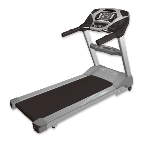
Spirit xt685 Owner's Manual
Hide thumbs
Also See for xt685:
- Owner's manual (48 pages) ,
- Owner's manual (39 pages) ,
- Owner's manual (39 pages)

Related Manuals for Spirit xt685


Summary of Contents for Spirit xt685
- Page 1 OWNER’S MANUAL Please carefully read this entire manual before operating your new treadmill...
-
Page 2: Table Of Contents
TABLE OF CONTENTS Important Safety Instructions Important Electrical Instructions Grounding Instructions Important Operation Instructions Assembly Instructions Transport Instructions Features Console Operation Programmable Features Using Heart Rate Transmitter General Maintenance Exploded View Diagram/Parts List ATTENTION This treadmill is intended for residential use only and is warranted for this application. Any other application voids this warranty in its entirety. -
Page 3: Important Safety Instructions
IMPORTANT SAFETY INSTRUCTIONS WARNING - Read all instructions before using this appliance. DANGER - To reduce the risk of electric shock disconnect your treadmill from the electrical outlet prior to cleaning and/or service work. WARNING - To reduce the risk of burns, fire, electric shock, or injury to persons, install the treadmill on a flat level surface with access to a 230-volt, 10-amp grounded outlet with only the treadmill plugged into the circuit. -
Page 4: Important Electrical Instructions
IMPORTANT ELECTRICAL INSTRUCTIONS WARNING! NEVER use a ground fault circuit interrupt (GFCI) wall outlet with this treadmill. As with any appliance with a large motor, the GFCI will trip often. Route the power cord away from any moving part of the treadmill including the elevation mechanism and transport wheels. -
Page 5: Important Operation Instructions
IMPORTANT OPERATION INSTRUCTIONS NEVER operate this treadmill without reading and completely understanding the results of any operational change you request from the computer. Understand that changes in speed and incline do not occur immediately. Set your desired work level on the computer console and release the adjustment key. The computer will obey the command gradually. -
Page 6: Assembly Instructions
ASSEMBLY INSTRUCTIONS !!ATTENTION: IMPORTANT UNPACKING INSTRUCTIONS. PLEASE READ BEFORE UNPACKING YOUR FOLDING TREADMILL!! Serious injury could occur if this folding treadmill is not unpacked properly. There is a Velcro strap installed around the treadmill base that prevents the treadmill from unfolding accidentally during shipping. If this strap is not removed properly the treadmill could spring open unexpectedly and cause injury if someone is standing near the treadmill when the strap is removed. -
Page 7: Upright Tube Assembly
UPRIGHT TUBE ASSEMBLY 1. Slide the bottom console covers onto the console mast tubes (52 onto 5 Left side & 53 onto 4 Right side). Make sure they are oriented as shown in the illustration. 2. Connect computer cables (32 & 33) on the right side. 3. -
Page 9: Console Assembly
CONSOLE ASSEMBLY 1. Connect the following cables together: Incline cables 35 to 39, Speed cables 34 to 38, and Computer cables 33 to 31. 2. Place the console (37) onto the brackets at the top of the console mast tubes and attach with two Button Head Bolts (104) and two Split Washers (108) on each side. - Page 10 BASE COVERS 1. Attach the bottom console covers (52 & 53) to the console with five Sheet Metal Screws (105) on each side. Tighten with the Phillips Head Screw Driver (109) or Combination M5 Allen Wrench & Phillips Head Screw Driver (107). 2.
- Page 11 PLASTIC PARTS ASSEMBLY Place two M5 Speed Nut Clips (84) onto each side of the frame. 2. Attach the side covers (40 & 41) to the frame with one Self Tapping Screw (146) and three Self Tapping Screws (147) on each side. Refer to the illustration for screw placement. Tighten with the Phillips Head Screw Driver (109).
-
Page 12: Transport Instructions
TRANSPORTATION INSTRUCTIONS Carefully lift the treadmill at the rear roller area, grasping the two end caps, and roll the treadmill away. -
Page 13: Features
FEATURES HANDRAIL ADJUSTMENTS The treadmill allows you to make speed and incline changes on the side handrails. You can also choose to turn these off if you frequently hold on to these rails. This is achieved by pressing the disable button on the right side of the lower portion of the console. - Page 14 The console will display Pace, Calories burned, Time (elapsed or countdown), Distance travelled, Pulse, Speed, Incline, Program Name, # of Laps completed, and Segment Time. There is also a Speed & Incline profile graph that lets you see how hard you have worked and how challenging the upcoming segments will be.
-
Page 15: Console Operation
OPERATION OF YOUR CONSOLE GETTING FAMILIAR WITH THE CONTROL PANEL CONSOLE GETTING STARTED Power the treadmill on by plugging it into an appropriate wall outlet, then turn on the power switch located at the front of the treadmill below the motor cover. Ensure that the safety key is installed, as the treadmill will not power on without it. -
Page 16: Incline Feature
QUICK-START/MANUAL OPERATION STEP 1: Press and release the Start key to wake display up (if not already on). Note: Installing the tether key will also wake up the console. STEP 2: Press and release the Start key to begin belt movement, at .5 mph (1 kmph), then adjust to the desired speed using the + / –... -
Page 17: Pulse Grip Feature
1/4 MILE (0.4 KM) TRACK The 1/4-mile or 0.4 km track (one lap) will be displayed around the dot matrix window. The flashing segment indicates your progress. Once the 1/4-mile (Metric - 0.4k) is complete this feature will begin again. There is a lap counter in the message window for monitoring your distance. -
Page 18: Programmable Features
PROGRAMMABLE FEATURES The treadmill offers nine factory preset-programs, two user defined programs and one Manual program. Each preset program has a maximum speed level that is displayed when a desired workout is chosen. The maximum speed that the particular program will achieve will be displayed in the Speed window. -
Page 19: User Programs
USER PROGRAMS STEP 1: Press the User 1-2 key once for User 1 or twice for User 2 then press Enter. Note that the dot matrix display portion will have a single row of segments at the bottom (Unless there is a previously stored program). STEP 2: The Message Center will now be blinking an Age value. - Page 20 FUSION PROGRAM STEP 1: Press the Fusion key. Press Enter to select the program. The display will prompt you through the programming. STEP 2: If Enter was pressed, the Message Center will now be blinking a value, indicating your Age (default is 35).
- Page 21 DUMBBELL BENT OVER ROW EMPHASIS: MID/UPPER BACK & FRONT OF ARMS 1. Grasp the dumbbells with an overhand grip and arms fully extended in front of thighs; feet are spaced shoulder width apart 2. Maintain a slightly arched lower back throughout the exercise (see side view) 3.
- Page 22 DUMBBELL SHOULDER PRESS EMPHASIS: SHOULDERS 1. Hold the dumbbells at shoulder height with an overhand (palms facing forward) or neutral (palms facing one another) grip 2. Press the dumbbells straight overhead until your arms are fully extended 3. Slowly lower to the start position 4.
-
Page 23: Preset Programs
PRESET PROGRAMS The treadmill has eight different programs that have been designed for a variety of workouts. Seven of these programs have factory preset Speed and Incline level profiles for achieving different goals. Hill Resistance: This program follows a triangle or pyramid type of gradual progression from approximately 10% of maximum effort (the level that you chose before starting this program) up to a maximum effort which lasts for 10% of the total workout time, then a gradual regression of resistance back to approximately 10% of maximum effort. - Page 24 Strength Resistance: This program has a gradual progression of speed up to 100% of maximum effort that is sustained for 25% of workout duration. This will help build strength and muscular endurance in the lower body and gluts. A brief cool down follows.
-
Page 25: Heart Rate Programs
HEART RATE PROGRAMS The old motto, “no pain, no gain”, is a myth that has been overpowered by the benefits of exercising comfortably. A great deal of this success has been promoted by the use of heart rate monitors. With the proper use of a heart rate monitor, many people find that their usual choice of exercise intensity was either too high or too low and exercise is much more enjoyable by maintaining their heart rate in the desired benefit range. - Page 26 RATE OF PERCEIVED EXERTION Heart rate is important but listening to your body also has a lot of advantages. There are more variables involved in how hard you should workout than just heart rate. Your stress level, physical health, emotional health, temperature, humidity, the time of day, the last time you ate and what you ate, all contribute to the intensity at which you should workout.
-
Page 27: Using Heart Rate Transmitter
USING HEART RATE TRANSMITTER (OPTIONAL) How to wear your wireless chest strap transmitter: 1. Attach the transmitter to the elastic strap using the locking parts. 2. Adjust the strap as tightly as possible as long as the strap is not too tight to remain comfortable. -
Page 28: Heart Rate Program Operation
HEART RATE PROGRAM OPERATION Note: You must wear the heart rate transmitter strap for these programs Both programs operate the same, the only difference is that HR1 is set to 60% and HR2 is set to 80% of the maximum heart rate. They both are programmed the same way. To start a HR program follow the instructions below or just select the HR1 or HR2 program, then the Enter button and follow the directions in the Message Center. -
Page 29: General Maintenance
GENERAL MAINTENANCE BELT/DECK Your treadmill uses a very high-efficient low-friction deck. Performance is maximized when the deck is kept as clean as possible. Use a soft, damp cloth, or paper towel, wipe the edge of the belt and the area between the belt edge and the frame. Also reach as far as practical directly under the belt edge. -
Page 30: Treadbelt Tracking Adjustment
TREADBELT TRACKING ADJUSTMENT The treadmill is designed so that the tread-belt remains reasonably centered while in use. It is normal for some belts to drift near one side while in use, depending on a user’s gait and if they favor one leg. But if during use the belt continues to move toward one side, adjustments are necessary. - Page 31 BELT/DECK LUBRICATION PROCEDURE Do not lubricate with other than approved lubricant. Your treadmill comes with one tube of lubricant and extra tubes can be ordered directly from your authorized dealer. There are commercially available lube kits, but the only one currently approved is Lube-N-Walk.
- Page 32 SERVICE CHECKLIST - DIAGNOSIS GUIDE Before contacting your dealer for aid, please review the following information. It may save you both time and expense. This list includes common problems that may not be covered under the treadmill’s warranty. PROBLEM SOLUTION/CAUSE Display does not light 1.
-
Page 33: Calibration Procedure
CALIBRATION PROCEDURE 1. Remove the safety key 2. Press and hold down the Start and Fast + buttons and replace the safety key. Continue to hold the Start and Fast key until the window displays “Factory settings”, then press the Enter key. 3. -
Page 34: Exploded View Diagram/Parts List
EXPLODED VIEW DIAGRAM... -
Page 35: Parts List
PARTS LIST Dwg # Part description Main Frame Incline Bracket Handrail Support Right Upright Left Upright Console Support Deck Cross Brace Front Roller W/Pulley Rear Roller Running Deck Running Belt PVC Handgrip Wire Tie Mount Lubricant Frame Cover Drive Motor Incline Motor Controller 1000m/m_Sensor W/Cable... - Page 36 Dwg # Part description 37~17 Front Console Cover (Bottom) 37~18 400m/m_Safety Switch Module W/Cable 37~19 Fan Assembly 37~20 Deflector Fan Grill 37~21 Fan Grill Anchor 37~22 350m/m_Speaker W/Cable (Optional) 37~24 Amplifier Controller (Optional) 37~25 Receiver, HR Assembly (Optional) 37~26 Amplifier Cable (Optional) 37~27 400m/m_Console Ground Wire 37~28 Water-resist Rubber...
- Page 37 Dwg # Part description 3/8" × 1-3/4"_Hex Head Bolt M8 × 60m/m_Hex Head Bolt M8 × 80m/m_Socket Head Cap Bolt M8 × 55m/m_Flat Head Countersink Bolt M8 × 35m/m_Flat Head Countersink Bolt 3/8" × 3/4"_Button Head Socket Bolt 3/8" × 1-1/4"_Hex Head Bolt 1/2"...
- Page 38 Dwg # Part description 400m/m_Audio Cable (Optional) 3.5 × 55m/m_Sheet Metal Screw Safety Key Sleeve Drink Bottle (Optional) Chest Strap (Optional) M5 × 10m/m_Phillips Head Screw M5 × 1.5T_Split Washer 5 × 16m/m_Tapping Screw 5 × 16m/m_Tapping Screw 300m/m_Ground Wire Choke Filter 600m/m_Connecting Cable Of Motor...