Table of Contents
Advertisement
Advertisement
Table of Contents

Related Manuals for MSI MS-7520 ECLIPSE Series


Summary of Contents for MSI MS-7520 ECLIPSE Series
- Page 1 ECLIPSE Series MS-7520 (v1.X) Mainboard...
-
Page 2: Trademarks
Alternatively, please try the following help resources for further guidance. Visit the MSI website for FAQ, technical guide, BIOS updates, driver updates, an d ot h er i n f orm at i on: h t t p: / / g l o ba l . -
Page 3: Safety Instructions
Safety Instructions Always read the safety instructions carefully. Keep this User’s Manual for future reference. Keep this equipment away from humidity. Lay this equipment on a reliable flat surface before setting it up. The openings on the enclosure are for air convection hence protects the equip- ment from overheating. -
Page 4: Fcc-B Radio Frequency Interference Statement
FCC-B Radio Frequency Interference Statement This equipment has been tested and found to comply with the limits for a Class B digital device, purs uant to Part 15 of the FCC Rules. These limits are designed to provide reasonable protection against harmful interference in a residential installation. -
Page 5: Weee (Waste Electrical And Electronic Equipment) Statement
WEEE (Waste Electrical and Electronic Equipment) Statement... -
Page 8: Table Of Contents
CONTENTS Copyright Notice ......................ii Trademarks ........................ii Revision History ......................ii Technical Support ......................ii Safety Instructions ......................iii FCC-B Radio Frequency Interference Statement ............iv W EEE (Waste Electrical and Electronic Equipment) Statement ........v Chapter 1. Getting Started ..................1-1 Mainboard Specifications ................... - Page 9 Appendix A X-Fi Xtreme Audio Card ..............A-1 Introduction ......................A-2 Hardware Installation ..................A-4 Installing the Creative Audio Driver ..............A-7 Software Configuration ..................A-9 Appendix B Overclocking Center ............... B-1 Activating Overclocking Center ................. B-2 System Info ......................B-3 DOT ........................
-
Page 10: Chapter 1. Getting Started
Getting Started Chapter 1 Getting Started Thank you for choosing the Eclipse (MS-7520 v1.X) ATX mainboard. The Eclipse mainboard is based on Intel X58 & ICH10R chipsets for optimal sys tem ® ef ficienc y. Designed to fit the advanc ed Intel ®... -
Page 11: Mainboard Specifications
M S-7520 M ainboard Mainboard Specifications Processor Support ® - Intel i7 processors in the LGA1366 package (For the latest information about CPU, please visit http://global.msi.com.tw/index.php?func=cpuform2) Supported QPI - Up to 6.4 GT/s Chipset ® - IOH: Intel X58 chipset ®... -
Page 12: Getting Started
Getting Started Hardware RAID - SATA7 & SATA8 support RAID 0/ 1 & JBOD mode by 1st JMicron JMB322 - SATA9 & SATA10 support RAID 0/ 1 & JBOD mode by 2nd JMicron JMB322 1394 - Supports 2 1394 ports (rear*1, front*1) by VIA VT6308P Connectors Back panel - 1 PS/2 mouse port... -
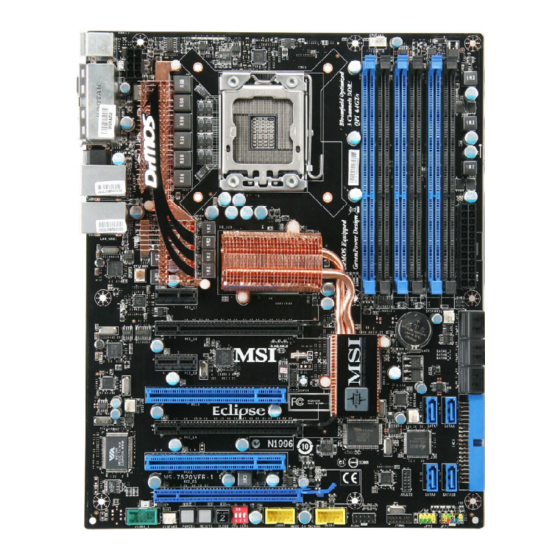
Page 13: Mainboard Layout
M S-7520 M ainboard Mainboard Layout Top : mouse CPUFAN Botto m: keyboard Top: USB por ts Botto m: 1394 port eSATA por ts CLR_COM S1 Top: LAN Jack2 Bottom: USB ports Top: LAN Jack1 Botto m: USB ports Intel SYSFAN4 RTL8111C JSM B1... -
Page 14: Packing Checklist
Getting Started Packing Checklist Back IO Shield MSI Driver/Utility CD MSI motherboard Power Cable SATA Cable IDE Cable CrossFire external SATA Cable USB Bracket Video Link Cable * The pictures are for reference only and may vary from the packing contents of the... - Page 15 M S-7520 M ainboard X-Fi Xtreme Audio Card D-LED2 Panel Set User’s Guide Set (Card and Driver CD) (1 panel & 1 cable) and Quick Guide GreenPower Genie Set (1 GreenPower genie & 1 power cable & 1 (2x2 pin) cable)
-
Page 16: Chapter 2. Hardware Setup
Hardware Setup Chapter 2 Hardware Setup This chapter provides you with the information about hardware setup procedures. While doing the installation, be careful in holding the components and follow the installation procedures. For some components, if you install in the wrong orientation, the components will not work properly. -
Page 17: Quick Components Guide
M S-7520 M ainboard Quick Components Guide SYSFAN2, p.2-21 SYSFAN4, p.2-21 CPUFAN, p.2-21 JPWR2, p.2-16 CPU, p.2-3 DDR3, p.2-7 Back Panel, p.2-17 JPWR1, p.2-16 SYSFAN3, p.2-21 JSMB1, p.2-24 PCI_E, p.2-26 SATA, p.2-20 JCI1, p.2-23 SYSFAN1, p.2-21 IDE1, p.2-19 PCI, p.2-29 SATA, p.2-20 JDLED2, p.2-23 J1394_1,... -
Page 18: Cpu (Central Processing Unit)
W hen you are installing the CPU, make sure to install the cooler to prevent overheating. If you do not have the CPU cooler, consult your dealer before turning on the computer. For the latest information about CPU, please visit http://global.msi.com.tw/index.php? func=cpuform2 Important Overheating Overheating will seriously damage the CPU and system. - Page 19 M S-7520 M ainboard CPU & Cooler Installation W hen you are installing the CPU, make sure the CPU has a cooler attached on the top to prevent overheating. Meanwhile, do not forget to apply some thermal paste on CPU before installing the heat sink/cooler fan for better heat dispersion. Follow the steps below to install the CPU &...
- Page 20 Hardware Setup 5. Visually inspect if the CPU is seated 6. C over t h e l oad p l at e on t o t h e well into the socket. If not, take out package. the CPU with pure vertical motion and reinstall.
- Page 21 M S-7520 M ainboard 9. Align the holes on the mainboard with 10. Turn over the mainboard to confirm the heatsink. Push down the cooler that the c lip-ends are c orrectly until its four clips get wedged into inserted. the holes of the mainboard.
-
Page 22: Memory
Hardware Setup Memory These DIMM slots are used for installing memory modules. For more information on compatible components, please visit http://global.msi.com. tw/index.php?func=testreport DDR3 240-pin, 1.5V 48x2=96 pin 72x2=144 pin Memory Population Rules Please refer to the following illustrations for memory population rules. - Page 23 M S-7520 M ainboard Three-Channel mode In Three-Channel mode, the memory modules can transmit and receive data with three data bus lines simultaneously. Enabling Three-Channel mode can enhance the best system performance. W hen you have three or more memory modules, please always insert them as the way 3/ 4/ 5/ 6 (shown in below) to get the best system performance.
- Page 24 Hardware Setup Important - DDR3 memory modules are not interchangeable with DDR2 and the DDR3 standard is not backwards compatible. You should always install DDR3 memory modules in the DDR3 DIMM slots. - In Three-/ Dual- channel mode, make sure that you install memory modules of the same type and density in different channel DIMM slots.
-
Page 25: Installing Memory Modules
M S-7520 M ainboard Installing Memory Modules 1. The memory module has only one notch on the center and will only fit in the right orientation. 2. Insert the memory module vertically into the DIMM slot. Then push it in until the golden finger on the memory module is deeply inserted in the DIMM slot. - Page 26 Hardware Setup Compatible DDR3 800 memory list Please refer to the following list to find the available DDR3 800 memory modules. Vendor Model Size Memory slot A1 A0 B1 B0 C1 C0 Qimonda IMSH51U03A1F1C-08E(Qimonda IDSH51-03A1F1C-08E) 512MB M378B6573EZ0-CF-7(SEC K4B510846E-ZCF7) 512MB V V V V Compatible DDR3 1066 memory list Please refer to the following list to find the available DDR3 1066 memory modules.
- Page 27 M S-7520 M ainboard Vendor Model Size Memory slot A1 A0 B1 B0 C1 C0 Micron MT8JTF12864AY-1G1D1(Micron D9JNL) Qimonda IMSH1GU03A1F1C-10G(Qimonda IDSH1G-03A1F1C-10G) Qimonda IMSH1GU03A1F1C-10F (Qimonda IDSH1G-03A1F1C-10F) Qimonda IMSH1GU13A1F1C-10F (Qimonda IDSH51-03A1F1C-10F) V V V V Qimonda IMSH1GU13A1F1C-10G (Qimonda IDSH51-03A1F1C-10G) V V V V M378B2873DZ1-CF8 (SEC K4B1G0846D-HCF8) Supertalent W1066UA1GS (SEC K4B1G0846C-ZCF8)
- Page 28 Hardware Setup Vendor Model Size Memory slot A1 A0 B1 B0 C1 C0 Aeneon Aeneon AEH660UD00-10FA98X (Aeneon AEH93R10F) 512MB ELPIDA EBJ51UD8BAFA-AC-E (ELPIDA J5308BASE) 512MB V V V V Qimonda IMSH51U03A1F1C-10F (Qimonda IDSH51-03A1F1C-10F) 512MB V V V V Qimonda IMSH51U03A1F1C-10G (Qimonda IDSH51-03A1F1C-10G) 512MB V V V V ADATA...
- Page 29 M S-7520 M ainboard Vendor Model Size Memory slot A1 A0 B1 B0 C1 C0 TAKEMS TMS1GB364D081-107EQ (With iron case) Bufaullo D3/1066-2G (Micron D9GTR) Crucial CT25664BA1067.16SFD (Micron D9JNL) HYNIX HMT125U6AFP8C-G7N0 (Hynix H5TQ1G83AFP-G7C) KINGSTON KVR1066D3N7/2G (SEC K4B1G0846C-ZCF8) V V V V V V Micron MT16JTF25664AY-1G1D1 (Micron D9JNL )...
- Page 30 V V V V V V KINGSTON KVR1333D3N9/2G (Elpida J1108BASE-DJ-E) V V V V V V Micron MT16JTF25664AY-1G4D1 (Micron D9JNM) Qimonda IMSH2GU13A1F1C-13H (Qimonda IDSH1G-03A1F1C-13H) M378B5673CZ0-CH9 (SEC K4B1G0846C-ZCH9) M378B5673DZ1-CH9 (SEC K4B1G0846D-HCH9) Important For more information on compatible components, please visit http://global. msi.com.tw/index.php?func=testreport. 2-15...
-
Page 31: Power Supply
M S-7520 M ainboard Power Supply ATX 24-Pin Power Connector: JPWR1 pin 13 This connector allows you to connect an ATX 24-pin power supply. To connect the ATX 24-pin power supply, make sure the plug of the power supply is inserted in the proper orientation and the pins are aligned. -
Page 32: Back Panel
Hardware Setup Back Panel USB Ports Mouse Keyboard USB Ports eSATA Ports USB Ports 1394 Port Clear CMOS Button M ouse/Keyboard ® ® The standard PS/2 mouse/keyboard DIN connector is for a PS/2 mouse/keyboard. 1394 Port The IEEE1394 port on the back panel provides connection to IEEE1394 devices. USB Port The USB (Universal Serial Bus) port is for attaching USB devices such as keyboard, mouse, or other USB-compatible devices. - Page 33 M S-7520 M ainboard The standard RJ-45 LAN jack is for connection Yellow Green / Orange to the Local Area Network (LAN). You can con- nect a network cable to it. Color LED State Condition LAN link is not established. Left Yellow On (steady state)
-
Page 34: Connectors
Hardware Setup Connectors IDE Connector: IDE1 This connector supports IDE hard disk drives, optical disk drives and other IDE devices. Important If you install two IDE devices on the same cable, you must configure the drives separately to master / slave mode by setting jumpers. Refer to IDE dev ic e’s doc umentation s upplied by the vendors for jumper s etting instructions. - Page 35 M S-7520 M ainboard Serial ATA Connector: SATA1~10 This connector is a high-speed Serial ATA interface port. Each connector can connect to one Serial ATA device. SATA1~6 stack SATA connectors are supported by ICH10R SATA1_3 SATA2_4 SATA5_6 SATA7 & 8 are controlled SATA7 SATA8 by 1st JMB322...
- Page 36 Hardware Setup Fan Power Connectors: CPUFAN, SYSFAN1~5 The fan power connectors support system cooling fan with +12V. W hen connecting the wire to the connectors, always note that the red wire is the positive and should be connected to the +12V; the black wire is Ground and should be connected to GND. If the mainboard has a System Hardware Monitor chipset on-board, you must use a specially designed fan with speed sensor to take advantage of the CPU fan control.
-
Page 37: Front Panel Connectors: Jfp1/2
M S-7520 M ainboard Front Panel Connectors: JFP1, JFP2 These connectors are for electrical connection to the front panel switches and LEDs. ® The JFP1 is compliant with Intel Front Panel I/O Connectivity Design Guide. JFP1 Pin Definition SIGNAL DESCRIPTION Power Power Switch... - Page 38 Hardware Setup TPM Module Connector: JTPM1 This connector connects to a TPM (Trusted Platform Module) module (optional). Please refer to the TPM security platform manual for more details and usages. Signal Description Signal Description LCLK LPC clock 3V_STB 3V standby power LRST# LPC reset VCC3...
- Page 39 M S-7520 M ainboard Front USB Connector: JUSB1/ JUSB2 ® These connectors, compliant with Intel I/O Connectivity Design Guide, is ideal for connecting high-speed USB interface peripherals such as USB HDD, digital cameras, M P3 players, printers, modems and the like. Pin Definition SIGNAL SIGNAL...
-
Page 40: Buttons
Hardware Setup Buttons The motherboard provides the following buttons for you to set the computer’s function. This section will explain how to change your motherboard’s function through the use of button. Power Button: POWER1 This power button is used to turn-on or turn-off the system. Press the button to turn- on or turn-off the system. -
Page 41: Slots
M S-7520 M ainboard Slots PCI (Peripheral Component Interconnect) Express Slot The PCI Express slot supports the PCI Express interface expansion card. The PCI Express 2.0 x16 supports up to 8.0 GB/s transfer rate. The PCI Express 2.0 x4 supports up to 2.0 GB/s transfer rate. The PCI Express x1 supports up to 250 MB/s transfer rate. - Page 42 Hardware Setup ATI CrossFireX (Multi-GPU) Technology ATI CrossFireX (Multi-GPU) technology is an exciting new technology developed by ATI that allows the power of multiple Graphics. CrossFireX requires a CrossFireX Edition graphics card and the compatible standard (CrossFireX Ready) graphics card from the same series.
- Page 43 M S-7520 M ainboard 3.W hen all of the hardware and software has been properly set up and installed, reboot the system. After entering the O.S., click the “Catalyst™ Control Center” icon on the desktop. There is a setting in the Catalyst™ Control Center that needs to be enabled for CrossFire™...
-
Page 44: Pci Interrupt Request Routing
Hardware Setup PCI (Peripheral Component Interconnect) Slot The PCI slot supports LAN card, SCSI card, USB card, and other add-on cards that comply with PCI specifications. 32-bit PCI Slot Important When adding or removing expansion cards, make sure that you unplug the power supply first. -
Page 45: Switch
M S-7520 M ainboard Switch Hardware Overclock Base clock Switch: CPU_CLK1 You can overclock the Base clock to increase the processor frequency by changing this switch. Follow the instructions below to set the CPU clock. 1 2 3 1 2 3 1 2 3 133 MHz (default) 166 MHz... -
Page 46: Led Status Indicators
Hardware Setup LED Status Indicators DIMM warning LED CPU Phase LE Ds DDR Phase LEDs QPI Phase LEDs IOH Phase LEDs PCIE LED PCIE LED PCIE LED PCI LED PCIE LED PCI LED Power LED PCIE LED Standby LED 1 2 3 2-31... - Page 47 M S-7520 M ainboard Name Status CPU Phase LEDs 6/ 5/ 4/ 3/ 2/ 1 of the LEDs will light blue when CPU is in 6/ 5/ 4/ 3/ 2/ 1 phase power mode. QPI Phase LEDs 2/ 1 of the LEDs will light blue when QPI is in 2/ 1 phase power mode.
-
Page 48: Chapter 3 Bios Setup
BIOS Setup Chapter 3 BIOS Setup This chapter provides information on the BIOS Setup program and allows you to configure the system for optimum use. You may need to run the Setup program when: ² An error message appears on the screen during the system booting up, and requests you to run SETUP. -
Page 49: Entering Setup
M S-7520 M ainboard Entering Setup Power on the computer and the system will start POST (Power On Self Test) process. W hen the message below appears on the screen, press <DEL> key to enter Setup. Press DEL to enter SETUP If the message disappears before you respond and you still wish to enter Setup, restart the system by turning it OFF and On or pressing the RESET button. -
Page 50: Control Keys
BIOS Setup Control Keys < ↑> Move to the previous item < ↓> Move to the next item < ←> Move to the item in the left hand < →> Move to the item in the right hand Select the item <Enter>... -
Page 51: The Main Menu
M S-7520 M ainboard The Main Menu Standard CM OS Features Use this menu for basic system configurations, such as time, date etc. Advanced BIOS Features ® Use this menu to setup the items of AMI special enhanced features. Integrated Peripherals Use this menu to specify your settings for integrated peripherals. - Page 52 BIOS Setup User Settings Use this menu to save/ load your settings to/ from CMOS for BIOS. M-Flash Use this menu to read/ flash the BIOS from storage drive (FAT/ FAT32 format only). Load Fail-Safe Defaults Use this menu to load the default values set by the BIOS vendor for stable system performance.
-
Page 53: Standard Cmos Features
M S-7520 M ainboard Standard CMOS Features The items in Standard CMOS Features Menu includes some basic setup items. Use the arrow keys to highlight the item and then use the <PgUp> or <PgDn> keys to select the value you want in each item. Date (MM:DD:YY) This allows you to set the system to the date that you want (usually the current date). -
Page 54: System Information
BIOS Setup Device / Vendor / Size It will showing the device information that you connected to the SATA connector. Important IDE Primary Master/ Slave, SATA1~6 & 7/8 & 9/10 & E-SATA1/2 are appearing when you connect the HD devices to the IDE/ SATA connector on the mainboard. -
Page 55: Advanced Bios Features
M S-7520 M ainboard Advanced BIOS Features BIOS Flash Protection W hen enabled, the BIOS’ data cannot be changed when attempting to update the BIOS with a Flash utility. To successfully update the BIOS, you’ll need to disable this Flash BIOS Protection function. You should enable this function at all times. The only time when you need to disable it is when you want to update the BIOS. - Page 56 BIOS Setup MPS Table Version This field allows you to select which MPS (Multi-Processor Specification) version to be used for the operating system. You need to select the MPS version supported by your operating system. To find out which version to use, consult the vendor of your operating system.
-
Page 57: Trusted Computing
M S-7520 M ainboard Chipset Feature Press <Enter> to enter the sub-menu and the following screen appears: HPET The HPET (High Precision Event Timers) is a component that is part of the chipset. You can to enable it, and will provide you with the means to get to it via the various ACPI methods. -
Page 58: Integrated Peripherals
BIOS Setup Integrated Peripherals USB Controller This setting allows you to enable/disable the onboard USB controller. USB Device Legacy Support Select [Enabled] if you need to use a USB-interfaced device in the operating system. Onboard LAN/ 2nd LAN Controller This item is used to enable/disable the onboard 1st/ 2nd LAN controller. LAN Option ROM This item is used to decide whether to invoke the Boot ROM of the LAN controller. - Page 59 M S-7520 M ainboard Drive Booster Controller #1 (for SATA7 & 8)/ #2(for SATA9 & 10) Press <Enter> to enter the sub-menu, and the following screen appears. Current M ode This item shows the current SATA mode. Read only. Drive Booster M ode Update: Update To RAID0 (Stripe)/ RAID1(Mirror)/ JBOD(Large)/ Normal Hdd These items are used to enable the RAID0/ RAID1/ JBOD/ Normal (non-RAID) mode for the SATA devices.
- Page 60 BIOS Setup AHCI CD/DVD Boot Time out Select the waiting time for the AHCI CD/ DVD when booting. AHCI Port 1/2/3/4/5/6 Press <Enter> to enter the sub-menu. AHCI Port 1/2/3/4/5/6 Select the type of device. I/O Device Press <Enter> to enter the sub-menu and the following screen appears: COM Port 1 Select an address and corresponding interrupt for the first serial port.
-
Page 61: Power Management Setup
M S-7520 M ainboard Power Management Setup Important S3-related functions described in this section are available only when your BIOS supports S3 sleep mode. ACPI Function This item is to activate the ACPI (Advanced Configuration and Power Management Interface) Function. If your operating system is ACPI-aware, such as W indows 2000/ XP, select [Enabled]. - Page 62 BIOS Setup Re-Call VGA BIOS From S3 W hen ACPI Standby State is set to [S3], users can select the options in this field. Selecting [Yes] allows BIOS to call VGABIOS to initialize the VGA card when system wakes up (resumes) from S3 sleep state. The system resume time is shortened when you disable the function, but system will need an VGA driver to initialize the VGA card.
- Page 63 M S-7520 M ainboard Resume by PCI-E Device W hen set to [Enabled], the feature allows your system to be awakened from the power saving modes through any event on PCI-E device. Resume by RTC Alarm The field is used to enable or disable the feature of booting up the system on a scheduled time/date.
-
Page 64: H/W Monitor
BIOS Setup H/W Monitor Chassis Intrusion The field enables or disables the feature of recording the chassis intrusion status and issuing a warning message if the chassis is once opened. To clear the warning message, set the field to [Reset]. The setting of the field will automatically return to [Enabled] later. -
Page 65: Green Power
M S-7520 M ainboard Green Power CPU Phase Control W hen set to [Auto], the hardware will auto adjust the CPU power phase according to the loading of CPU to reach the best power saving function. QPI Phase Control W hen set to [Auto], the hardware will auto adjust the QPI power phase to reach the best power saving function. -
Page 66: Bios Setting Password
BIOS Setup BIOS Setting Password W hen you select this function, a message as below will appear on the screen: Type the password, up to six characters in length, and press <Enter>. The password typed now will replace any previously set password from CMOS memory. You will be prompted to confirm the password. -
Page 67: Cell Menu
M S-7520 M ainboard Cell Menu Important Change these settings only if you are familiar with the chipset. Current Core / DRAM / QPI Frequency These items show the current clocks of CPU and Memory speed. Read-only. 3-20... - Page 68 BIOS Setup CPU Specifications Press <Enter> to enter the sub-menu and the following screen appears. This sub-menu displays the informations of installed CPU. CPU Technology Support Press <Enter> to enter the sub-menu and the following screen appears. This sub-menu displays the technologies that the installed CPU supported. Intel EIST The Enhanced Intel SpeedStep technology allows you to set the performance level of the microprocessor whether the computer is running on battery or AC power.
- Page 69 M S-7520 M ainboard Base Clock (MHz) This item allows you to set the CPU Base clock (in MHz). You may overclock the CPU by adjusting this value. Please note the overclocking behavior is not guaranteed. Intel Turbo Boost tech This item will appear when you install a CPU with Intel Turbo Boost technology.
- Page 70 BIOS Setup Adjusted CPU Frequency (M Hz) It shows the adjusted CPU frequency (Base clock x Ratio). Read-only. QPI Configuration Press <Enter> to enter the sub-menu and the following screen appears. QPI Links Speed This item allows you to select the QPI links speed type. QPI Frequency This item allows you to select the QPI frequency.
- Page 71 M S-7520 M ainboard Advance DRAM Configuration Press <Enter> to enter the sub-menu and the following screen appears. 1N/2N M emory Timing This item controls the SDRAM command rate. Select [1N] makes SDRAM signal controller to run at 1N (N=clock cycles) rate. Selecting [2N] makes SDRAM signal controller run at 2N rate.
- Page 72 BIOS Setup Adjusted DRAM Frequency (MHz) It shows the adjusted DDR Memory frequency. Read-only. ClockGen Tuner Press <Enter> to enter the sub-menu and the following screen appears. CPU / PCI Express Amplitude Control These items are used to select the CPU/ PCI Express clock amplitude. CPU CLK Skew/ IOH CLK Skew These items are used to select the CPU/ IOH chipset clock skew.
-
Page 73: Spread Spectrum
M S-7520 M ainboard Spread Spectrum W hen the motherboard’s clock generator pulses, the extreme values (spikes) of the pulses create EMI (Electromagnetic Interference). The Spread Spectrum function reduces the EMI generated by modulating the pulses so that the spikes of the pulses are reduced to flatter curves. -
Page 74: Cpu And Memory Clock Overclocking
BIOS Setup CPU and Memory Clock Overclocking The D.O.T Control, Base Clock, Memory Ratio items for you to overclock the CPU and the Memory. Please refer to the descriptions of these fields for more information. Important 1. CPU Speed = Base clock * CPU Ratio 2. -
Page 75: User Settings
M S-7520 M ainboard User Settings Save Settings 1/ 2/ 3/ 4 These items are used to save the settings set by yourself to CMOS. Load Settings 1/ 2/ 3/ 4 These items are available after you save your settings in Save Settings 1/ 2/ 3/ 4 items , and are used to load the settings from CMOS. -
Page 76: M-Flash
BIOS Setup M-Flash == BIOS Update or Load BIOS From USB drive== M -Flash function as M-Flash funcion allows you to flash BIOS from USB drive/ storage drive (FAT/ FAT32 format only), or allows the system to boot from the BIOS file inside USB drive (FAT/ FAT32 format only). - Page 77 M S-7520 M ainboard Important 1. Please refer to the block diagram below about the M-Flash function. Set [BIOS Update] or [USB Drive] in "M-Flash function as" field Select BIOS file from the root directory of USB/ Storage drive (FAT/FAT32 format only) in "Load BIOS source file from"...
- Page 78 BIOS Setup == BIOS Data Saving == The following fields are used to read the onboard BIOS ROM data, and save it to USB drive/ storage drive. Save File to Selected Device Please setup a specific folder in specific USB drive/ storage drive to save BIOS file from BIOS ROM chip data.
-
Page 79: Load Fail-Safe/ Optimized Defaults
M S-7520 M ainboard Load Fail-Safe/ Optimized Defaults The two options on the main menu allow users to restore all of the BIOS settings to the default Fail-Safe or Optimized values. The Optimized Defaults are the default values set by the mainboard manufacturer specifically for optimal performance of the mainboard. -
Page 80: Appendix A X-Fi Xtreme Audio Card
X-Fi Xtreme Audio Card Appendix A X-Fi Xtreme Audio Card The X-Fi Xtreme Audio card is powered by Creative CA0110 Audio chip. It supports up to 8-channel & SPDIF audio effect and allows users to attach 2, 4, 6, or 8 speakers for better surround sound effect. -
Page 81: Introduction
M S-7520 M ainboard Introduction X-Fi Xtreme Audio Card is powered by Creative CA0110 Digital Audio Controller. This card provides advanced audio functions by offering a comprehensive suite of software applications. The advanced tools and amazing features provided will allow you to experience a full array of exciting activities, such as listening to effects enhanced music, watching a multi-channel movie, playing the latest game or recording a high quality audio track. - Page 82 X-Fi Xtreme Audio Card Features High Definition Audio Quality - 144-pin LQFP ASIC with 64 audio channel playback at independent sample rates - 24-bit Analog-to-Digital conversion of analog inputs at 96kHz sample rate - 24-bit Digital-to-Analog conversion of digital sources at 96kHz to analog 7.1 speaker output - 16-bit and 24-bit recording with sampling rates of 8, 11.025, 16, 22.05, 24, 32, 44.1, 48 and 96kHz...
-
Page 83: Hardware Installation
M S-7520 M ainboard Hardware Installation Installing the Card The interface of X-Fi Xtreme Audio Card is PCI-E x1. You can install it to the PCI-E slot. Follow the steps below to install the card, then you can activate the advanced function and enjoy the audio effect. - Page 84 X-Fi Xtreme Audio Card Connecting the Speakers W hen you have set the Multi-Channel Audio Function mode properly in the software utility, connect your speakers to the correct jacks in accordance with the setting in software utility. n 2-Channel M ode for 2-Speaker Output Refer to the diagram and caption for the function of each jack on the back panel when 2-Channel Mode is selected.
- Page 85 M S-7520 M ainboard n 6-Channel M ode for 6-Speaker Output Refer to the diagram and caption for the function of each jack on the back panel when 6-Channel Mode is selected. 6-Channel Analog Audio Output 1 S/PDIF Out-Optical 2 MIC & Line-In 3 Line Out (Front channels) 4 No function 5 Line Out (Center and Subwoofer channel)
-
Page 86: Installing The Creative Audio Driver
X-Fi Xtreme Audio Card Installing the Creative Audio Driver You need to install the driver for Creative CA0110 to function properly before you can get access to 2-, 4-, 6- or 8- channel and SPDIF audio operations. Follow the proce- dures below to install the drivers for W indows 2000/ XP/ VISTA operating system. - Page 87 M S-7520 M ainboard 3. Select your region from the list . 4. Select the language that you need from the list . 5. On the next page, click Install to start the installation and follow the setup instruc- tions to complete. 6.
-
Page 88: Software Configuration
X-Fi Xtreme Audio Card Software Configuration After installing the creative audio driver, you are able to use the 2-, 4-, 6- or 8- channel and the SPDIF audio features. Double click on the creative volume control audio icon from the system tray at the lower-right corner of the screen to activate the Sound Blaster X-Fi Xtreme Audio Applications, simply click on each icon to enter the configuration screen. - Page 89 M S-7520 M ainboard Creative M ediaSource Go! Launcher Click on the Creative MediaSource Go! Launcher icon to enter its configuraton screen. Creatvie MediaSource Go! Launcher consists of various tabs such as Programs, Product Settings, Product Support and Companion Products. In each tab, you can access different applications, called Tasks.
- Page 90 X-Fi Xtreme Audio Card Soundfont Bank Manager Click on the SOUNDFONT BANK MANAGER icon to enter its configuraton screen. ® W ith SoundFont Bank Manager (SFBM), you can: click on this button to get the online help information - Load SoundFont banks Replace the default sounds on your computer with the high-quality sound of a SoundFont bank.
- Page 91 M S-7520 M ainboard Creative MediaSource Play/ Organizer Click on the Creative MediaSource Play/ Organizer icon to enter its configuraton screen. Creative MediaSource Player/ Oraganizer is your digital music center for playing , creating, organizing and transferring digital music. This is your ultimate all-in-one digital entertainment software.
- Page 92 X-Fi Xtreme Audio Card Entertainment M ode Console Click on the Entertainment Mode icon to enter its configuraton screen. In Entertainment Mode, you audio device is optimized for movie soundtrack and music playback. You can configure Entertainment Mode settings in the Entertainment Mode consloe. W ith the Entertainment Mode console, you can: click on this button to get the online help information - Adjust master volume or speaker volume, bass and treble levels.
- Page 93 M S-7520 M ainboard The following table lists the function of each control on the main interface. Close button - Click on this button to close the Entertainment Mode console. Minimize button - Click on this button to minimize the Entertainment Mode window to the task bar.
- Page 94 X-Fi Xtreme Audio Card Speaker & Headphone Click on the speaker button to enter its configuration screen. Here you can adjust your speakers configuration. Select the type of your speaker system, and adjust the volume and cuff frequency for your subwoofer. This is the main application to use for the following tasks: - Designating the number and configuration of speakers to use =>...
- Page 95 M S-7520 M ainboard X-Fi CMSS-3D Click on the X-Fi CMSS-3D button to enter its configuration screen. Creative MultiSpeaker Surround (CMSS) 3D makes ordinary two-channel (Left and Right Stereo) sound seem to surround you, even through only two speakers. For users with 5.1, 6.1, 7.1 multichannel speaker systems, CMSS can also simulate surround sound from ordinary stereo.
-
Page 96: Appendix B Overclocking Center
Appendix B Overclocking Center Overclocking Center, the most useful and powerful utility that MSI has spent much research and efforts to develop, helps users to monitor or configure the hard- ware status of MSI Mainboard in windows, such as CPU clock, voltage, fan speed and temperature. -
Page 97: Activating Overclocking Center
M S-7520 M ainboard Activating Overclocking Center Once you have your Overclocking Center installed (locate the setup source file in the setup CD accompanying with your mainboard, path: Utility --> M SI Utility --> Overclocking Center), it will have a short cut icon on the desktop, and a short cut path in your “Start-up”... -
Page 98: System Info
Overclocking Center System Info In the System Info screen, you can read the informations of mainboard/ memory/ PCI. Motherboard Click Motherboard to read the informations of mainboard, mainboard BIOS, installed CPU and installed graphics card. - Page 99 M S-7520 M ainboard Memory Click Memory to read the information of each memory DIMM slot. You can select a DIMM slot you want to read from the SPD list. Click PCI to read the information of devices on the mainboard.
-
Page 100: Dot
Overclocking Center Click DOT to enter the DOT screen. In DOT, you can select the basic setting to reach optimal perf ormance in Basic menu or you c an adjus t advanced values for overclocking in Advance menu. Basic In the Basic menu, it provides one default setting and five common settings for different environments. - Page 101 M S-7520 M ainboard Advance In the Advance menu, you can adjust the values for each environment setting/ default setting. Click the Cooling/ Silence/ Default/ Game/ Cinema button to enter it’s setting menu. Please refer to the following descriptions to adjust the values and save them.
- Page 102 Overclocking Center In each setting menu, you can select desired values for manual overclocking. Simply click the right side of the button which arranges an arrow sign, and a drop-down menu will appear below the button, then select a value. Click the arrow sign and t he d rop- down m en u will appear.
- Page 103 M S-7520 M ainboard After you adjust the values in setting menu, you can save it for future use. Click the Save button, and enter a name in the empty box. Then, click Save button again to save the settings. Important It provides you to save up to 20 user settings.
-
Page 104: Appendix C Intel Ich10R Sata Raid
Intel ICH10R SATA RAID Appendix C Intel ICH10R SATA RAID This appendix will assist users in configuring and en- abling RAID functionality on platforms... -
Page 105: Introduction
M S-7520 M ainboard Introduction The ICH10R provides a hybrid solution that combines 6 independent SATAII ports for support of up to 6 Serial ATAII (Serial ATAII RAID) drives. Serial ATAII (SATAII) is the latest generation of the ATA interface. SATA hard drives deliver blistering transfer speeds up to 3 Gb/s. -
Page 106: Bios Configuration
Intel ICH10R SATA RAID BIOS Configuration The Intel Matrix Storage Manager Option ROM should be integrated with the system BIOS on all motherboards with a supported Intel chipset. The Intel Matrix Stroage Manager Option ROM is the Intel RAID implementation and provides BIOS and DOS disk services. - Page 107 M S-7520 M ainboard After pressing the <Ctrl> and <I> keys simultaneously, the following window will appear: (1) Create RAID Volume Select option 1 “Create RAID Volume” and press <Enter> key. The following screen appears. Then in the Name field, specify a RAID Volume name and then press the <TAB>...
- Page 108 Intel ICH10R SATA RAID In the Disk field, press <Enter> key and the following screen appears. Use <Space> key to select the disks you want to create for the RAID volume, then click <Enter> key to finish selection. Then select the strip value for the RAID array by using the “upper arrow” or “down arrow”...
- Page 109 M S-7520 M ainboard Important Since you want to create two volumes (Intel Matrix RAID Technology), this default size (maximum) needs to be reduced. Type in a new size for the first volume. As an example: if you want the first volume to span the first half of the two disks, re-type the size to be half of what is shown by default.
- Page 110 Intel ICH10R SATA RAID (2) Delete RAID Volume Here you can delete the RAID volume, but please be noted that all data on RAID drives will be lost. Important If your system currently boots to RAID and you delete the RAID volume in the Intel RAID Option ROM, your system will become unbootable.
- Page 111 M S-7520 M ainboard (3) Reset Disks to Non-RAID Select option 3 Reset Disks to Non-RAID and press <Enter> to delete the RAID volume and remove any RAID structures from the drives. The following screen appears: Press <Y> key to accept the selection. Important 1.
- Page 112 Intel ICH10R SATA RAID (4) Recovery Volume Options Select option 4 Recovery Volume Options and press <Enter> to change recovery volume mode. The following screen appears: Recovery mode will change from Continuous Update to On-Request after you enable “Only Recovery Disk” or “Only Master Disk”.
-
Page 113: Installing Driver
Please follow the instruction below to make an “Intel ® RAID Driver” for yourself. 1. Insert the MSI CD into the CD-ROM drive. 2. Click the “Browse CD” on the Setup screen. 3. Copy all the contents in \\IDE\Intel\ICH10R\Floppy to a formatted floppy diskette. - Page 114 Intel ICH10R SATA RAID † Existing Windows Vista/XP Driver Installation 1. Insert the MSI CD into the CD-ROM drive. 2. The CD will auto-run and the setup screen will appear. 3. Under the Driver tab, click on Intel IAA RAID Edition.
-
Page 115: Installing Software
For this reason, you cannot remove or un-install this driver from the system after installation; however, you will have the ability to un-install all other non-driver components. Insert the MSI CD and click on the Intel IAA RAID Editor to install the software. Click on this item C-12... - Page 116 Intel ICH10R SATA RAID The InstallShield Wizard will begin automatically for installation showed as following: Click on the Next button to proceed the installation in the welcoming window. C-13...
- Page 117 M S-7520 M ainboard The window shows the components to be installed. Click Next button to continue. After reading the license agreement in the following window, click Yes button to continue. C-14...
- Page 118 Intel ICH10R SATA RAID The following window appears to show the Readme File Information. It shows the system requirements and installation information. Once the installation is complete, the following window appears. C-15...
-
Page 119: Raid Migration Instructions
M S-7520 M ainboard RAID Migration Instructions The Intel Matrix Storage Console offers the flexibility to upgrade from a single Serial ATA (SATA) hard drive to RAID configuration when an additional SATA hard drive is added to the system. This process will create a new RAID volume from an existing disk. -
Page 120: Create Raid Volume From Existing Disk
Intel ICH10R SATA RAID Create RAID Volume from Existing Disk To create a RAID volume from an existing disk, choose Action --> Create RAID Volume from Existing Hard Drive. The Create RAID Volume from Existing Hard Drive Wizard pops up to lead you for the following procedure. - Page 121 M S-7520 M ainboard (1) Configure Volume Here you can configure the new RAID volume by entering the volume name, selecting the RAID level and strip size. RAID Volume Name: † A desired RAID volume name needs to be typed in where the ‘Volume_0000’ text currently appears above.
- Page 122 Intel ICH10R SATA RAID expensive (requiring read-in prior to write, in order to be able to calculate the correct parity information), or similar to RAID-1 writes. The write efficiency depends heavily on the amount of memory in the machine, and the usage pattern of the array.
- Page 123 M S-7520 M ainboard (3) Select Member Hard Drive(s) Then select the member disk (the target disk) that you wish to use and then click “- -->” to move it to the Selected field. Then click Next to continue. Please note that the existing data on the selected hard drive(s) will be deleted permanently.
- Page 124 Intel ICH10R SATA RAID (4) Specify Volume Size Specify the amount of available array space to be used by the new RAID volume. You may enter the amount in the space or use the slider to specify. It is recommended you use 100% of the available space for the optimized usage.
- Page 125 M S-7520 M ainboard (6) Start Migration The migration process may take up to two hours to complete depending on the size of the disks being used and the strip size selected. A dialogue window will appear stating that the migration process may take considerable time to complete, meanwhile a popup dialogue at the taskbar will also show the migration status.
-
Page 126: Recovery Volume Creation
Intel ICH10R SATA RAID Recovery Volume Creation A recovery volume can be created using either Basic mode or Advanced mode in the Intel Matrix Storage Console. Recovery Volume in Basic Mode Creation Important Creating a recovery volume will permanently delete any existing data on the drive selected as the recovery drive. - Page 127 M S-7520 M ainboard Recovery Volume in Advanced Mode Creation Important Creating a recovery volume will permanently delete any existing data on the drive selected as the recovery drive. Back up all important data before beginning these steps. To create a recovery volume in Advanced mode, use the following steps: (1) Open the Intel Matrix Storage Console.
- Page 128 Intel ICH10R SATA RAID (6) Select a hard drive to be used as the master hard drive for the recovery volume. (7) Select a hard drive to be used as the recovery hard drive for the recovery volume. C-25...
- Page 129 M S-7520 M ainboard (8) Select an update policy. (9) Select Finish to begin recovery volume creation. C-26...
-
Page 130: Degraded Raid Array
Intel ICH10R SATA RAID Degraded RAID Array A RAID 1, RAID 5 or RAID 10 volume is reported as degraded when one of its hard drive members fails or is temporarily disconnected, and data mirroring is lost. As a result, the system can only utilize the remaining functional hard drive member. To re- establish data mirroring and restore data redundancy, refer to the procedure below that corresponds to the current situation. - Page 131 M S-7520 M ainboard 5. Exit Intel RAID Option ROM, and then reboot to W indows system. 6. W hen prompted to rebuild the RAID volume, click 'Yes'. 7. The Intel(R) Storage Utility will be launched. Right-click the new hard drive and select 'Rebuild to this Disk'.
-
Page 132: Appendix Djmicron 362 Raid
JMicron RAID Appendix D JMicron 362 RAID This appendix will assist users in configuring and enabling RAID functionality on platforms. The JMicron RAID solution supports RAID level 0 (striping), RAID level 1 (mirroring) and J BOD (Concatenate). -
Page 133: Introduction
M S-7520 M ainboard Introduction JMicron JMB362 offers RAID level 0 (Striping), RAID level 1 (Mirroring and Duplexing) and JBOD (Concatenate) for E-SATA ports on this mainboard. RAID 0 breaks the data into blocks which are written to separate hard drives. Spreading the hard drive I/O load across independent channels greatly improves I/O performance. -
Page 134: Jmicron Raid Bios Utility
JMicron RAID JMicron RAID BIOS Utility Be sure to set RAID mode for the JMicron 36x ATA Controller in BIOS before configuring the JMicron BIOS utility. After that, save the configuration and exit. During boot up (POST), press CTRL+J to enter the JMicron BIOS RAID utility. The RAID Utility menu screen will be displayed. -
Page 135: Creating Raid Set
M S-7520 M ainboard Creating RAID set 1. Select “Create RAID Disk Drive”. Then press <Enter>. 2. Then in the Name field, specify a RAID set name and then press the <Enter> to go to the next field. 3. Choose a 0-Striped, a 1-Mirror, or a JBOD-Concatenate combination set and then press <Enter>... - Page 136 JMicron RAID 4. In the Hard Disk Disk List menu, use <Space> key to select the disks you want to create for the RAID set, then click <Enter> key to finish selection. 5. Then select the block value (stripe value) for the RAID array by using the “upper arrow”...
- Page 137 M S-7520 M ainboard 6. Then select the capacity of the RAID set in the Size field. The default value is the maximum capacity of the selected disks. Then press <Enter> to the Confirm Crea- tion field. 7. The Creation field will display a message to ask you to confirm the creation. Then press <Y>...
-
Page 138: Deleting Raid Set
JMicron RAID Deleting RAID set 1. Select “Delete RAID Disk Drive”. Then press <Enter>. 2. In the RAID Disk Driver List menu, use <Space> key to select the RAID set you want to delete. Then press <Del> key. 3. Press “Y” to accept the deletion when a deletion message is appeared. - Page 139 M S-7520 M ainboard Revert HDD to non-RAID Select Revert HDD to non-RAID and press <Enter>. In the Hard Disk Driver List menu use <Space> key to select the disks you want to revert then click <Enter> key. The following screen appears, press <Y> key to remove any RAID structures from the drives.
-
Page 140: Solving A Mirror Conflict
JMicron RAID Solving a Mirror Conflict A Mirror conflict occurs when both disks in a RAID 1 (Mirror) configuration are unplugged from the system in turn, then plugged in again. Since both disks contain exactly the same data, the system will be unable to determine which of the two is the source drive. -
Page 141: Rebuilding A Mirror Drive
M S-7520 M ainboard Rebuilding a Mirror drive W hen one of the disk in a RAID 1 (Mirror) configuration is unplugged from the system, then plugged in again, a dialogue box appears to ask you to rebuild the Mirror drive. Press <Y>... -
Page 142: Installing Driver
Please follow the instruction below to make an “JMicron RAID Driver” for yourself. 1. Insert the MSI CD into the CD-ROM drive. 2. Click the “Browse CD” on the Setup screen. 3. Copy all the contents in the \\IDE\JMicron\Floppy32 (for 32-bit OS) or \\IDE\JMicron\Floppy64 (for 64-bit OS) to a formatted floppy drive. - Page 143 M S-7520 M ainboard † Existing Windows Vista/XP Driver Installation 1. Insert the MSI CD into the CD-ROM drive. 2. The CD will auto-run and the setup screen will appear. 3. Under the Driver tab, click on JMicron JMB362 Drivers.
-
Page 144: Jmicron Raid Configurer
JMicron RAID JMicron Raid Configurer There is an application called JMRaidTool which helps you perform the following tasks of JMicron RAID. • Viewing RAID Array Configurations View an array configuration (mirrored, striped) • Creating RAID Arrays • Deleting a RAID Array •... -
Page 145: Create Raid
M S-7520 M ainboard Create RAID JMRaidTool supports the creation of RAID 0, 1 and JBOD. 1. Left-click the “Create Raid” button. 2. A CREATE RAID W IZARD dialogue will display on the screen, following the descrip- tion of every step to complete the creation. Create RAID from Existing Disk You can combine the Existing Disk (Source disk may content OS and Data) with other HD (must be larger than source Disk) to be RAID. - Page 146 JMicron RAID Remove RAID There are two ways you can choose to remove RAID. Way 1 1. Right-click the name of the disk array you want to delete and the “Remove” menu will appear. Select the “Remove Raid” of the pop-up menu. 2.
-
Page 147: Rebuild Raid
M S-7520 M ainboard Way2 1. Left-Click the “Remove Raid” icon on the toolbar. 2. A “REMOVE RAID” wizard dialogue will display on the screen, following the de- scription of every step to complete the deletion. Rebuild RAID RAID 1 can be rebuild while RAID 0, JBOD cannot be rebuild. There are two ways you can choose to rebuild RAID. - Page 148 JMicron RAID 2. Select “Rebuild Raid”. 3. A “REBUILD RAID W IZARD” dialogue will display on the screen, following the description of every step to complete the rebuilding. Way 2 1. If the disk array needs to rebuild then the rebuild button will be enabling on the toolbar.
-
Page 149: Solve Mirror Conflict
M S-7520 M ainboard 2. Left-Click the “Rebuild Raid” button on the toolbar. 3. A “REBUILD RAID W IZARD” dialogue will display on the screen, following the description of every step to complete the rebuilding. Solve Mirror Conflict If the conflict occurs, it will show the “REBUILDING RAID W IZARD” dialogue to ask you if you want to rebuild RAID, following the description of every step to rebuild the RAID. -
Page 150: Appendix E Drive Booster Manager
JMicron RAID Appendix E Drive Booster Manager This appendix will assist users in configuring and enabling RAID functionality on platform. The DRIVER BOOSTER MANAGER solution sup- ports RAID level 0 (striping), RAID level 1 (mirroring) and JBOD (Concatenate). -
Page 151: Introduction
M S-7520 M ainboard Introduction DRIVER BOOSTER MANAGER offers RAID level 0 (Striping), RAID level 1 (Mirroring and Duplexing)and JBOD (Concatenate) for SATA ports (SATA7/8 & SATA9/10) on this mainboard. RAID 0 breaks the data into blocks which are written to separate hard drives. Spreading the hard drive I/O load across independent channels greatly improves I/O performance. -
Page 152: Raid Configuration
JMicron RAID RAID Configuration There is an application called DRIVE BOOSTER MANAGER which helps you perform the following tasks of JMicron RAID. • Viewing SATA Drive informations • Creating RAID Arrays • Deleting RAID Installing the DRIVE BOOSTER MANAGER Follow the procedures described below to install the Drive Booster Manager. 1. - Page 153 M S-7520 M ainboard View SATA Drive Information Click the “Drive Booster Information” button and the information of all hard disks will display on the right side of the window. You may click the item “Controller”, you will find controller information. “Drive Booster I n f o r m a t i o n ”...
- Page 154 JMicron RAID Create RAID DRIVE BOOSTER MANAGER supports the creation of RAID 0, 1 and JBOD. 1. First, you have to choose a controller, that supports 2 SATA devices with RAID mode, in the Drive Booster Information screen. “Drive Booster I n f o r m a t i o n ”...
- Page 155 M S-7520 M ainboard 3. A warning message will appear to remind you that the data will be erased. Press the “Yes” if you really want to perform this creation. Important You will lose all data on the SATA drives when you perform this creation. Please ensure to back up all date in the SATA hard drives before performing this creation.
- Page 156 JMicron RAID Setup Password You may set a password for a volume. Click the “Change Password”, a screen will display. Please enter a new password in the “New Password” box,and enter the password again in the “confirm password” box to confirm the passsword. Then click Important A password is available for a volume only.
-
Page 157: Delete Raid
M S-7520 M ainboard Delete RAID 1. First, you have to choose a volume that you intend to delete RAID mode in the Drive Booster Information screen. 2. Click the “Drive Booster Configuration” button, and click the “Normal Mode” button. And then, click “Apply”... -
Page 158: Event Log
JMicron RAID 4. A warning will appear to inform you that the deletion is finished. Click “OK” to close the window. Event Log Click the “Event Log” button, all of the significant events will be listed. “E vent Log” button...