Table of Contents
Advertisement
Available languages
Available languages
Advertisement
Table of Contents

Related Manuals for MSI MS-7522


Summary of Contents for MSI MS-7522
- Page 1 X58A-GD65 series MS-7522 (v4.x) Mainboard G52-75221XC...
-
Page 2: Trademarks
Alternatively, please try the following help resources for further guidance. ◙ Visit the MSI website for FAQ, technical guide, BIOS updates, driver updates, and other information: http://www.msi.com/index.php?func=service ◙ Contact our technical staff at: http://ocss.msi.com... -
Page 3: Safety Instructions
MS-7522 MS-7522 Safety Instructions ■ Always read the safety instructions carefully. ■ Keep this User’s Manual for future reference. ■ Keep this equipment away from humidity. ■ Lay this equipment on a reliable flat surface before setting it up. ■... -
Page 4: Fcc-B Radio Frequency Interference Statement
VOIR LA NOTICE D’INSTALLATION AVANT DE RACCORDER AU RESEAU. Micro-Star International MS-7522 This device complies with Part 15 of the FCC Rules. Operation is subject to the follow- ing two conditions: this device may not cause harmful interference, and this device must accept any interference received, including interference that may cause undesired operation. -
Page 5: Weee (Waste Electrical And Electronic Equipment) Statement
MSI will comply with the product take back requirements at the end of life of MSI-branded prod- ucts that are sold into the EU. - Page 6 MSI će poštovati zahtev o preuzimanju ovakvih proizvoda kojima je istekao vek trajanja, koji imaju MSI oznaku i koji su prodati u EU. Ove proiz- vode možete vratiti na lokalnim mestima za prikupljanje.
- Page 7 MSI si adeguerà a tale Direttiva ritirando tutti i prodotti marchiati MSI che sono stati venduti all’interno dell’Unione Europea alla fine del loro...
-
Page 8: Table Of Contents
Preface Preface Contents Copyright Notice .................... ii Trademarks ....................ii Revision History..................... ii Technical Support..................ii Safety Instructions ..................iii FCC-B Radio Frequency Interference Statement.......... iv WEEE (Waste Electrical and Electronic Equipment) Statement ....v English ...................... En-1 Mainboard Specifications ...................En-2 Quick Components Guide ..................En-4 Screw Holes .......................En-5 CPU (Central Processing Unit) ................En-6... - Page 9 MS-7522 MS-7522 Français ..................... Fr-1 Spécifications ......................Fr-2 Guide Rapide Des Composants ................Fr-4 Trous Taraudés ....................Fr-5 Processeur : CPU ....................Fr-6 Mémoire ......................Fr-10 Connecteurs d’Alimentation ................Fr-13 Panneau arrière ....................Fr-14 Connecteurs ......................Fr-16 Bouton .......................Fr-22 Interrupteur ......................Fr-23 Emplacements ....................Fr-24 Indicateurs de Statut LED .................Fr-25 Réglage BIOS ....................Fr-26...
-
Page 11: English
English X58A-GD65 Series Europe version... -
Page 12: Mainboard Specifications
MS-7522 Mainboard Mainboard Specifications Processor Support ■ Intel i7 processor in the LGA1366 package ® (For the latest information about CPU, please visit http://www.msi.com/index. php?func=cpuform2) ■ Up to 6.4 GT/s Chipset ■ North Bridge : Intel X58 chipset ® ■... - Page 13 ■ ATX (24.4cm X 30.5 cm) Mounting ■ 9 mounting holes * If you need to purchase accessories and request the part numbers, you could search the product web page and find details on our web address below http://www.msi.com/index.php En-3...
-
Page 14: Quick Components Guide
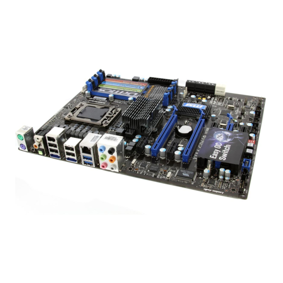
MS-7522 Mainboard Quick Components Guide DDR3, En-10 JPWR3, En-13 CPU, En-6 CPUFAN, En-17 Back Panel, En-14 JPWR1, En-13 SYSFAN1/3, En-17 PCIE, En-24 SATA1~8, En-16 PCI, En-24 SYSFAN2, JCOM1, En-17 En-17 JTPM1, En-20 JSP1, En-19 JCI1, En-18 JFP1, JFP2, En-20 RESET... -
Page 15: Screw Holes
Screw Holes When you install the mainboard, you have to place the mainboard into the chassis in the correct direction. The locations of screws holes on the mainboard are shown as below. The side has to toward the rear, the position for the I/O shield of the chassis. -
Page 16: Cpu (Central Processing Unit
When you are installing the CPU, make sure to install the cooler to prevent overheating. If you do not have the CPU cooler, consult your dealer before turning on the computer. For the latest information about CPU, please visit http://www.msi.com/index. php?func=cpuform2... - Page 17 CPU & Cooler Installation When you are installing the CPU, make sure the CPU has a cooler attached on the top to prevent overheating. Meanwhile, do not forget to apply some thermal paste on CPU before installing the heat sink/cooler fan for better heat dispersion. Follow the steps below to install the CPU &...
- Page 18 MS-7522 Mainboard Visually inspect if the CPU is seated Cover the load plate onto the pack- well into the socket. If not, take out age. the CPU with pure vertical motion and reinstall. Press down the load lever lightly onto...
- Page 19 Press the four hooks down to fasten Turn over the mainboard to confirm the cooler. that the clip-ends are correctly in- serted. Mainboard Hook Finally, attach the CPU Fan cable to the CPU fan connector on the main- board. Important •...
-
Page 20: Memory
MS-7522 Mainboard Memory These DIMM slots are used for installing memory modules. For more information on compatible components, please visit http://www.msi.com/index.php?func=testreport DDR3 240-pin, 1.5V 48x2=96 pin 72x2=144 pin Memory Population Rule Please refer to the following illustrations for memory population rules. - Page 21 Triple-Channel mode Population Rule In Triple-Channel mode, the memory modules can transmit and receive data with three data bus lines simultaneously. Enabling Triple-Channel mode can enhance the best system performance. When you have three or more memory modules, please always insert them as the figures shown in below.
-
Page 22: Installing Memory Modules
MS-7522 Mainboard To enable successful system boot-up, always insert the memory modules into the • DIMM_1 first. • Due to the chipset resource deployment, the system density will only be detected up to 23+GB (not full 24GB) when each DIMM is installed with a 4GB memory module. -
Page 23: Power Supply
Power Supply ATX 24-pin Power Connector: JPWR1 This connector allows you to connect an ATX 24-pin power supply. To connect the ATX 24-pin power supply, make sure the plug of the power supply is inserted in the proper orientation and the pins are aligned. Then push down the power supply firmly into the connector. -
Page 24: Back Panel
MS-7522 Mainboard Back Panel Coaxial S/PDIF-Out 1394 Port Clear CMOS Button Mouse USB 2.0 Port Line-In RS-Out Line-Out CS-Out Keyboard ESATA Port USB 3.0 Port SS-Out Optical S/PDIF-Out ▶ Mouse/Keyboard The standard PS/2 mouse/keyboard DIN connector is for a PS/2 mouse/keyboard. - Page 25 ▶ ESATA Port The ESATA (External SATA) port is for attaching the ESATA hard drive. ▶ USB 3.0 Port USB 3.0 port is backward-compatible with USB 2.0 devices. Supports data transfer rate up to 5 Gbit/s (SuperSpeed). Important If you want to use a USB 3.0 device, you must use the USB 3.0 cable to connect to the USB 3.0 port.
-
Page 26: Connectors
MS-7522 Mainboard Connectors Serial ATA Connector: SATA1~8 This connector is a high-speed Serial ATA interface port. Each connector can connect to one Serial ATA device. * The MB layout in this figure is for reference only. SATA1~6 (3Gb/s) SATA1_2 supported by Intel ICH10R ®... - Page 27 Fan Power Connectors: CPUFAN,SYSFAN1~3 The fan power connectors support system cooling fan with +12V. When connecting the wire to the connectors, always note that the red wire is the positive and should be con- nected to the +12V; the black wire is Ground and should be connected to GND. If the mainboard has a System Hardware Monitor chipset on-board, you must use a specially designed fan with speed sensor to take advantage of the CPU fan control.
- Page 28 MS-7522 Mainboard Front USB Connector: JUSB1~3 This connector, compliant with Intel I/O Connectivity Design Guide, is ideal for con- ® necting high-speed USB interface peripherals such as USB HDD, digital cameras, MP3 players, printers, modems and the like. * The MB layout in this figure is for reference only.
- Page 29 IEEE1394 Connector: J1394_1 This connector allows you to connect the IEEE1394 device via an optional IEEE1394 bracket. * The MB layout in this figure is for reference only. 1394 Bracket (optional) S/PDIF-Out Connector: JSP1 This connector is used to connect S/PDIF (Sony & Philips Digital Interconnect Format) interface for digital audio transmission.
- Page 30 MS-7522 Mainboard Front Panel Connectors: JFP1, JFP2 These connectors are for electrical connection to the front panel switches and LEDs. The JFP1 is compliant with Intel Front Panel I/O Connectivity Design Guide. ® JFP2 JFP1 TPM Module connector: JTPM1 This connector connects to a TPM (Trusted Platform Module) module (optional). Please refer to the TPM security platform manual for more details and usages.
- Page 31 Front Panel Audio Connector: JAUD1 This connector allows you to connect the front panel audio and is compliant with Intel ® Front Panel I/O Connectivity Design Guide. En-21...
-
Page 32: Buttons
MS-7522 Mainboard Buttons The mainboard provides the following buttons for you to set the computer’s function. This section will explain how to change your mainboard’s function through the use of button. Power Button This button is used to turn-on or turn-off the system. Press the button to turn-on or turn-off the system. -
Page 33: Switch
Switch This mainboard provides the following switch for you to set the computer’s function. This section will explain how to change your mainboard’s function through the use of switch. Hardware Overclock Base clock Switch: CPU_CLK1 You can overclock the Base clock to increase the processor frequency by changing this switch. -
Page 34: Slots
MS-7522 Mainboard Slots PCIE (Peripheral Component Interconnect Express) Slot The PCIE slot supports the PCIE interface expansion card. PCIE x16 Slot PCIE x1 Slot PCI (Peripheral Component Interconnect) Slot The PCI slot supports LAN card, SCSI card, USB card, and other add-on cards that comply with PCI specifications. -
Page 35: Led Status Indicators
LED Status Indicators APS LEDs RESET APS LEDs These APS (Active Phase Switching) LEDs indicate the current CPU power phase mode. Follow the instructions below to read. : Lights : Off CPU is in 1 phase power mode. CPU is in 2 phase power mode. CPU is in 3 phase power mode. -
Page 36: Bios Setup
MS-7522 Mainboard BIOS Setup This chapter provides basic information on the BIOS Setup program and allows you to configure the system for optimum use. You may need to run the Setup program when: ■ An error message appears on the screen during the system booting up, and requests you to run BIOS SETUP. -
Page 37: Entering Setup
Entering Setup Power on the computer and the system will start POST (Power On Self Test) process. When the message below appears on the screen, press <DEL> key to enter Setup. Press DEL to enter SETUP If the message disappears before you respond and you still wish to enter Setup, restart the system by turning it OFF and On or pressing the RESET button. - Page 38 MS-7522 Mainboard The Main Menu Once you enter BIOS CMOS Setup Utility, the Main Menu will appear on the screen. The Main Menu allows you to select from the setup functions and two exit choices. Use arrow keys to select among the items and press <Enter> to accept or enter the sub-menu.
- Page 39 ▶ User Settings Use this menu to save/ load your settings to/ from CMOS for BIOS. ▶ M-Flash Use this menu to read/ flash the BIOS from storage drive (FAT/ FAT32 format only). ▶ Load Fail-Safe Defaults Use this menu to load the default values set by the BIOS vendor for stable system performance.
- Page 40 Select [Ok] and press Enter to save the configurations and exit BIOS Setup utility. Important The configuration above are for general use only. If you need the detailed settings of BIOS, please see the complete version of English manual on MSI website. En-30...
- Page 41 Cell Menu Introduction : This menu is for advanced user who want to overclock the mainboard. Important Change these settings only if you are familiar with the chipset. ▶ Current CPU / DRAM / QPI Frequency These items show the current frequencies of CPU, Memory and QPI. Read-only. ▶...
- Page 42 MS-7522 Mainboard ▶ C State package limit setting This field allows you to select a C-state level. We recommend that you leave this setting to Auto. ▶ C1E Support To enable this item to read the CPU power consumption while idle. Not all processors support Enhanced Halt state (C1E).
- Page 43 I/O (VT-d). For further information please refer to Intel’s official website. ▶ Intel EIST The Enhanced Intel SpeedStep technology allows you to set the performance level of the microprocessor whether the computer is running on battery or AC power. This field will appear after you installed the CPU which supports speedstep technology.
- Page 44 MS-7522 Mainboard ▶ Current DRAM Channel Timing It shows the installed DRAM Timing. Read-only. ▶ DRAM Timing Mode Select whether DRAM timing is controlled by the SPD (Serial Presence Detect) EE- PROM on the DRAM module. Setting to [Auto] enables DRAM timings and the following “Advance DRAM Configuration”...
- Page 45 ▶ CH1/ CH2/ CH3 tRTP Time interval between a read and a precharge command. ▶ CH1/ CH2/ CH3 tFAW This item is used to set the tFAW timing. ▶ Current CH1/ CH2/ CH3 tdrRdTRd/ tddRdTRd/ tsrRdTWr/ tdrRdTWr/ tddRdTWr/ tsrWrTRd/ tddWrTWr/ tsrRDTRd/ tsrWrTWr These item show the advanced DRAM timings.
- Page 46 MS-7522 Mainboard ▶ CPU Voltage (V)/ CPU PLL Voltage (V)/ QPI Voltage (V)/ DRAM Voltage (V)/ DDR_ VREF_CA_A (V)/ DDR_VREF_CA_B (V)/ DDR_VREF_CA_C (V)/ DDR_VREF_DQ_A (V)/ DDR_VREF_DQ_B (V)/ DDR_VREF_DQ_C (V)/ IOH Voltage (V)/ ICH Voltage (V) These items are used to adjust the voltage of CPU, Memory and chipset.
- Page 47 Important Failed Overclocking Resolution This mainboard supports overclocking greatly. However, please make sure your peripherals and components are bearable for some special settings. Any operation that exceeds product specification is not recommended. Any risk or damge resulting from improper operation will not be under our product warranty. Two ways to save your system from failed overclocking...
-
Page 48: Software Information
Driver menu : The Driver menu shows the available drivers. Install the driver by your desire and to activate the device. Utility menu : The Utility menu shows the software applications that the mainboard supports. Important Please visit the MSI website to get the latest drivers and BIOS for better system performance. En-38... -
Page 49: Deutsch
Deutsch X58A-GD65 Serie Europe version... -
Page 50: Spezifikationen
MS-7522 Mainboard Spezifikationen Prozessoren ■ Intel i7 Prozessoren für Sockel LGA1366 ® (Weitere Informationen finden unter http://www.msi.com/index. php?func=cpuform2) ■ Bis zu 6.4 GT/s Chipsatz ■ North-Bridge : Intel X58 Chipsatz ® ■ South-Bridge : Intel ICH10R Chipsatz ® Speicher ■... - Page 51 3 PCIE 2.0 x16-Steckplätze ■ 2 PCIE 2.0 x1-Steckplätze ■ 2 PCI-Steckplätze Form Faktor ■ ATX (24,4cm X 30,5 cm) Montage ■ 9 Montagebohrungen * Wenn Sie für Bestellungen von Zubehör Teilenummern benötigen, finden Sie diese auf unserer Produktseite unter http://www.msi.com/index.php De-3...
-
Page 52: Komponenten-Übersicht
MS-7522 Mainboard Komponenten-Übersicht DDR3, De-10 JPWR3, De-13 CPU, De-6 CPUFAN, De-17 Rücktafel, De-14 JPWR1, De-13 SYSFAN1/3, De-17 PCIE, De-24 SATA1~8, De-16 PCI, De-24 SYSFAN2, JCOM1, De-17 De-17 JTPM1, De-20 JSP1, De-19 JCI1, De-18 JFP1, JFP2, De-20 RESET JAUD1, De-21 JUSB1~3, De-18... -
Page 53: Schraubenlöcher
Schraubenlöcher Wenn Sie das Mainboard zu installieren, müssen Sie das Mainboard in das Chassis in der korrekten Richtung setzen. Die Standorte von Schraubenlöchern auf dem Main- board sind wie nachfolgend gezeigt. Die Seite muss nach hinten, die Position für die E/A-Abschirmung des Chassis. -
Page 54: Cpu (Prozessor
Überhitzung zu vermeiden. Verfügen Sie über keinen Kühler, setzen Sie sich bitte mit Ihrem Händler in Verbindung, um einen solchen zu erwerben und zu installieren. Um die neuesten Informationen zu unterstützten Prozessoren zu erhalten, besuchen Sie bitte http://www.msi.com/index.php?func=cpuform2 Wichtig Überhitzung Überhitzung beschädigt die CPU und das System nachhaltig. - Page 55 CPU & Kühler Einbau Wenn Sie die CPU einbauen, stellen Sie bitte sicher, dass Sie auf der CPU einen Kühler anbringen, um Überhitzung zu vermeiden. Vergessen Sie nicht, etwas Siliziumwärmel- eitpaste auf die CPU aufzutragen, bevor Sie den Prozessorkühler installieren, um eine Ableitung der Hitze zu erzielen.
- Page 56 MS-7522 Mainboard Begutachten Sie, ob die CPU richtig Schließen Sie die Abdeckung des im Sockel sitzt. Falls nicht, zeihen Sie Sockels. die CPU durch eine rein vertikale Be- wegung wieder heraus. Versuchen Sie es erneut. Drücken Sie den Verschlusshebel Frühren Sie den CPU-Kühler über mit leichtem Druck nach unten und den CPU-Sockel.
- Page 57 Drücken Sie die vier Stifte nach un- Drehen Sie das Mainboard um und ten um den Kühler zu arretieren. vergewissern Sie sich, dass das der Kühler korrekt installiert ist. Mainboard Haken Schließlich verbinden Stromkabel des CPU Lüfters mit dem Anschluss auf dem Mainboard. Wichtig •...
-
Page 58: Speicher
MS-7522 Mainboard Speicher Diese DIMM-Steckplätze nehmen Arbeitsspeichermodule auf. Die neusten Infor- mationen über kompatible Bauteile finden Sie unter http://www.msi.com/index. php?func=testreport DDR3 240-pin, 1.5V 48x2=96 pin 72x2=144 pin Hinweise für den Einsatz von Speichermodulen Please refer to the following illustrations for memory population rules. - Page 59 Populationsregeln für Drei-Kanal-Speicher Im Drei -Channel -Modus können Arbeitsspeichermodule Daten über drei Datenbuslei- tungen gleichzeitig senden und empfangen. Durch Aktivierung des Drei-Kanal-Modus wird die Leistung Ihres Systems nochmals verbessert. Wenn Sie drei oder mehr Spei- chermodule haben, bitte setzen Sie sie immer wie die folgenden Abbildungen. DIMM_2 (Kanal_A) DIMM_1 (Kanal_A) DIMM_4 (Kanal_B)
- Page 60 MS-7522 Mainboard Um einen sicheren Systemstart zu gewährleisten, bestücken Sie immer DIMM_1 zu- • earst. • Aufgrund der Chipsatzressourcennutzung wird nur eine Systemdichte bis 23+GB (nicht volle 24GB) erkannt, wenn jeder DIMM Slot mit einem 4GB Speichermodul besetzt wird. Vorgehensweise beim Einbau von Speicher Modulen Die Speichermodulen haben nur eine Kerbe in der Mitte des Moduls.
-
Page 61: Stromversorgung
Stromversorgung ATX 24-poliger Stromanschluss: JPWR1 Mit diesem Anschluss verbinden Sie den ATX 24-poligen Anschluss des Netzteils. Achten Sie bei dem Verbinden des ATX 24-poligen Stromanschlusses darauf, dass der Anschluss des Netzteils richtig auf den Anschluss an der Hauptplatine ausgerichtet ist. Drücken Sie dann den Anschluss des Netzteils fest nach unten, um eine richtige Verbindung zu gewährleisten. -
Page 62: Rücktafel
MS-7522 Mainboard Rücktafel koaxialer S/PDIF-Ausgang 1394 Anschluss CMOS leeren-Taste USB 2.0 Maus Anschluss Line-In RS-Out Line-Out CS-Out Tastatur ESATA Anschluss USB 3.0 Anschluss SS-Out optischer S/PDIF-Ausgang ▶ Maus/Tastatur Die Standard PS/2 Maus/Tastatur Stecker Mini DIN ist für eine PS/2 Maus/Tastatur. - Page 63 ▶ USB 2.0 Anschluss Der USB (Universal Serial Bus) Anschluss zum direkten Anschluss von USB- Geräten, wie etwa Tastatur, Maus oder weiterer USB-kompatibler Geräte. Unterstützt Daten- transferraten bis 480Mbit/s (Hi-Speed). ▶ ESATA Anschluss Der ESATA/USB Anschluss verbindet ESATA externe Festplatten. ▶...
-
Page 64: Anschlüssen
MS-7522 Mainboard Anschlüssen Serial ATA Anschluss: SATA1~8 Der Anschluss ist eine Hochgeschwindigkeitsschnittstelle der Serial ATA. Pro An- schluss kann ein S-ATA Gerät angeschlossen werden. * Das MB-Layout in dieser Abbildung haben nur Orientierungscharakter. SATA1~6 (3Gb/s) SATA1_2 werden durch Intel ICH10R unterstützt. - Page 65 Stromanschlüsse für Lüfter: CPUFAN,SYSFAN1~3 Die Anschlüsse unterstützen aktive Systemlüfter mit + 12V. Wenn Sie den Anschluss herstellen, sollten Sie immer darauf achten, dass der rote Draht der positive Pol ist, und mit +12V verbunden werden sollte. Der schwarze Draht ist der Erdkontakt und sollte mit GND verbunden werden.
- Page 66 MS-7522 Mainboard USB Vorderanschluss: JUSB1~3 Dieser Anschluss entspricht den Richtlinien des Intel I/O Connectivity Design Guide. ® Er ist bestens geeignet, Hochgeschwindigkeits- USB- Peripheriegeräte anzuschließen, wie z.B. USB Festplattenlaufwerke, Digitalkameras, MP3-Player, Drucker, Modems und ähnliches. * Das MB-Layout in dieser Abbildung haben nur Orientierungscharakter.
- Page 67 IEEE1394 Anschluss: J1394_1 Mit diesem Anschluss verbinden Sie ein optionales IEEE 1394-Slotblech, das den An- schluss eines IEEE 1394-Gerätes ermöglicht. * Das MB-Layout in dieser Abbildung haben nur Orientierungscharakter. 1394 Slotblech (optional) S/PDIF-Ausgang: JSP1 Die S/PDIF (Sony & Philips Digital Interconnect Format) Schnittstelle wird für die Über- tragung digitaler Audiodaten verwendet.
- Page 68 MS-7522 Mainboard Frontpanel Anschlüsse: JFP1, JFP2 Diese Anschlüsse sind für das Frontpanel. Sie dienen zum Anschluss der Schalter und LEDs des Frontpanels. JFP1 erfüllt die Anforderungen des “Intel Front Panel I/O Con- ® nectivity Design Guide”. JFP2 JFP1 TPM Modul Anschluss: JTPM1 Dieser Anschluss wird für das optionale TPM Modul (Trusted Platform Module) ver-...
- Page 69 Audioanschluss des Frontpanels: JAUD1 Dieser Anschluss ermöglicht den Anschluss von Audioein und -ausgängen eines Front- panels. Der Anschluss entspricht den Richtlinien des “ Intel Front Panel I/O Connectiv- ® ity Design Guide”. De-21...
-
Page 70: Tasten
MS-7522 Mainboard Tasten Das Motherboard unterstützt die folgende Tasten, um die Funktion des Computers einzustellen. Dieser Abschnitt beschreibt, wie man die Funktionen des Motherboards durch den Gebrauch der Taste ändert. Ein-/Ausschalter Dieser Ein-/ Ausschalter verwendet, um das System ein- und auszuschalten. Drücken Sie diese Taste, um das System ein- bzw. -
Page 71: Schalter
Schalter Das Motherboard unterstützt der folgender Schalter, um die Funktion des Computers einzustellen. Dieser Abschnitt beschreibt, wie man die Funktionen des Motherboards durch den Gebrauch des Schalters ändert. Hardware Übertaktung Haupt-Takt Schalter: CPU_CLK1 Mit der Änderung der Schalter kann Haupt-Takt erhöht werden, womit die Prozessor- Frequenz übertaktet wird. -
Page 72: Steckplätze
MS-7522 Mainboard Steckplätze PCIE (Peripheral Component Interconnect Express) Sterckplatz Der PCI Express-Steckplatz unterstützt eine Erweiterungskarte mit der PCI Express- Schnittstelle. PCIE x16 Steckplatz PCIE x1 Steckplatz PCI (Peripheral Component Interconnect) Steckplatz Der PCI-Steckplatz kann LAN-Karten, SCSI-Karten, USB-Karten und sonstige Zusatz- karten aufnehmen, die mit den PCI-Spezifikationen konform sind. -
Page 73: Led Statusdikatoren
LED Statusdikatoren APS LEDs RESET APS LEDs Diese APS (Active Phase Switching) LEDs zeigen den gegenwärtigen CPU Strrompha- se Modus an. Lesen Sie die folgenden Anweisungen. : leuchtet : Aus CPU befindet sich in der Phase 1 des Power-Modus. CPU befindet sich in der Phase 2 des Power-Modus. CPU befindet sich in der Phase 3 des Power-Modus. -
Page 74: Bios Setup
MS-7522 Mainboard BIOS Setup Dieses Kapitel enthält Informationen über das BIOS Setup und ermöglicht es Ihnen, Ihr System optimal auf Ihre Anforderungen einzustellen. Notwendigkeit zum Aufruf des BIOS besteht, wenn: ■ Während des Bootvorgangs des Systems eine Fehlermeldung erscheint und Sie zum Aufruf des BIOS SETUP aufgefordert werden. - Page 75 Aufruf des BIOS Setups Nach dem Einschalten beginnt der Computer den POST (Power On Self Test -Selb- stüberprüfung nach Anschalten). Sobald die Meldung unten erscheint, drücken Sie die Taste <Entf>(<Del>) um das Setup aufzurufen. Press DEL to enter SETUP (ENTF drücken, um das Einstellungsprogramm zu öffnen) Wenn die Nachricht verschwindet, bevor Sie reagieren und Sie möchten immer noch ins Setup, starten Sie das System neu, indem Sie es erst AUS- und danach wieder ANSCHALTEN, oder die “RESET”-Taste am Gehäuse betätigen.
- Page 76 MS-7522 Mainboard Das Hauptmenü Nachdem Sie das BIOS CMOS Setup Utility, aufgerufen haben, erscheint das Haupt- menü. Es weist zehn Setup- Funktionen und zwei Arten das Menü zu verlassen auf. Verwenden Sie die Pfeiltasten, um im Menü zu navigieren und drücken Sie die Eing- abetaste (<Enter>), um ein Untermenü...
- Page 77 ▶ User Settings Abspeichern/ laden die Einstellungen im/ vom CMOS für BIOS. ▶ M-Flash In diesem Menü können Sie das BIOS vom Speicher-Antrieb abtasten/ aufblinken (nur FAT/ FAT32 Format). ▶ Load Fail-Safe Defaults Hier können Sie die BIOS- Werkseinstellungen für stabile Systemleistung laden. ▶...
- Page 78 Drücken Sie auf [OK] und <Enter>, um die (neuen) Einstellungen zu speichern und das BIOS Setup zu verlassen. Wichtig Die Konfiguration oben dienen nur generellen Zwecken. Wenn Sie detaillierte BIOS- Einstellungen benötigen, dann sehen Sie bitte das Handbuch in Englischer Sprache auf der MSI Website ein. De-30...
- Page 79 Cell Menu Introduction: Das Menü ist für den weiteren Benutzer, der die Haupt- platine übertakten mögen. Wichtig Nur wenn Sie mit dem Chipsatz vertraut sind, können Sie die Einstellung ändern. ▶ Current CPU / DRAM / QPI Frequency Zeigt die derzeitige Frequenz der CPU, Speicher und QPI. Nur Anzeige. ▶...
- Page 80 MS-7522 Mainboard ▶ C State package limit setting Hier können Sie die Stufe des C-State vorwählen. Wir empfehlen, dass Sie die Einstellung auf "Auto" setzen. ▶ C1E Support Während des Leerlaufs aktiviert die Funktion, um die Stromaufnahme lesen. Nicht alle Prozessor unterstützt Enhanced Halt Stand (C1E).
- Page 81 ▶ Intel VT-d Hier können Sie dieIntel Virtualization Technologie für Directed I/O (VT-d) aktivieren/ deaktivieren. Für weitere Informationen beziehen Sie in offizielle Website des Intel. ▶ Intel EIST Die erhöhte Intel SpeedStep Technologie erlaubt Ihnen, das Leistungsgrad des Mikro- prozessors einzustellen, ob der Computer auf Batterie oder Wechselstrom läuft. Dieses Figur erscheint, nachdem Sie das CPU anbringen, das Speedstep Technologie stüt- zen.
- Page 82 MS-7522 Mainboard Drücken Sie die Eingabetaste <Enter>, um das Untermenü aufzurufen. ▶ DIMM1~6 Memory SPD Information Drücken Sie die Eingabetaste <Enter>, um das Untermenü aufzurufen. Das Unter- menü zeigt die Information des installierten Speichers. ▶ Current DRAM Channel Timing Zeigt den installierten DRAM-Timing. Nur Anzeige.
- Page 83 ▶ CH1/ CH2/ CH3 tWTR Mindestausenzeit zwischen Ende des geschreibt Datenstoß und den Anfang des Kolumnelesen Befehls. Der I/O-Gating kann den Gefühlverstärker übersteueren, bevor gelesener Befehl beginnt. ▶ CH1/ CH2/ CH3 tRRD Diese Option legt die Aktiv-zu-Aktive Verzögerung von den unterschiedlichen an- gegrenzter Teil des Speicher fest.
- Page 84 MS-7522 Mainboard ▶ Adjust PCI-E Frequency (MHz) Gestattet die Wahl der PCI-E Frequenz (in MHz). ▶ Auto Disable PCI/PCI-E Frequency Lautet die Einstellung auf [Enabled] (eingeschaltet), deaktiviert das System die Tak- tung leerer PCI und PCI-E Sockel, um die Elektromagnetische Störstrahlung (EMI) zu minimieren.
- Page 85 Wichtig Auflösung für verfehlte Übertaktung Die Hauptplatine unterstützt die meisten Ubertaktungen. Aber stellen Sie sicher, dass Ihre Peripherie und Komponenten füt einige spezielle Einstellungen erträglich sind. Die Operation, welche die Produktspezifikation übersteigen, wird nicht empfohlen. Jede Gefahr oder jeder Schaden, die aus unsachgemasem Betrieb erfolgen, sind nicht unter unserer Produktgarantie.
-
Page 86: Software-Information
Treibermenü - das Treibermenü zeigt die vorhandenen Treiber. Aktivieren Sie den gewünschten Treiber. Gebrauchsmenü - das Gebrauchsmenü zeigt die Software-Anwendungen der die Mainboard Unterstützungen. Wichtig Besuchen Sie bitte die MSI Website, um die neuesten Treiber und BIOS für bessere System Leistung zu erhalten. De-38... -
Page 87: Français
Français X58A-GD65 Séries Europe version... -
Page 88: Spécifications
Carte mère MS-7522 Spécifications Processeurs Supportés ■ Intel i7 processeurs dans le paquet LGA1366 ® (Pour plus d'information sur le CPU, veuillez visiter http://www.msi.com/index. php?func=cpuform2) ■ Jusqu’à 6.4 GT/s Jeu de puces ■ North Bridge : puces Intel ® ■... - Page 89 ATX (24.4cm X 30.5 cm) Montage ■ 9 trous de montage * Si vous désirez acheter des accessoires et vous avez besoin de numéro des pièces, vous pouvez chercher sur la page website et trouver les détails sur notre adresse ci- dessous http://www.msi.com/index.php Fr-3...
-
Page 90: Guide Rapide Des Composants
Carte mère MS-7522 Guide Rapide Des Composants DDR3, Fr-10 JPWR3, Fr-13 CPU, Fr-6 CPUFAN, Fr-17 Panneau arrière, Fr-14 JPWR1, Fr-13 SYSFAN1/3, Fr-17 PCIE, Fr-24 SATA1~8, Fr-16 PCI, Fr-24 SYSFAN2, JCOM1, Fr-17 Fr-17 JTPM1, Fr-20 JSP1, Fr-19 JCI1, Fr-18 JFP1, JFP2, Fr-20... -
Page 91: Trous Taraudés
Trous Taraudés Quand vous installez la carte mère, il faut déposer la carte dans le châssis en bonne position. La situation des trous taraudés sont montrée dans la figure ci-dessous. Face vers l’arrière, posi- tion pour la protège En- tré/ Sortie du châssis. RESET Trous taraudés Veuillez vous référer à... -
Page 92: Processeur : Cpu
éviter la surchauffe. Si vous n’en avez pas, contactez votre revendeur pour en acheter et installez-les avant d’allumer votre ordinateur. Pour plus d’informations sur le CPU, veuillez visiter http://www.msi.com/index. php?func=cpuform2 Important Surchauffe La surchauffe endommage sérieusement l’unité... - Page 93 Installation du CPU et son ventilateur Quand vous installez le CPU, assurez-vous que le CPU soit équipé d’un ventilateur de refroidissement attaché sur le dessus pour éviter la surchauffe. Méanmoins, n’oubliez pas d’appliquer une couche d’enduit thermique sur le CPU avant d’installer le ventila- teur pour une meilleure dissipation de chaleur.
- Page 94 Carte mère MS-7522 Inspectez visuellement si le CPU Couvrez le plat de charge sur pa- est bien posé dans la douille. Sinon, quet. sortez verticalement le CPU pur et la réinstallez. Abaissez le levier sur le plateau Alignez les trous de la carte avec le...
- Page 95 Appuyez sur les quatre crochets afin Retournez la carte mère pour as- de fixer le ventilateur. surer que le ventilateur est installé correctement. Carte mère Crochet Finalement, attachez le câble du ventilateur de CPU au connecteur du ventilateur de CPU sur la carte. Important •...
-
Page 96: Mémoire
Carte mère MS-7522 Mémoire Ces slots DIMM sont destinés à installer les modules de mémoire. Pour plus d’informations sur les composants compatibles, veuillez visiter http://www.msi.com/in- dex.php?func=testreport DDR3 240-pin, 1.5V 48x2=96 pin 72x2=144 pin Règles de population de la mémoire Veuillez vous référer aux illustration suivantes pour les règles de population de la mé- moire. - Page 97 Règle de population du mode trois-canaux En mode trois-canaux, les modules de mémoire peuvent transmettre et recevoir les données avec trois lignes bus de données sémultanément. L’activation du mode trois- canaux peut l’augmenter à la meuilleure performance du système. Quand vous avez trois ou plus de modules de mémoire, veuillez toujours les insérer comme montré...
- Page 98 Carte mère MS-7522 • Pour lancer avec succès votre ordinateur, insérez toujours tout d’abord les modules de mémoire dans DIMM_1 d’abord . A cause du développement de la ressource du chipset, la densité du système sera • détecté seulement jusqu’à 23+GB (non 24GB) quand chaque DIMM est installé avec un module de mémoire de 4GB.
-
Page 99: Connecteurs D'alimentation
Connecteurs d’Alimentation Connecteur d’alimentation ATX 24-pin : JPWR1 Ce connecteur vous permet de connecter l’alimentation ATX 24-pin. Pour cela, as- surez-vous que la prise d’alimentation est bien positionnée dans le bon sens et que les goupilles soient alignées. Enfoncez alors la prise dans le connecteur. Vous pourvez aussi utiliser un alimentation 20-pin selon vos besoins. -
Page 100: Panneau Arrière
Carte mère MS-7522 Panneau arrière S/PDIF-Out coaxial Bouton d’effacement Port 1394 CMOS Souris Port USB 2.0 Ligne-In RS-Out Ligne-Out CS-Out Clavier Port ESATA Port USB 3.0 SS-Out S/PDIF-Out optique ▶ Souris/Clavier Le standard connecteur de souris/clavier DIN de PS/2 est pour une souris ou un clavier ®... - Page 101 ▶ Port USB 2.0 Le port USB (Universal Serial Bus) sert à brancher des périphériques USB tels que le clavier, la souris, ou d’autres périphériques compatibles USB. Supporte la trasmission de données jusqu’à 480Mbit/s (Haute-Vitesse). ▶ Port ESATA Le port ESATA (External SATA) sert à attacher un disque dur ESATA. ▶...
- Page 102 Carte mère MS-7522 Connecteurs Connecteur Sérial ATA : SATA1~8 Ce connecteur est un port d’interface de série ATA haut débit. Chaque connecteur peut être relié à un appareil de série ATA. * Le schéma de carte mère dans la figure n’est qu’à titre de référence.
- Page 103 Connecteur d’alimentation du ventilateur : CPUFAN,SYSFAN1~3 Les connecteurs de courant du ventilateur supportent le ventilateur de refroidissement du système avec +12V. Lors du branchement des fils aux connecteurs, faites toujours en sorte que le fil rouge soit le fil positif devant être relié au connecteur +12V; et que le fil noir soit le fil de mise à...
- Page 104 Carte mère MS-7522 Connecteur USB avant : JUSB1~3 Ce connecteur est conforme au guide de conception de la connectivité Entrée/sortie du panneau avant Intel , il est idéal pour relier les périphériques d’interface USB à haut ® débit tels les disques durs externes, les appareils photo numériques, les lecteurs MP3, les imprimantes, les modems et les appareils similaires.
-
Page 105: Connecteurs
Connecteur IEEE1394 : J1394_1 Ce connecteur vous permet de relier un appareil IEEE1394 via un support optionnel IEEE1394. * Le schéma de carte mère dans la figure n’est qu’à titre de référence. Support 1394 (en option) Connecteur S/PDIF-Out : JSP1 Ce connecteur sert à... - Page 106 Carte mère MS-7522 Connecteur panneau avant : JFP1, JFP2 Ce connecteur est fourni pour la connecxion électrique aux interrupteuts et LEDs du panneau avant. Le JFP1 est conforme au guide de conception de la connectivité En- trée/sortie du panneau avant Intel ®...
- Page 107 Connecteur audio panneau avant : JAUD1 Ce connecteur vous permet de connecter un audio sur le panneau avant.Il est conforme au guide de conception de la connectivité Entrée/sortie du panneau avant Intel ® Fr-21...
-
Page 108: Bouton
Carte mère MS-7522 Bouton La carte mère possède des boutons ci-dessous pour vous de régler la fonction de l’ordinateur. Cette section vous explique comment changer la fonction de votre carte mère avec ces boutons. Bouton d’alimentation Ce bouton d’alimentation sert à allumer ou éteindre le système. Appuyez ce bouton pour allumer ou éteindre le système . -
Page 109: Interrupteur
Interrupteur Cette carte mère vous fournit les interrupteurs suivants pour régler la fonction d’ordinateur. Cette partie vous explique comment changer la fonction de la carte mère au travers l’utilisation d’interrupteurs. Interrupteur d’horloge de base overclocking du material : CPU_CLK1 Vous pouvez overclocker l'horloge de base pour augmenter la fréquence du processeur en changeant l'interrupteur. -
Page 110: Emplacements
Carte mère MS-7522 Emplacements Emplacement PCIE (Peripheral Component Interconnect Express) L’emplacement PCIE supporte la carte d’extension d’Interface PCIE. Emplacement PCIEx16 Emplacement PCIEx1 Emplacement PCI (Peripheral Component Interconnect) L’emplacement PCI supporte la carte LAN, la carte SCSI, la carte USB et d’autres cartes ajoutées qui sont compatibles avec les spécifications de PCI. -
Page 111: Indicateurs De Statut Led
Indicateurs de Statut LED APS LEDs RESET APS LEDs Ces APS (Active Phase Switching) LEDs indiquent le mode actuel de phase d’alimentation CPU. Suivez les instructions ci-dessous pour le lire. : Allumé : Eteint CPU est au mode d'alimentation de phase 1. CPU est au mode d'alimentation de phase 2. -
Page 112: Réglage Bios
Carte mère MS-7522 Réglage BIOS Ce chapitre donne des informations concernant le programme de réglage de BIOS et vous permet de configurer le système pour obtenir des performances d’utilisation opti- mum. Vous aurez peut-être besoin de lancer le programme de réglage quand : ■... - Page 113 Réglages d’Entrée Allumez l’ordinateur et le système lancera le processus POST (Test automatique d’allumage). Lorsque le message ci-dessous apparaît à l’écran, appuyez sur la touche <DEL> pour entrer dans les réglages. Press DEL to enter SETUP (Appuyez sur DEL pour entrer dans SETUP) Si le message disparaît avant que vous ne répondiez et que vous souhaitez encore entrer dans Setup (Réglages), redémarrez le système en OFF (éteignant) puis en On (rallumant) en appuyant sur le bouton RESET (Réinitialiser).
- Page 114 Carte mère MS-7522 Menu principal Une fois entré dans l’unité de réglages BIOS CMOS, le menu principal appaît sur l’écran. Le Menu Principal vous permet de sélectionner parmi les fonctions et les choix de sorties. Utilisez les touches de flèche pour sélectionner parmi les objets et appuyez sur <Enter>...
- Page 115 ▶ User Settings Utilisez ce menu pour conserver/ charger vos réglages à/ de CMOS pour le BIOS. ▶ M-Flash Utilisez ce menu pour lire/ flash le BIOS du lecteur de stockage (FAT/ FAT32 format uniquement). ▶ Load Fail-Safe Defaults (Défauts de sécurité de chargement intégrée) Utilisez ce menu pour charger les valeur par défauts réglées par le vendeur de BIOS afin de garantir la stabilité...
- Page 116 BIOS. Important Les configurations précédantes ne sont que pour l’utilisation générale. Si vous avez be- soin de réglages détaillés du BIOS, veuillez vous référer au manuel de l’édition anglaise sur le site d’internet de MSI. Fr-30...
- Page 117 Cell Menu Introduction (Introduction du Menu Cell) : Ce menu est pour des utilisa- tions avancées destinées à overclocker la carte mère. Important Ne changez pas ces réglages sauf que vous connaissiez bien ces puces. ▶ Current CPU / DRAM / QPI Frequency Ces articles montrent les horloges actuelles de la vitesse du CPU, de la mémoire et du QPI.
- Page 118 Carte mère MS-7522 ▶ C State package limit setting Ce domaine vous permet de choisir un niveau de C-state. Nous ne recommandons pas de mettre ce réglage en Auto. ▶ C1E Support Activer cet article pour lire la consommation d’alimentation du CPU lors de l’arrêt.
- Page 119 ▶ Intel EIST L’Enhanced Intel SpeedStep Technologie vous permet de configurer le niveau de per- formance du microprocesseur si l’ordinateur fonctionne en batterie ou en l’adapteur d’alimentation. Ce domaine vous apparîtra après que vous installiez le CPU qui sup- porte la technologie speedstep. ▶...
- Page 120 Carte mère MS-7522 ▶ Current DRAM Channel Timing Il montre le DRAM Timing installé. Lecture uniquement. ▶ DRAM Timing Mode Le choix de décision si le DRAM timing est contrôlé par le SPD (Serial Presence Detect) EEPROM sur le module DRAM. La mise en [Auto] active le DRAM timings et le sous- menu “Advance DRAM Configuration”...
- Page 121 ▶ CH1/ CH2/ CH3 tRTP L’interval de temps entre un ordre de lire et un ordre de précharge. ▶ CH1/ CH2/ CH3 tFAW Cet article sert à régler le timing tFAW. ▶ Current CH1/ CH2/ CH3 tdrRdTRd/ tddRdTRd/ tsrRdTWr/ tdrRdTWr/ tddRdTWr/ tsrWrTRd/ tddWrTWr/ tsrRDTRd/ tsrWrTWr Ces articles montrent le timings DRAM avancé.
- Page 122 Carte mère MS-7522 ▶ CPU Voltage (V)/ CPU PLL Voltage (V)/ QPI Voltage (V)/ DRAM Voltage (V)/ DDR_ VREF_CA_A (V)/ DDR_VREF_CA_B (V)/ DDR_VREF_CA_C (V)/ DDR_VREF_DQ_A (V)/ DDR_VREF_DQ_B (V)/ DDR_VREF_DQ_C (V)/ IOH Voltage (V)/ ICH Voltage (V) Ces articles servent à ajuster le voltage du CPU, de la mémoire et de la puce.
- Page 123 Important Résolution d’Overclocking échoué Cette carte mère supporte fortement l’overclocking. Néanmoins, veuillez vous assurer que vos périphériques et composants peuvent supporter des réglages spéciaux. Aucu- ne opération qui dépasse les spécifications du produit n’est recommandée. Les risques ou dommages en provenance de mauvaise opération ne sont pas dans la garantie de produit.
-
Page 124: Information De Logiciel
Menu de service : Il montre les applications logicielles supportées par la carte mère. Important Veuillez consulter le site Web de MSI pour obtenir les derniers pilotes et BIOS pour meilleure performance du système. Fr-38... -
Page 125: Русский
Русский Серия X58A-GD65 Europe version... -
Page 126: Характеристики
MS-7522 Системная плата Характеристики Процессоры ■ Процессор Intel i7 в конструктиве LGA1366 ® (Для получения самой новой информации о CPU, посетите сайт http://www.msi.com/index.php?func=cpuform2) ■ Скорость до 6.4 ГТ/с Чипсет ■ Северный мост : Intel ® ■ Южный мост : Intel ICH10R ®... - Page 127 ■ 2 слота PCIE 2.0 x1 ■ 2 слота PCI Форм Фактор ■ ATX (24.4см X 30.5 см) Крепление ■ 9 отверстий для крепления * Помощь в приобретении дополнительных аксессуаров и поиске номера изделия можно найти по адресу http://www.msi.com/index.php Ru-3...
-
Page 128: Размещение Компонентов Системной Платы
MS-7522 Системная плата Размещение компонентов системной платы DDR3, Ru-10 JPWR3, Ru-13 CPU, Ru-6 CPUFAN, Ru-17 Задняя панель, Ru-14 JPWR1, Ru-13 SYSFAN1/3, Ru-17 PCIE, Ru-24 SATA1~8, Ru-16 PCI, Ru-24 SYSFAN2, JCOM1, Ru-17 Ru-17 JTPM1, Ru-20 JSP1, Ru-19 JCI1, Ru-18 JFP1, JFP2, Ru-20... -
Page 129: Отверстия Для Винтов
Отверстия для винтов При установке системной платы нужно вставить её в корпус в правильном направлении. Размещения отверстий для винтов показаны ниже. Боковые стороны следует против заднего корпуса, размещение для протектора входа/ выхода корпуса. RESET Отверстия для винтов Следуйте указаниям выше указанно для установки держателей в правильном месте в... -
Page 130: Cpu (Центральный Процессор
MS-7522 Системная плата CPU (Центральный процессор) При установке CPU, чтобы уберечь процессор от перегрева, убедитесь в том, что процессорный кулер установлен. Если у вас нет процессорного кулера, пожалуйста, свяжитесь с дилером с целью приобретения и его установки до того, как включите компьютер. - Page 131 Установка процессора и вентилятора Во избежание перегрева при работе обязательно установите вентилятор процессора. Одновременно, чтобы улучшить теплоотвод, убедитесь в том, что нанесён слой теплопроводящей пасты на процессоре перед установкой вентилятора. Следуйте данным указаниям для правильной установки. Неправильная установка приведет к повреждению процессора и системной платы. Поднимите...
- Page 132 MS-7522 Системная плата Визуально проверьте правильность Опустите маталлическую крышку установки процессора в разъем. механизма крепления. Если процессор установлен неправильно, то выньте процессор и переустановите. Аккуратно опустите рычаг на Совместите отверстия системной крышку механизма крепления и платы с защелками крепления зафиксируйте его. Для фиксации...
- Page 133 Нажмите на четыре защелки и Переверните системную плату и закрепите вентиляторr. убедитесь, что защелки надежно удерживают вентилятор. Системная плата Защелка Наконец, подключите кабель вент илятора процес сора к соответствующим разъему на системной плате. Внимание Информацию об установленном процессоре смотрите в BIOS. •...
-
Page 134: Память
MS-7522 Системная плата Память Слоты DIMM используются для установки модулей памяти. За дополнительной информацией о совместимых компонентах посетите сайт http://www.msi.com/index.php?func=testreport DDR3 240-конт, 1.5V 48x2=96 конт 72x2=144 конт Правила установки модулей памяти Ниже приведены правила заполнения слотов памяти. Один-канальный режим Если у вас только один модуль памяти, вначале установите его в DIMM_1. - Page 135 Трёхканальный режим В трёхканальном режиме модули памяти могут передавать и принимать данные по 3 шинам одновременно. При использовании трёхканального режима обеспечивается максимальная производительность системы. Если у вас три или больше модулей памяти, то установите их как показано ниже. DIMM_2 (Канал_A) DIMM_1 (Канал_A) DIMM_4 (Канал_B) DIMM_3 (Канал_B)
- Page 136 MS-7522 Системная плата Чтобы система загрузилась, вначале установите модули в разъем DIMM_1. • • Из-за специфики распределения системных ресурсов чипсета, объём доступной памяти может максимально составить 23+ГБ (но не 24ГБ) при установке модулей памяти 4ГБ в каждый из слотов. Установка модулей памяти...
-
Page 137: Разъем Питания
Разъем питания 24-контактный разъем питания: JPWR1 Этот разъем позволяет подключить 24-контактный коннектор питания ATX. Для его подключения убедитесь, что коннектор и контакты разъема правильно сориентированы. Затем плотно вставьте его в разъем на системной плате. Вы также можете использовать 20-контактный ATX блок питания. При использовании... -
Page 138: Задняя Панель
MS-7522 Системная плата Задняя панель Разъем коаксиальный S/PDIF-Out Порт 1394 Разъем Кнопка очистки CMOS Порт мыши Порт USB 2.0 Линейный RS-выход вход Линейный CS-выход выход Порт Порт ESATA Порт USB 3.0 Микрофон SS-выход клавиатуры Разъем оптический S/PDIF-Out ▶ Порт мыши/клавиатуры... - Page 139 ▶ Порт USB 2.0 USB порт (Universal Serial Bus) позволяет подключать такие USB устройства, как клавиатура, мышь и т.д. Поддержка скорости передачи данных до 480Мб/с (Hi- Speed). ▶ Порт ESATA Порт ESATA (External SATA) используется для соединения с внешним устройством SATA.
-
Page 140: Коннекторы
MS-7522 Системная плата Коннекторы Разъем Serial ATA: SATA1~8 Данный разъем является высокоскоростным портом интерфейса Serial ATA. Любой разъем Serial ATA может соединяться с одним устройством Serial ATA. * Компоненты системной платы в изображении только для справки. SATA1~6 (3Гб/с) SATA1_2 работают на чипсете Intel ®... - Page 141 Разъемы питания вентиляторов: CPUFAN,SYSFAN1~3 Разъемы питания вентиляторов поддерживают вентиляторы с питанием +12В. При подключении необходимо помнить, что красный провод подключается к шине +12В, черный - к земле GND. Если на системной плате установлена микросхема аппаратного мониторинга, необходимо использовать специальные вентиляторы с датчиками...
- Page 142 MS-7522 Системная плата Разъем USB передней панели: JUSB1~3 Разъем, соответствует спецификации Intel I/O Connectivity Design, идеально ® подходит для подключения таких высокоскоростных периферийных устройств, как USB HDD, цифровые камеры, MP3 плееры, принтеры, модемы и им подобные. * Компоненты системной платы в изображении только для справки.
- Page 143 Разъем IEEE1394: J1394_1 Этот коннектор позволяет подключить порты IEEE1394 на выносной планке IEEE1394. * Компоненты системной платы в изображении только для справки. Выносная планка 1394 (опционально) Разъем S/PDIF-Out: JSP1 Этот разъем используется для подключения интерфейса S/PDIF (Sony & Philips Digital Interconnect Format) для передачи звука в цифровом формате. * Компоненты...
- Page 144 MS-7522 Системная плата Коннекторы передней панели: JFP1, JFP2 Эти коннекторы используются для подключения кнопок и индикаторов, расположенных на передней панели корпуса. Коннектор JFP1 соответствует руководству Intel Front Panel I/O Connectivity Design. ® JFP2 JFP1 Разъем TPM Модуля: JTPM1 Данный разъем подключается к модулю TPM (Trusted Platform Module) (опционально).
- Page 145 Выносной разъем аудио: JAUD1 Этот коннектор позволяет подключить выносной разъем аудио на передней панели и соответствует руководству Intel Front Panel I/O Connectivity Design. ® Ru-21...
-
Page 146: Кнопки
MS-7522 Системная плата Кнопки На этой системной плате имеются дополнительные кнопки. Эта глава поясняет возможности каждой из кнопок. Кнопка питания Эта кнопка используется для включения и выключения системы. Нажмите эту кнопку, чтобы включить или выключить систему . Кнопка перезагрузки Эта кнопка используется для перезагрузки системы. Нажмите эту кнопку, чтобы... -
Page 147: Переключатели
Переключатели На этой системной плате имеются дополнительные переключатели для установки функций компьютера. Эта глава поясняет возможности использования этих переключателей. Переключатели аппаратного разгона Base clock: CPU_CLK1 С помощью переключателей можно разгонять Base clock для увеличения частоты процессора. Следуйте данным указаниям для установки частоты base clock. 133 МГц... -
Page 148: Слоты
MS-7522 Системная плата Слоты Слот PCIE (Peripheral Component Interconnect Express) Слот PCI Express поддерживает карты расширения интерфейса PCI Express. PCIE x16 слот PCIE x1 слот Слот PCI (Peripheral Component Interconnect) Слот PCI позволяет установить карты LAN, SCSI, USB и другие дополнительные... -
Page 149: Световые Индикаторы
Световые индикаторы APS LEDs RESET Индикаторы состояния APS Эти индикаторы APS (Active Phase Switching) показывают режим работы источника питания процессора. Информация о состоянии индикаторов приведена в таблице. : ВКЛЮЧЕН : ВЫКЛЮЧЕН CPU использует 1 фазу питания. CPU использует 2 фазы питания. CPU использует... -
Page 150: Настройка Bios
MS-7522 Системная плата Настройка BIOS В этой главе приводятся основные сведения о режиме настройки BIOS (BIOS SETUP), который позволяет установить оптимальную конфигурацию системы. Этот режим может потребоваться в следующих случаях: ■ Во время загрузки системы появляется сообщение об ошибке с... - Page 151 Вход в режим настройки Включите питание компьютера. При этом запустится процедура POST (Тест включения питания). Когда на экране появится приведенное ниже сообщение, нажмите клавишу <DEL> для входа в режим настройки. Press DEL to enter SETUP (Нажмите DEL для входа в SETUP) Если...
- Page 152 MS-7522 Системная плата The Main Menu (Главное меню) При входе в режим настройки BIOS на экране отображается Главное меню. Главное меню позволяет выбрать функции настройки и имеет два варианта выхода. Для перемещения по пунктам используются клавиши со стрелками и <En- ter>...
- Page 153 ▶ User Settings Используется для хранения/ загрузки параметров в/ из CMOS BIOS. ▶ M-Flash Используется для чтения/ прошивки BIOS с внешнего накопителя (только FAT/ FAT32). ▶ Load Fail-Safe Defaults Это меню используется для загрузки значений BIOS, установленных производителем для стабильной системы. ▶...
- Page 154 MS-7522 Системная плата В общем случае, находясь в режиме настройки BIOS, рекомендуется выполнить следующие действия. Load Optimized Defaults : Клавишами управления (↑↓ ) выберите пункт Load Optimized Defaults и нажмите <Enter> , появится следующее сообщение: Нажмите [Ok], чтобы загрузить настройки по умолчанию для оптимальной...
- Page 155 Представляем Cell Menu: Это меню предназначено для опытных пользователей и предоставляет возможности для разгона системы. Внимание Не меняйте эти настройки, если вы не знакомы с данным чипсетом. ▶ Current CPU / DRAM / QPI Frequency Эти пункты показывают текущую частоту CPU и скорость памяти и QPI. Только для...
- Page 156 MS-7522 Системная плата ▶ C State package limit setting Этот пункт позволяет выбрать уровень C-state. Рекомендуется установить этот пункт в Auto. ▶ C1E Support Включите этот пункт для смотрения состояния энергосбережения CPU, когда он не работает. Не все процессоры поддерживают Enhanced Halt state (C1E).
- Page 157 ▶ Intel VT-d Этот пункт используется для включения/выключения технологии Intel Virtualization для Directed I/O (VT-d). За дополнительной информацией смотрите оффициальный вебсайт Intel. ▶ Intel EIST Технология Enhanced Intel SpeedStep позволяет установить уровень производительности микропроцессора при работе с батареей или питанием от сети.
- Page 158 MS-7522 Системная плата ▶ MEMORY-Z Нажмите <Enter> для входа в подменю. ▶ DIMM1~6 Memory SPD Information Нажмите <Enter> для входа в подменю. Этот пункт показывает информацию об установленных модулях памяти. ▶ Current DRAM Channel Timing Этот пункт показывает установленный DRAM Timing. Только для чтения.
- Page 159 ▶ CH1/ CH2/ CH3 tWTR Минимальная временная задержка между выполнением команды записи и началом команды считывания столбца. Позволяет системе ввода/вывода сбросить напряжения на усилителях считывания. ▶ CH1/ CH2/ CH3 tRRD Он определяет задержку перехода от активного-к-активному состоянию для разных банков. ▶...
- Page 160 MS-7522 Системная плата ▶ Adjust PCI Frequency (МГц) Этот пункт позволяет установить частоту PCI (в МГц). ▶ Adjust PCI-E Frequency (МГц) Этот пункт позволяет установить частоту PCIE (в МГц). ▶ Auto Disable PCI/PCI-E Frequency При установке значения [Enabled], система отключит неиспользуемые разъемы...
- Page 161 Внимание Восстановление после неудачного разгона Эта системная плата поддерживает разгон. Однако, убедитесь в том, что ваши периферийные устройства и компоненты допускают нестандартные настройки. Не рекомендуется использовать продукт в режимах, не соответствующих указанным в спецификациях. Мы не гарантируем отсутствие возможных повреждений вызванных...
-
Page 162: Сведения О Программном Обеспечении
Driver menu (Меню драйверов) - Представляет перечень доступных драйверов. Установите драйверы для подключения необходимых устройств. Utility menu (Меню утилит) - Показывает утилиты, которые поддерживаются системной платой. Внимание Пожалуйста, посетите вебсайт MSI для получения самых новых драйверов и BIOS, которые позволят улучшить производительность системы. Ru-38...