Sign In
Upload
Manuals
Brands
York Manuals
Chiller
YK Style H
York YK Style H Manuals
Manuals and User Guides for York YK Style H. We have
2
York YK Style H manuals available for free PDF download: Operation Manual
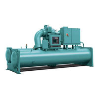
York YK Style H Operation Manual (206 pages)
WITH OPTIVIEW CONTROL CENTER CENTRIFUGAL LIQUID CHILLERS, FOR ELECTRO-MECHANICAL STARTER, SOLID STATE STARTER AND VARIABLE SPEED DRIVE
Brand:
York
| Category:
Chiller
| Size: 6.67 MB
Table of Contents
Table of Contents
5
FIGURE 1 - Model YK Chiller
9
Capacity Control
10
Section 1 - Description of System and Fundamentals of Operation
9
System Operation Description
9
FIGURE 2 - Compressor Pre-Rotation Vanes
10
FIGURE 3 - Refrigerant Flow-Thru Chiller
11
Section 2 - Optiview Control Center Introduction
13
FIGURE 4 - Optiview Control Center
15
TABLE 1 - Addresses and Associated Data
19
Home Screen
21
Optiview Control Center
15
Display Only
16
Interface Conventions Overview
16
Programmable
16
Safety Stop
16
Navigation
17
FIGURE 5 - Home Screen
21
FIGURE 6 - Home Screen with Stop Button
23
FIGURE 7 - System Screen
25
Displays the Temperature of the Liquid as It Enters the Condenser
26
Evaporator Screen
27
FIGURE 8 - Evaporator Screen
27
Condenser Screen
31
FIGURE 9 - Condenser Screen
31
FIGURE 10 - Heat Recovery/Head Pressure Control Screen
35
Heat Recovery/Head Pressure Control Screen
35
FIGURE 11 - Head Pressure Control Screen
39
Head Pressure Control Screen
39
FIGURE 12 - Heat Pump Screen
41
Heat Pump Screen
41
FIGURE 13 - Refrigerant Level Control Screen
45
Refrigerant Level Control Screen
45
Compressor Screen
47
FIGURE 14 - Compressor Screen (Screen Shown Is a Unit with Proximity Probe)
47
Capacity Control Screen
51
FIGURE 15 - Capacity Control Screen
51
Capacity Control Setpoints Screen
55
FIGURE 16 - Capacity Control Setpoints Screen (Screen Shown Is Heating/Cooling Unit with Raptyr VSD)
55
TABLE 2 - Capacity Control Setpoint Programmable Settings
56
FIGURE 17 - Anti Surge Screen (PRV Capacity Control Screen Shown)
57
Capacity Control Override Turning Screen
59
FIGURE 18 - Capacity Control Override Turning Screen
59
FIGURE 19 - Proximity Probe Calibration Screen
61
Proximity Probe Calibration Screen
61
FIGURE 20 - Hot Gas Bypass Screen
63
Hot Gas Bypass Screen
63
FIGURE 21 - Surge Protection Screen
65
Surge Protection Screen
65
FIGURE 22 - Variable Geometry Diffuser Screen
69
Variable Geometry Diffuser Screen
69
FIGURE 23 - Variable Geometry Diffuser Setpoints Screen
71
Variable Geometry Diffuser Setpoints Screen
71
FIGURE 24 - Variable Geometry Diffuser Calibration Screen
73
Variable Geometry Diffuser Calibration Screen
73
FIGURE 25 - Pre-Rotation Vanes Calibration Screen
75
Pre-Rotation Vanes Calibration Screen
75
FIGURE 26 - VSD Tuning Screen
77
VSD Tuning Screen
77
FIGURE 27 - Oil Sump Screen
79
Oil Sump Screen
79
Electro-Mechanical Starter Screen
83
FIGURE 28 - Electro-Mechanical Starter Screen
83
FIGURE 29 - Mod "B" Solid State Starter Screen
85
Mod "B" Solid State Starter Screen
85
FIGURE 29 - Mod “B” Solid State Starter Screen
87
FIGURE 30 - Medium Voltage Solid State Starter Screen
87
Medium Voltage Solid State Starter Screen
87
FIGURE 31 - Vyper/Mod D Variable Speed Drive Screen
89
Vyper/Mod D Variable Speed Drive Screen
89
FIGURE 32 - Raptyr Variable Speed Drive Screen
91
Raptyr Variable Speed Drive Screen
91
FIGURE 33 - Medium Voltage Variable Speed Drive Screen
93
Medium Voltage Variable Speed Drive Screen
93
TABLE 3 - Voltage (V)
94
Adaptive Capacity Control Details Screen
97
FIGURE 34 - Adaptive Capacity Control Details Screen
97
FIGURE 35 - Surge Map Screen - Table View
101
Surge Map Screen - Table View
101
FIGURE 36 - Surge Map Screen - List View
103
Surge Map Screen - List View
103
FIGURE 37 - Harmonic Filter Details Screen (Style D VSD and VSD with Part Number 371-03789-XXX (503Hp 60Hz; 419Hp 50Hz)
105
Harmonic Filter Details Screen
105
FIGURE 38 - Motor Lubrication Screen
107
Motor Lubrication Screen
107
FIGURE 39 - Motor Details Screen
111
Motor Details Screen
111
FIGURE 40 - Motor Setpoints Screen
115
Motor Setpoints Screen
115
FIGURE 41 - Setpoints Screen
119
Setpoints Screen
119
FIGURE 42 - Setup Screen
123
Setup Screen
123
FIGURE 43 - Quick Start Screen
127
Quick Start Screen
127
FIGURE 44 - Schedule Screen
131
Schedule Screen
131
FIGURE 45 - User Screen
133
User Screen
133
COMMS Screen
135
FIGURE 46 - COMMS Screen
135
FIGURE 47 - Printer Screen
137
Printer Screen
137
FIGURE 48 - Sales Order Screen
139
Sales Order Screen
139
FIGURE 49 - Operations Screen
141
Operations Screen
141
FIGURE 50 - History Screen
143
History Screen
143
FIGURE 51 - History Details Screen
145
History Details Screen
145
FIGURE 52 - Security Log Screen
147
Security Log Screen
147
FIGURE 53 - Security Log Details Screen
149
Security Log Details Screen
149
Custom View Screen
151
FIGURE 54 - Custom View Screen
151
Custom View Setup Screen
153
FIGURE 55 - Custom View Setup Screen
153
FIGURE 56 - Trend Screen
155
Trend Screen
155
FIGURE 57 - Trend Setup Screen
157
Trend Setup Screen
157
Advanced Trend Setup Screen
159
FIGURE 58 - Advanced Trend Setup Screen
159
Common Slots Screen
161
Anti-Surge Turning Screen
57
System Screen
25
FIGURE 59 - Common Slots Screen
161
TABLE 4 - Master Slot Numbers List for Use with Trend Feature
162
Section 3 - Display Messages
165
Status Messages
165
Run Messages
166
Start Inhibit Messages
167
Warning Messages
167
Cycling Shutdown Messages
170
Routine Shutdown Messages
170
Mod "B" Solid State Starter Cycling Shutdown Messages
173
Compressor Motor Variable Speed Drive: Cycling Shutdown Messages
174
Safety Shutdown Messages
179
Mod "B" Solid State Starter Safety Shutdown Messages
185
Compressor Motor Variable Speed Drive: Safety Shutdown Messages
186
FIGURE 60 - Printer
189
Acceptable Printers
190
Printer Connections
190
Section 4 - Printing
189
Printing Overview
189
Table 5 - Okidata Okipos 441
190
Control Center Setup
191
Downloading System Prints to Alaptop
191
Printer Setup
191
Printer Connections
193
FIGURE 62 - Communications Block Diagram
193
FIGURE 61 - Breckman Printer
193
TABLE 6 - Brecknell CP130
193
FIGURE 63 - Sample Printout (Status)
194
FIGURE 64 - Sample Printout (Setpoints)
196
FIGURE 65 - Sample Printout (Schedule)
198
FIGURE 66 - Sample Printout (Sales Order)
198
FIGURE 67 - Sample Printout (History)
200
FIGURE 68 - Sample Printout (Security Log Report)
202
FIGURE 69 - Sample Printout (Trend Data New or Existing Points)
202
FIGURE 70 - Sample Printout (Custom Screen Report)
202
FIGURE 71 - Sample Printout (Adaptive Capacity Control New Map Point Report)
203
FIGURE 72 - Sample Printout (Adaptive Capacity Control Existing Map Points Report)
203
TABLE 7 - si Metric Conversion
205
Advertisement
York YK Style H Operation Manual (212 pages)
Centrifugal Liquid Chillers with OptiView Control Center
Brand:
York
| Category:
Chiller
| Size: 9.28 MB
Table of Contents
Table of Contents
3
General Safety Guidelines
7
Safety Symbols
7
YORK Chiller Access Manager - System Security Statement
8
Changeability of this Document
9
Associated Literature
10
Conditioned Based Maintenance
10
Nomenclature
11
Description of System and Fundamentals of Operation
12
System Operation Description
12
Capacity Control
13
Optiview™ Control Center Introduction
15
Optiview™ Control Center
16
Safety Stop
17
Interface Conventions Overview
18
Display Only
18
Programmable
18
Navigation
26
Optiview Screens
28
Home Screen
28
Home Screen with Stop Button
30
System Screen
31
Evaporator Screen
33
Condenser Screen
36
Heat Recovery/Head Pressure Control Screen
39
Head Pressure Control Screen
43
Heat Pump Screen
45
Refrigerant Level Control Screen
48
Compressor Screen
50
Capacity Control Screen
52
Capacity Control Setpoints Screen
55
Anti-Surge Turning Screen
57
Capacity Control Override Tuning Screen
58
Proximity Probe Calibration Screen
59
Hot Gas Bypass Screen
61
Surge Protection Screen
63
Variable Geometry Diffuser Screen
67
Variable Geometry Diffuser Setpoints Screen
69
Variable Geometry Diffuser Calibration Screen
71
Pre-Rotation Vanes Calibration Screen
73
VSD Tuning Screen
75
Oil Sump Screen
77
Electromechanical Starter Screen
80
Mod B Solid State Starter Screen
82
Medium Voltage Solid State Starter Screen
84
Hyp/Mod D Variable Speed Drive Screen
86
Variable Speed Drive Screen
88
Medium Voltage Variable Speed Drive Screen
90
Adaptive Capacity Control Details Screen
93
Surge Map Screen - Table View
95
Surge Map Screen - List View
97
Harmonic Filter Details Screen
99
Motor Lubrication Screen
101
Motor Details Screen
104
Motor Setpoints Screen
110
Setpoints Screen
114
Remote Control
116
Setup Screen
118
Diagnostics Screen
121
Maintenance Screen
123
Serial/Sd Screen
125
Quick Start Screen
127
Schedule Screen
131
User Screen
133
Comms Screen
135
Printer Screen
137
Sales Order Screen
139
Operations Screen
141
History Screen
143
History Details Screen
145
Security Log Screen
147
Security Log Details Screen
149
Custom View Screen
150
Custom View Setup Screen
151
Trend Screen
153
Trend Setup Screen
155
Advanced Trend Setup Screen
158
Common Slots Screen
160
Master Slot Numbers List
162
Display Messages
165
Status Messages
165
Run Messages
166
Start Inhibit Messages
167
Warning Messages
168
Routine Shutdown Messages
172
Cycling Shutdown Messages
172
Mod B Solid State Starter Cycling Shutdown Messages
175
Compressor Motor Variable Speed Drive: Cycling Shutdown Messages
177
Safety Shutdown Messages
184
Mod B Solid State Starter Safety Shutdown Messages
191
Compressor Motor Variable Speed Drive: Safety Shutdown Messages
192
Printing
195
Printing Overview
195
Acceptable Printers
196
Printer Setup
197
Control Center Setup
198
Downloading System Prints to a Laptop
198
Sample Printouts
201
Unit Conversion
212
Advertisement
Related Products
York Millennium YK M3 M3 G4 THRU YK S6 S4 J2
York Millennium YK S6 S4 J2
York YK Series
York YK
York CodePak YK L1 L1 G4
York CodePak YK S2 S2 J4
York YK-EP B
York YK-EP
York YGWH 260
York YCAV0357P
York Categories
Air Conditioner
Heat Pump
Chiller
Furnace
Air Handlers
More York Manuals
Login
Sign In
OR
Sign in with Facebook
Sign in with Google
Upload manual
Upload from disk
Upload from URL