Sign In
Upload
Manuals
Brands
York Manuals
Chiller
YHAU-CE-JE Series
York YHAU-CE-JE Series Chiller-Heater Manuals
Manuals and User Guides for York YHAU-CE-JE Series Chiller-Heater. We have
1
York YHAU-CE-JE Series Chiller-Heater manual available for free PDF download: Installation Operation & Maintenance
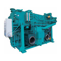
York YHAU-CE-JE Series Installation Operation & Maintenance (136 pages)
DOUBLE-EFFECT EXHAUST GAS ABSORPTION CHILLER-HEATER
Brand:
York
| Category:
Chiller
| Size: 8 MB
Table of Contents
Table of Contents
5
Section 1 - General Chiller-Heater and Safety Information
11
About this Manual
11
Introduction
11
Warranty
11
High Temperature and Pressure Cleaning
12
Quality Assurance
12
Safety Labels
12
FIGURE 1 - YHAU-CE-JE Components
15
How It Works (Exhaust Gas Units)
16
Section 2 - Product Description
15
Chiller-Heater Components
15
Control Panel
15
FIGURE 2 - Two Step Exhaust Gas Absorption Chiller-Heater Cycle Diagram (Cooling Mode)
16
FIGURE 3 - Warning
23
Indoor and Outdoor Installation
24
Inspection
24
Inspection Window
24
Installation Guidelines
24
Structural Support and Installation
24
Electrical
25
Precautions for Use
25
Electrical Shock Cautions
26
Exhaust Gas Damper
26
Exhaust Gas Temperature Sensor
26
Leak Testing
26
Use of Gas
26
Vibration and Isolation Details
27
Absorber
17
Evaporator
17
Plate Type Heat Exchangers
18
Two-Step Evaporator - Absorber
18
High Temperature Generator (HTG)
19
Parallel Flow
19
Condenser
20
Crystallization
20
Waste Hot Water-Driven Generator and Low Temperature Generator
20
Why Does Crystallization Occur
21
Section 3 - Handling, Storage, Installation and Reassembly
23
FIGURE 4 - Vibration and Isolation Details
27
FIGURE 5 - Nozzle Locations (Example - One Exhaust Gas Outlet Flange)
28
FIGURE 6 - Nozzle Locations (Example - Two Exhaust Gas Outlet Flanges)
29
Hot Insulation and Cold Insulation Procedure
30
TABLE 1 - Insulating Material and Thickness
30
TABLE 2 - Points Requiring Hot or Cold Insulation
30
FIGURE 7 - Hot and Cold Insulation (Example - One Exhaust Gas Outlet Flange)
31
FIGURE 8 - Hot and Cold Insulation (Example - Two Exhaust Gas Outlet Flanges)
31
FIGURE 9 - Exterior of Control Panel
32
Section 4 - Technical Data
33
TABLE 3 - Typical Operational Range
33
FIGURE 10 - External Connection Terminal Details
37
FIGURE 11 - 3 Phase 4 Wire Power Supply Wiring
38
TABLE 4 - Contact Specifications
38
FIGURE 12 - Signal Terminal Transition Wiring
39
FIGURE 13 - Upper Communication System Configuration
40
Connection Port for Ethernet Communication
41
Scope of Delivery
41
TABLE 5 - Scope of Delivery
41
TABLE 6 - Ethernet Interface Specification
41
Communication Data
42
Communication Specification
42
TABLE 8 - Read Command
42
TABLE 7 - Communication Specifications
42
TABLE 9 - Write Command
43
FIGURE 14 - Connection Detail for D-Sub 9Pin
44
TABLE 10 - Scope of Delivery of Upper Communication System
44
User-Created
44
2-Wire Cable Diagrams Without Adaptor
45
TABLE 11 - Cable Diagram (RS-422 or RS485)
45
FIGURE 15 - 2-Wire 1:1 Connection with User-Created Cable
45
FIGURE 16 - 2-Wire N:1 Connection with User-Created Cable
46
FIGURE 17 - 4-Wire 1:1 Connection with User-Created Cable
46
Wire Type Cable Diagrams Without Adaptor
46
Upper Communication Specification
40
Upper Communication System Configuration
40
TABLE 12 - Communication Specifications
47
FIGURE 18 - 4-Wire N:1 Connection with User-Created Cable
47
FIGURE 19 - Sample Sound Testing
48
Section 5 - Commissioning
49
General Guidelines for Use
49
Before Operation
49
TABLE 13 - Rotary Pump Rotation
49
TABLE 14 - Liquid Level Gauges (Sight Glass)
50
Interlock Procedure
51
Start the Chiller-Heater
51
Stop the Chiller-Heater
51
Chilled / Hot Water Outlet Temperature Controller
50
Liquid Level Gauges
50
Precautions for the Use of Water
50
FIGURE 20 - Cooling Start Diagram
52
FIGURE 21 - Cooling Stop Diagram
54
FIGURE 22 - Exhaust Gas Input Preparation Flow Diagram
55
FIGURE 23 - Exhaust Gas Input Stop Preparation Flow Diagram
56
FIGURE 24 - Sequential Operation Flowchart
57
FIGURE 25 - Shutdown Exhaust Gas Chiller-Heater Flowchart
57
Section 6 - Operation
67
Common Items
67
YHAU-CE-JE Control Center
67
Change Numeric Values
68
Date and Time
68
FIGURE 26 - Main Screen
71
Operating Status
71
FIGURE 27 - Data Screen
73
FIGURE 28 - Alarm History Screen
75
FIGURE 29 - Trend Screen
76
FIGURE 31 - Failure Screen
78
FIGURE 32 - Alarm Screen
83
TABLE 16 - Alarm List
84
Control Parameter
86
FIGURE 33 - Setting Screen
86
Operation Switch
87
Select Language
87
TABLE 17 - Solenoid Valves
89
Checks after Operation Starts
90
Purge Procedure
90
Start the Chiller-Heater after It Has Been Stopped for a Long Period
90
Performance Check Method of Vacuum Pump
91
TABLE 15 - Failure List
79
Alarm
83
FIGURE 30 - Trend Screen, Part 2
77
Failure
78
Section 7 - Maintenance
89
Air Purge Valves and Drain Valves
89
Exhaust Duct Inspection
89
Pump Shut off Valves
89
Purge Valves
89
Solenoid Valves
89
Valve Inspection
89
FIGURE 34 - Location of Manual Valve in Purging System (Example)
92
Automatic Method to Purge Non-Condensable Gas from Purging Tank
93
Manual Method to Purge Non-Condensable Gas Directly from Absorber
93
Manual Method to Purge Non-Condensable Gas from Purging Tank
93
TABLE 18 - Purge Valve Operation
94
FIGURE 35 - Purge System
95
FIGURE 36 - Process and Instrumentation Diagram - Cooling Only
96
TABLE 19 - Maintenance and Inspection
99
Operation Mode Selection
102
Purge Manual Start and Stop
102
Refrigerant Pump Manual Stop
102
Blower Fan Manual Stop
103
Waste Hot Water Forced Bypass Manual Operation
103
Exhaust Gas Chimney Requirements
104
Exhaust Gas Contaminants
104
TABLE 20 - Exhaust Gas Contaminants
104
Lifespan of Common Parts
105
TABLE 21 - Lifespan of Common Parts
105
FIGURE 37 - Chilled / Hot Water, Cooling Water, Waste Hot Water, and Waste Exhaust Gas System (Example)
106
TABLE 22 - Tendency of Generation of Scales and Corrosion by Quality of Cooling Water
109
TABLE 23 - Chilled / Hot and Cooling Water Quality Control (Maximum Concentrations)
110
Storage Method of the Chiller-Heater
111
Wet Storage Method
111
Dry Storage Method
112
Precautions against External Damage
112
TABLE 24 - Wet Storage Method
112
Storage Method of the Cooling Water During Heating Operation Period
113
TABLE 25 - Dry Storage Method
113
Wet Storage
113
FIGURE 39 - Wet Storage During Heating Period
114
Work Procedure
114
Dry Storage
115
FIGURE 40 - Dry Storage During Heating Period
115
Work Procedure
115
FIGURE 38 - Chilled / Hot Water, Cooling Water, Waste Hot Water, and Waste Exhaust Gas System (Example)
107
Water Quality Control
107
Chemical Treatment
108
Chemical Water Treatment
108
Flow Speed in Tubes
108
Replacement of Water
108
Treatment for Long Stoppage of the Absorption Chiller-Heater
108
Manual Refrigerant Blowdown and Dilution Method
97
Refrigerant Refining Method
97
Decrystallization Method
98
Indications of Crystallization
98
Decrystallization
98
Maintenance Items
99
Precautions for Decrystallization
99
FIGURE 41 - Duhring Diagram PTX Chart (°F)
116
FIGURE 42 - Duhring Diagram PTX Chart (°C)
117
FIGURE 43 - Specific Gravity - Concentration (°F)
118
FIGURE 44 - Specific Gravity - Concentration (°C)
119
TABLE 26 - Troubleshooting the High Temperature Generator
121
Section 8 - Troubleshooting
121
TABLE 29 - Pumps Overloaded or Overheated
122
TABLE 30 - Troubleshooting Performance Issues
123
Abnormal Solution and Refrigerant Levels
124
Vacuum Pump
124
TABLE 28 - Chilled / Hot Water Suspension
122
TABLE 27 - Refrigerant Overcooled
122
Troubleshooting Performance Issues
123
TABLE 31 - Vacuum Pump Troubleshooting
124
TABLE 32 - Interlock Troubleshooting
125
TABLE 33 - Pump Troubleshooting
125
TABLE 34 - Chilled Water Overcooling Troubleshooting
126
TABLE 35 - Communication Errors
127
TABLE 36 - Other Failure Troubleshooting
128
TABLE 37 - Damper Failure Troubleshooting
129
FIGURE 45 - Troubleshooting Sequence Flow Chart
130
Actions to Take against Power Failure
131
FIGURE 46 - Actions to Take against Power Failure
131
Section 9 - Decommissioning, Dismantling, and Disposal
133
Advertisement
Advertisement
Related Products
York YHAU-CL-130EXE
York YHAU-CH-80EXE
York YHAU-CH-900EXW2S
York YHAU-CGN-240EXS
York YHAU-CGH-240EXS
York YHAU-CGH-360EXS
York YHAU-CGH-800EXS
York YHAU-CGN-1600EXW3H
York YHAU-CGN-1300EXW3H
York YHAU-CGN-180EXH
York Categories
Air Conditioner
Heat Pump
Chiller
Furnace
Air Handlers
More York Manuals
Login
Sign In
OR
Sign in with Facebook
Sign in with Google
Upload manual
Upload from disk
Upload from URL