Sign In
Upload
Manuals
Brands
York Manuals
Chiller
YCRS0140SC
York YCRS0140SC Manuals
Manuals and User Guides for York YCRS0140SC. We have
1
York YCRS0140SC manual available for free PDF download: Installation, Operation And Maintenance Manual
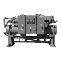
York YCRS0140SC Installation, Operation And Maintenance Manual (104 pages)
WATER COOLED REMOTE CONDENSER 81 TONS THROUGH 194 TONS (285 KW THROUGH 682 KW)
Brand:
York
| Category:
Chiller
| Size: 2.22 MB
Table of Contents
Table of Contents
3
Section 1 General Chiller Information & Safety
6
Introduction
6
Warranty
6
Safety
6
Standards for Safety
6
Responsibility for Safety
7
About this Manual
7
Misuse of Equipment
7
Suitability for Application
7
Structural Support
7
Mechanical Strength
7
General Access
7
Pressure Systems
7
Electrical
7
Refrigerants and Oils
8
High Temperature and Pressure Cleaning
8
Emergency Shutdown
8
Section 2 Product Description
9
Introduction
9
Compressor
9
Motor Starting
10
Capacity Control
10
Oil Separator
11
Oil Cooler
11
Refrigerant Circuits
11
Condenser
11
Cooler
11
Power and Control Panels
12
Microprocessor Controls
12
Motor Current Protection
12
Motor Protector Module
13
Current Overload
13
Thermal Overload
13
Current Unbalance / Loss of Phase
13
Improper Phase Sequence
13
Keypad Controls
13
Status Key
13
Display Keys
14
Print Keys
14
Entry Keys
14
Setpoints Keys
14
Clock Keys
14
Program Key
14
Accessories and Options
14
Alternative Refrigerants
14
Electrical Options
14
Accessories
15
Aternative Chilled Fluid Applications
15
Nomenclature
16
Functional Description
16
Delivery and Storage
17
Inspection
17
Moving the Unit
17
Lifting by Crane / Hoist
17
Lifting by Fork Lift
18
Control Panel Removal
18
Lifting Weights
18
Section 4 Installation
19
Location Requirements
19
Installation of Vibration Isolators
19
Pipework Connection
19
General Requirements
19
Water Treatment
20
Glycol Solutions
20
Pipework Arrangement
21
Recommendations of the Building Services Research Association
21
Connection Types & Sizes
21
Cooler Connections
21
Option Flanges
22
Refrigerant Relief Valve Piping
22
Condenser Cooling Liquid Systems
22
Condenser Piping
22
Discharge Lines
22
Liquid Lines
22
Electrical Connection
24
Power Wiring
24
Units with Single-Point Power Supply Wiring
24
Units with Multi-Point Power Supply Wiring
24
Control Transformer Primary Voltage Tappings
25
Remote Emergency Stop Device
25
Common Input Section Wiring
25
Chilled Liquid Pump
25
Common Run Signal
25
System Alarm
25
Control Panel Wiring
25
Flow Switch
25
Remote Run/Stop
26
Remote Print (PNT)
26
Remote Setpoint Offset - Temperature
26
Remote Setpoint Offset - Current
26
Customer Wiring Data
27
Connection Diagram Legend and Notes
28
Commissioning
29
Preparation
29
Preparation - Power off
29
First Time Start-Up
31
Section 6 Unit Operation
32
Unit Operation
32
General Description
32
Start-Up
32
Normal Running and Cycling
32
Shutdown
32
1 Introduction and Descriptions
33
Input / Output Expansion Board
33
Internal Clock & Memory Backup Battery
33
Power Supply Board
33
Relay Output Board
33
Section 7 Micropanel
33
System Switches 1-2
33
Circuit Breakers
34
Current Transformers (Ct)
34
Logic Section
34
Motor Protector Modules
34
Transformers
34
Remote Current Reset
35
Remote Start/Stop
35
Remote Setpoint Reset
36
Alarm Contacts
37
Anti-Recycle Timer
37
Chilled Liquid Pump Contact
37
Common Input Power Section Voltage Free Contacts
37
Control Panel
37
Remote Emergency Stop Device
37
Run Contact
37
Anti-Coincidence Timer
38
Compressor Heater Control
38
Lead/Lag Compressor Selection
38
Pumpdown (LLSV) Control
38
2 Control Panel Programming and Data Access
39
Display and Status Keys
39
Program and Setup Keys
39
3 Status Keys
40
General
40
General Status Messages
40
Unit Warnings
41
Anticipation Control Status Messages
42
Unit Fault Status Messages
43
System Fault Status Messages
44
Printout on Fault Shutdown
47
4 Display Keys
48
General
48
Chilled Liquid Temps Key
48
System Data Keys
48
Ambient Temp Key
49
Motor Current Key
49
Operating Hrs / Start Counter Key
50
Options Key and Dip Switch Settings
50
DIP Switch Settings
51
Function Key
51
5 Print Keys
52
General
52
Oper Data Key
52
Oper Data - Local Display Messages
52
Oper Data - Remote Printout
54
History Key
55
History - Local Display Messages
55
History - Remote Printout
58
Local Printer Option
59
6 Entry Keys
61
General
61
Numerical Keypad
61
Enter Key
61
Cancel Key
61
Keys
61
7 Setpoint Keys and Chilled Liquid Control
62
General
62
Chilled Liquid Temperature Control
62
Slide Valve Control
63
Load Timers
63
Slide Valve Position
63
Compressor Starting and Loading Sequence
63
Compressor Loading
64
Loading Limiting
64
Compressor Unloading and Shutdown Sequence
64
Local Cooling Setpoints Key
64
Remote Cooling Setpoints Key
65
8 Clock Keys
66
General
66
Set Time/Date Key
66
Set Schedule/Holiday Key
67
Manual Override Key
68
9 Program Keys
69
General
69
User Programmable Values
69
Input/Output Display Routine
72
10 Ems / Bas Interface Card Kits
74
EMS / BAS Remote Temperature Reset
74
Reset Option
74
Section 8 Maintenance
76
General Requirements
76
Daily Maintenance
76
Scheduled Maintenance
76
Standard Units
77
Troubleshooting Guide
78
Sensor Calibration Charts
80
Typical Control Panel Wiring
82
Section 9 Technical Data
84
Flow Rate and Pressure Drop Graphs
84
Physical Data / Sound Data
87
Electrical Data
88
Dimensions
94
Isolator Selection Data
98
Isolator Details
99
Sound Data
100
Compressors
101
Section 10 Spare Parts
102
Recommended Spare Parts
102
Recommended Compressor Oils
102
Associated Drawings
102
Section 11 Decommissioning, Dismantling and Disposal
103
General
103
Advertisement
Advertisement
Related Products
York YCRS0100SC
York YCRS0120SC
York YCRS0180SC
York YCRS0200SC
York YCRS0220SC
York YCRS0240SC
York YCRS Series
York YCRJ77K00
York YCRJ88M00
York YCRJ66H00
York Categories
Air Conditioner
Heat Pump
Chiller
Furnace
Air Handlers
More York Manuals
Login
Sign In
OR
Sign in with Facebook
Sign in with Google
Upload manual
Upload from disk
Upload from URL