Sign In
Upload
Manuals
Brands
YOKOGAWA Manuals
Measuring Instruments
WT210
YOKOGAWA WT210 Manuals
Manuals and User Guides for YOKOGAWA WT210. We have
1
YOKOGAWA WT210 manual available for free PDF download: User Manual
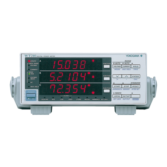
YOKOGAWA WT210 User Manual (316 pages)
Digital Power Meter
Brand:
YOKOGAWA
| Category:
Measuring Instruments
| Size: 5.52 MB
Table of Contents
Product Registration
2
Functional Comparison of the WT210/WT230 and WT200/WT110E/WT130
4
Safety Precautions
8
Startup Guide
17
Wiring the Circuit
18
(Wiring a Three-Phase, Three-Wire System)
22
Installing the WT230
19
Connecting the WT230 Power Supply
20
Turning on the Power to the WT230
20
(Wiring a Single-Phase, Two-Wire System)
21
Wiring the Circuit on the Primary Side of the Inverter
21
Checking the Contents of the Package
5
Standard Accessories
6
Structure of the Manual
10
Conventions Used in this Manual
11
Table of Contents
13
Functions
18
Wiring the Circuit on the Secondary Side of the Inverter
22
Selecting the Wiring System
24
Selecting the Measurement Range
25
Selecting the Voltage Range
25
Selecting the Current Range
26
Turning on the Power to the Circuit under Measurement
27
Displaying Voltage, Current, and Active Power
28
Displaying the Voltage on the Primary Side of the Inverter on Display a
28
Displaying the Current on the Primary Side of the Inverter on Display B
29
Displaying the Active Power on the Primary Side of the Inverter on Display C
30
Displaying the Voltage of the Secondary Side of the Inverter on Display a
31
Displaying the Current on the Secondary Side of the Inverter on Display B
32
Displaying the Active Power on the Secondary Side of the Inverter on Display C
33
Displaying the Efficiency
34
Setting the Efficiency Computation
34
Displaying the Efficiency
35
Confirming the Displayed Efficiency
37
System Configuration and Block Diagram
38
Functions
40
Digital Numbers and Characters and Initial Menus
43
Front Panel, Rear Panel, and Top View
46
Operation Keys and Functions/Element Display
47
Auto Range Monitor, Overrange, and Error Displays During Measurement
49
Handling Precautions
50
Installing the Instrument
51
Wiring Precautions
53
For Making Accurate Measurements
56
Connecting the Power Supply
57
Turning ON/OFF the Power Switch and Opening Message
58
Directly Wiring the Circuit under Measurement
60
Using an External PT or CT to Wire the Circuit under Measurement
62
Using an External Sensor to Wire the Circuit under Measurement
64
Selecting the Wiring System (Applies Only to the WT230)
68
Selecting the Measurement Mode
69
Selecting the Measurement Synchronization Source
71
Turning ON/OFF the Input Filter
73
Selecting the Measurement Range When Using Direct Input
75
Setting the Scaling Value When External PT/CT Is Used
79
Selecting the Measurement Range and Setting the Scaling Constant When External Sensor Is Used (Option)
82
Using the Averaging Function
85
Using the MAX Hold Function
88
Computing the Efficiency (Applies to WT230 Only)
89
Computing the Crest Factor
91
Performing Four Arithmetical Operation
93
Computing the Average Active Power During Integration
97
Selecting the Number of Displayed Digits and the Display Update Rate
99
Selecting the Crest Factor
101
Chapter 1 Functional Overview and Digital Display
38
Chapter 2 Names and Functions of Parts and Auto Range Monitor, Overrange
46
Chapter 3 Before Starting Measurements
50
Chapter 4 Setting Measurement Conditions and Measurement Range
69
Chapter 5 Displaying Measurement Results and Computation Results
103
Displaying Voltage, Current and Active Power
103
Displaying Apparent Power, Reactive Power and Power Factor
105
Displaying the Phase Angle
106
Displaying the Frequency
107
Displaying Efficiency (WT230 Only), Crest Factor, Four Arithmetic Operation Value, Average Active Power, and Peak Value
109
Integration
110
Chapter 6 Integration
111
Integrator Functions
111
Setting Integration Mode and Integration Timer
114
Displaying Integrated Values
116
Precautions Regarding Use of Integrator Function
119
Chapter 7 Harmonic Measurement Function (Option)
122
Chapter 8 Store/Recall Function of Measured/Computed Data and Setup
131
Chapter 9 External In/Output Function
137
Chapter 10 GP-IB Interface (Option)
161
Chapter 11 Serial Interface (Option)
178
Serial Interface Functions and Specifications
178
GP-IB Interface Functions and Specifications
161
Responses to Interface Messages, and Remote/Local Modes
163
Status Byte Format (before the IEEE 488.2 Standard)
164
Output Format for Measured/Computed Data, Setup Parameters, and Error Codes
165
Setting the Address and Mode
171
Setting the Output Items
173
Commands (before the IEEE 488.2 Standard)
176
Pin Arrangement and Pin Assignments of the External I/O Connector (Option)
137
Remote Control (Option)
139
D/A Output (Option)
140
Comparator Function (Option)
145
Setting the Comparator Mode (Option)
148
Setting the Comparator Limit Values (Option)
149
Comparator Display (Option)
153
Turning the Comparator Function ON/OFF (Option)
155
Outputting to an External Plotter or External Printer
156
Storing/Recalling Measured/Computed Data
131
Storing/Recalling Setup Parameters
135
Setting the Target Element, PLL Source and Harmonic Distortion Method
125
Turning ON/OFF the Harmonic Measurement Function
127
Setting the Harmonic Order and Displaying the Measured Harmonic Value
128
Serial Interface Specifications
179
Connecting the Interface Cable
180
Setting the Mode, Handshaking Method, Data Format and Baud Rate
182
Format and Commands of Output Data (before the IEEE488.2 Standard)
185
Back-Up of Setup Parameters
186
Initializing Setup Parameters
187
Performing Zero-Level Compensation
189
Key Lock
190
Commands
191
Before Programming
206
Sample Program Image
208
Sample Program (Initialization, Error, and Execution Functions)
209
Sample Program (Output of Normal Measurement Data)
212
Sample Program (Output of Harmonic Measurement Data)
215
Overview of IEEE 488.2-1992
217
Messages
219
Program Format
219
Symbols Used in Syntax Descriptions
219
Commands
221
Data
223
Responses
223
Synchronization with the Controller
225
Command List
227
Commands
227
Aoutput Group
231
Communicate Group
232
Configure Group
234
Display Group
238
Harmonics Group
240
Integrate Group
241
MATH Group
242
Measure Group
244
Recall Group
252
Relay Group
253
Sample Group
255
Status Group
256
Store Group
257
Common Command Group
258
Overview of the Status Report
260
Status Report
260
Status Byte
261
Standard Event Register
262
Extended Event Register
263
Output Queue and Error Queue
264
Before Programming
265
Sample Program Image
266
Sample Program (Initialization, Error, and Execution Functions)
267
Sample Program (Output of Normal Measurement Data)
270
Sample Program (Output of Harmonic Measurement Data)
273
ASCII Character Codes
276
Communication-Related Error Messages
277
Chapter 12 Initializing Setup Parameters, Zero-Level Compensation, and Key
186
Adjustments
279
Chapter 15 Maintenance and Troubleshooting
279
Calibration
284
Specifications
287
In Case of Malfunctioning
291
Error Codes and Corrective Actions
292
Replacing the Fuse
294
Recommended Replacement Parts
295
Chapter 16 Specifications
296
Input
296
Accuracy
298
Functions
300
Comparator Output (/CMP Option)
306
D/A Output (/DA4, /DA12, and /CMP Options)
306
External Sensor Input (/EX1 and /EX2 Options)
306
Remote Control Input/Output Signal (/DA4, /DA12, and /CMP Options)
306
GP-IB Interface (Standard on -C1, /C1 Option)
307
Serial (RS-232-C) Interface (Standard on -C2, /C2 Option)
307
General Specifications
308
Dimensional Drawings
310
Advertisement
Advertisement
Related Products
YOKOGAWA WT230
YOKOGAWA WT200
YOKOGAWA WT500
YOKOGAWA WT310EH
YOKOGAWA WT3001E
YOKOGAWA WT3002E
YOKOGAWA WT1800E
YOKOGAWA WT332
YOKOGAWA WT300
YOKOGAWA WT333E
YOKOGAWA Categories
Measuring Instruments
Test Equipment
Transmitter
Controller
Media Converter
More YOKOGAWA Manuals
Login
Sign In
OR
Sign in with Facebook
Sign in with Google
Upload manual
Upload from disk
Upload from URL