Sign In
Upload
Manuals
Brands
YOKOGAWA Manuals
Measuring Instruments
PH450G
YOKOGAWA PH450G Manuals
Manuals and User Guides for YOKOGAWA PH450G. We have
5
YOKOGAWA PH450G manuals available for free PDF download: User Manual, Technical Information
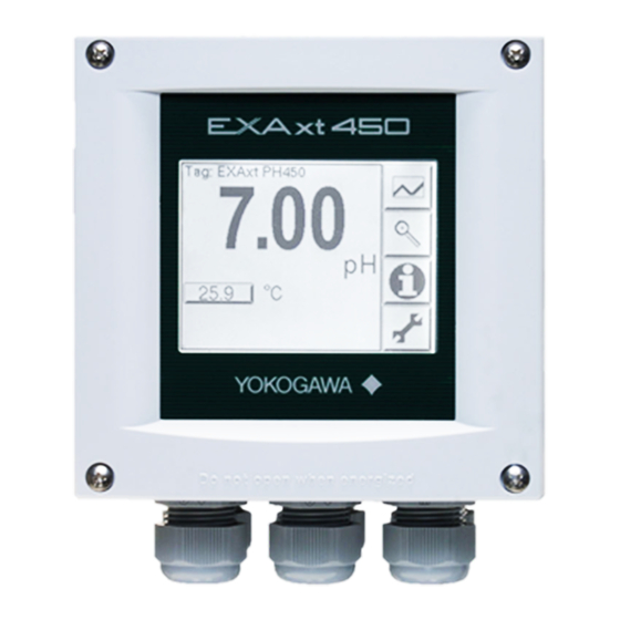
YOKOGAWA PH450G User Manual (88 pages)
pH/ORP
Brand:
YOKOGAWA
| Category:
Media Converter
| Size: 2 MB
Table of Contents
Preface
3
Table of Contents>
3
Warranty and Service
4
Safety Precautions
6
CE Marking Products
8
Table of Contents
9
1 Introduction and General Description
13
Instrument Check
13
Application
14
2 General Specifications
15
3 Installation and Wiring
19
Installation and Dimensions
19
Installation Site
19
Mounting Methods
19
Wiring
22
Preparation
22
Cables, Terminals, Glands and Conduit Adapter
23
Wiring the Power Supply
25
General Precautions
25
Access to Terminal and Cable Entry
26
AC Power
26
DC Power
26
Grounding the Housing
27
Switching on the Instrument
27
Wiring the Contact Signals
28
General Precautions
28
Contact Outputs
28
Contact Input
29
Wiring the Ma-Output Signals
29
General Precautions
29
Analog Output Signals
29
Wiring the Sensor System
29
Sensor Wiring
30
Connection Cable
31
Sensor Cable Connection With Special Grommet (Ph450G-□-A Version)
33
Sensor Cable Connections Using Junction Box (Ba10) And Extension Cable
34
Wf10)
34
4 Operation
37
Main Display Functions
37
Trending Graphics
37
Zoom in on Details
38
Actual Ma1
38
Actual Ma2
38
Zero
39
Slope
39
Sensor MV
39
Reference Impedance
39
Last Calibrated
39
Calibration Due
39
Projected Calibration
40
Projected Replacement
40
Hart ID
40
Software Revision
40
Hart Device Revision
40
Logbook
40
Information Function
41
Setup-Calibration & Commissioning
41
Secondary-Primary Value Display Switch
42
Navigation of the Menu Structure
42
Setup Concentration Mode
43
5 Menu Structure Commissioning
45
Sensor Setup
45
Measurement Setup
46
Temperature Setting
46
Temperature Compensation
46
Calibration Settings
48
Impedance Setting
50
Ma Output Setup
50
Contact Output Setup
54
Fail
58
Simulate
58
Error Configuration Errors 1/3 ~ 3/3
58
Logbook Configuration
60
Advanced Setup
60
Display Setup
62
Main Display
62
6 Calibration
63
Calibration Check with Buffer Solutions
63
Manual Calibration Mode
63
Automatic Calibration Mode
63
Sample Calibration Mode
64
Temperature Calibration
64
ORP & Rh Calibration
65
Operation of Hold Function During Calibration
65
Contact Output Setup
65
7 Maintenance
69
Periodic Maintenance
69
Periodic Maintenance of the Sensor
69
LCD Adjustment
70
Contrast Adjustment
70
8 Troubleshooting
73
Calibration Check
73
Predictive Maintenance
73
Error Displays and Actions
74
Appendixes
75
Appendix 1 Buffer Tables
75
Appendix 2 HART HHT (275/375) Menu Structure
77
Appendix 3 Temperature Compensation Matrix
80
Appendix 4 Control Drawing for FM Approval
82
Appendix 5 ORP Electrode Check
83
Parts List
85
Revision Record
87
Advertisement
YOKOGAWA PH450G User Manual (91 pages)
pH and ORP Converter
Brand:
YOKOGAWA
| Category:
Media Converter
| Size: 4 MB
Table of Contents
Table of Contents
5
1 Introduction and General Description
9
Instrument Check
9
Application
9
2 GENERAL SPECIFICATIONS of Exaxt PH450G
10
3 Installation and Wiring
13
Installation and Dimensions
13
Installation Site
13
Mounting Methods
13
Wiring
15
Preparation
15
Cables, Terminals and Glands
16
Wiring the Power Supply
17
General Precautions
17
Access to Terminal and Cable Entry
18
AC Power
18
DC Power
18
Grounding the Housing
18
Switching on the Instrument
18
Wiring the Contact Signals
19
General Precautions
19
Contact Outputs
19
Contact Intput
19
Wiring the Ma-Output Signals
19
Analog Output Signals
19
Impedance Measurement Jumper Settings
20
Wiring the Sensor System
21
Sensor Wiring
21
Connection Cable
21
Sensor Cable Connection with Special Grommet (450G- □ -A Version)
24
Sensor Cable Connections Using Junction Box (BA10) and Extension Cable (WF10)
25
4 OPERATION of Exaxt PH450G
27
Main Display Functions
27
Trending Graphics
27
Zoom in on Details
27
Actual Ma1
27
Actual Ma2
27
Zero
27
Slope
28
Sensor MV
28
Reference Impedance
28
Last Calibrated
28
Calibration Due
28
Projected Calibration
28
Projected Replacement
28
Serial Number
29
Software Revision
29
HART Device Revision
29
Logbook
29
Information Function
29
Setup-Calibration & Commissioning
29
Secondary-Primary Value Display Switch
29
Navigation of the Menu Structure
30
Setup Concentration Mode
30
5 Menu Structure Commissioning
32
Sensor Setup
32
Measurement Setup
32
Temperature Setting
32
Temperature Compensation
32
Calibration Settings
34
Impedance Setting
34
Ma Output Setup
36
Contact Output Setup
38
Fail
40
Simulate
40
Error Configuration
42
Logbook Configuration
42
Advanced Setup
44
Display Setup
46
6 Calibration
48
Calibration Check with Buffer Solutions
48
Manual Calibration Mode
48
Automatic Calibration Mode
48
Sample Calibration Mode
49
Temperature Calibration
49
ORP & Rh Calibration
49
Operation of Hold Function During Calibration
49
Contact Output Setup
49
7 Maintenance
51
Periodic Maintenance
51
Periodic Maintenance of the Sensor
51
LCD Adjustment
52
8 Troubleshooting
53
General
53
Calibration Check
53
Predictive Maintenance
53
Error Displays and Actions
53
9 Quality Inspection
54
10 Spare Parts
58
Appendices
59
Appendix 1, Buffer Tables
59
Appendix 2, HART HHT (275/375) Menu Structure
60
Appendix 3, Temperature Compensation Matrix
64
Appendix 4, Control Drawing For Fm Approval
65
Revision Record
69
YOKOGAWA PH450G User Manual (53 pages)
Chemical Cleaning pH Measuring System
Brand:
YOKOGAWA
| Category:
Measuring Instruments
| Size: 1 MB
Table of Contents
Introduction
2
Safety Precautions
4
Table of Contents
6
1 General
8
Standard Specifications
8
Model and Suffix Codes
11
External Dimensions
13
2 Installation
16
Installing the PH8SM3 Chemical Cleaning Unit for a Chemical Cleaning System
16
Where to Install the Unit
16
Installation Facilities
17
Installing Chemical Cleaning Unit
17
Installing the PH8HS3 Holder
18
Where to Install the Holder
18
Installation Facilities
18
Installing the PH8HS3 Holder
19
3 Piping and Wiring
22
Piping
22
Line for Connecting Air Source
23
Line for Actuating Cylinder to Drive Sensor Pneumatically (Upward)
23
Line for Actuating Cylinder to Drive Sensor Pneumatically (Downward)
23
Line for Forced Feeding of Chemical Solution and Air-Bubbling
23
Line for Pressurizing Kcl Reserve Tank
23
Wiring
24
Wiring System with 2-Wire Analyzer
27
4 Operation
30
Names and Functions of Components
30
How the Chemical Cleaning Ph Measuring System Works
32
Operating Modes
32
WASH (Cleaning) Command
32
Wash Sequence
33
Startup
34
Inspection of Piping and Wiring
34
Supplying Chemical Solution to Holding Tank
34
Supplying Kcl Solution to Reserve Tank
35
Adjustment of Pneumatic Pressure
35
Setting Duration of Forced Feeding of Chemical Solution and Output of CYLINDER FAIL Signal
36
Supplying Power
36
Entering Data Related to WASH Operation
36
Verifying WASH Operation
37
Calibration with Standard Solution
37
Regular Operation
37
Data Acquisition in Early Stages of Operation
37
Inspections During Regular Operation
38
Behaviour During Power Failure/Restart
38
Operation When Shutting down the System
38
Procedure When Restarting System Operation
39
5 Inspection and Maintenance
40
Inspection and Maintenance of Operating Unit for PH8SM3 Chemical Cleaning System
40
Inspection of Piping (between Chemical Cleaning Chamber and Holder)
40
Inspection of Solenoid Valves
40
Replacement of Fuses in the Power Supply Box
41
Inspection and Maintenance of PH8HS3 Holder
41
Removing Foreign Matter from Wetted Part of Sensor Holder
41
Inspecting Gasket on the Bottom Plate of Cleaning Chamber
41
Cleaning and Lubricating Pneumatic Cylinder for Driving the Sensor Holder
42
Inspecting O-Rings on Sensor Holder
43
Inspecting Terminal Block for Limit Switch
43
6 Troubleshooting
44
More than 100 Ml of Chemical Solution at a Time Is Being Fed to Holder
44
A Smaller Quantity of Chemical Solution Is Fed to Holder
45
CYLINDER FAIL Signal Appears
45
When Liquid Keeps Leaking from Bottom Plate of Cleaning Chamber
45
Chemical Solution Cannot be Fed into Cleaning Chamber
46
Customer Maintenance Parts List (PH8SM3)
48
Advertisement
YOKOGAWA PH450G User Manual (67 pages)
Sampling System
Brand:
YOKOGAWA
| Category:
Samplers
| Size: 3 MB
Table of Contents
Introduction
3
After-Sales Warranty
5
Table of Contents
7
Overview
9
System Confi Guration
9
St401G-Fc4
11
St401G-Ph
11
St401G-Pf
11
Specifications
13
Installation, Piping, and Wiring
15
Unpacking
15
Installation Place
15
Installation
15
Piping
48
Wiring
48
Operation
57
ST401G-FC4-N-A (with Free Available Chlorine Analyzer)
57
ST401G-PH--A (with Ph Converter System)
58
St401G-Pf¨-¨-A
59
St401G-Fc4-N-A/Azc
60
St401G-Pf--A/Azc
61
Converter System)
61
Maintenance
63
Confi Rmation of Fl Ow Rates of Sample
63
Leakage Check
63
Maintenance of each Built-In Equipment
63
Customer Maintenance Parts List
65
Revision Information
66
YOKOGAWA PH450G Technical Information (51 pages)
pH/ORP/Conductivity Converters HART Communication
Brand:
YOKOGAWA
| Category:
Media Converter
| Size: 0 MB
Table of Contents
Table of Contents
1
What Is HART Communication
2
Downloading And Installing DD Files
2
Before Using Fieldmate
2
Installing the DD File
3
Connecting Setup Tool
3
Functions Available Via Hart Communication
3
Operational Precaution
4
Setting on the PH450G/SC450G/ISC450G and a Setup Tool (Communication Tool)
4
Operation With Handling All The Parameters Of The Ph450G/Sc450G/Isc450G
4
DD Online Parameters For Ph450G (Device Revision 2, DD File Revision 2)
4
DD Online Parameters For Sc450G (Device Revision 2, DD File Revision 2)
21
DD Online Parameters for ISC450G (Device Revision 2, DD File Revision 2)
36
Revision Information
51
Advertisement
Related Products
YOKOGAWA PH8SM3
YOKOGAWA PH8EFP
YOKOGAWA PH8HS3
YOKOGAWA PH201G
YOKOGAWA PH71
YOKOGAWA PH72
YOKOGAWA PH72-21-E-AA
YOKOGAWA PH72-13-E-AA
YOKOGAWA PH72SN
YOKOGAWA PH91
YOKOGAWA Categories
Measuring Instruments
Test Equipment
Transmitter
Controller
Media Converter
More YOKOGAWA Manuals
Login
Sign In
OR
Sign in with Facebook
Sign in with Google
Upload manual
Upload from disk
Upload from URL