YOKOGAWA PH450G User Manual
Ph/orp
Hide thumbs
Also See for PH450G:
- User manual (91 pages) ,
- Technical information (51 pages) ,
- User manual (67 pages)

Subscribe to Our Youtube Channel
Related Manuals for YOKOGAWA PH450G


Summary of Contents for YOKOGAWA PH450G
- Page 1 User’s Model PH450G Manual pH/ORP Converter [Style: S2] IM 12B07C05-01E 6th Edition...
- Page 2 NOTE This page may be referred to when reading pages where subsequent submenu screens are shown in the text. Connection to the relevant submenu screen is indicated by a dotted line with an arrow. Note that screens in the text are typical examples and actual screens may differ depending on the set parameters.
-
Page 3: Preface
WARNING Installation and wiring The PH450G converter should only be used with equipment that meets the relevant IEC, American or Canadian standards. Yokogawa accepts no responsibility for the misuse of this unit. CAUTION... -
Page 4: Warranty And Service
• If the product is not used in a manner specified in this manual, the safety of this product may be impaired. Yokogawa is not responsible for damage to the instrument, poor performance of the instrument or losses resulting from such, if the problems are caused by: • Improper operation by the user. • Use of the instrument in improper applications • Use of the instrument in an improper environment or improper utility program... - Page 5 <PREFACE> In the event of warranty claim, the defective goods should be sent (freight paid) to the service department of the relevant sales organization for repair or replacement (at Yokogawa discretion). The following information must be included in the letter accompanying the returned goods: • Part number, model code and serial number • Original purchase order and date • Length of time in service and a description of the process • Description of the fault, and the circumstances of failure • Process/environmental conditions that may be related to the failure of the device. • A statement whether warranty or non-warranty service is requested • Complete shipping and billing instructions for return of material, plus the name and phone number of a contact person who can be reached for further information.
-
Page 6: Safety Precautions
• If this instrument is used in a manner not specified in this user’s manual, the protection provided by this instrument may be impaired. • If any protection or safety circuit is required for the system controlled by the product or for the product itself, prepare it separately. • Be sure to use the spare parts approved by Yokogawa Electric Corporation (hereafter simply referred to as YOKOGAWA) when replacing parts or consumables. • Modification of the product is strictly prohibited. • The following safety symbols are used on the product as well as in this manual. WARNING This symbol indicates that an operator must follow the instructions laid out in this manual in order to avoid the risks, for the human body, of injury, electric shock, or fatalities. - Page 7 • The purpose of these user’s manuals is not to warrant that the product is well suited to any particular purpose but rather to describe the functional details of the product. • No part of the user’s manuals may be transferred or reproduced without prior written consent from YOKOGAWA. • YOKOGAWA reserves the right to make improvements in the user’s manuals and product at any time, without notice or obligation. • If you have any questions, or you find mistakes or omissions in the user’s manuals, please contact our sales representative or your local distributor. Drawing Conventions Some drawings may be partially emphasized, simplified, or omitted, for the convenience of description.
-
Page 8: Ce Marking Products
<PREFACE> CE marking products Authorized Representative in EEA The Authorised Representative for this product in EEA is Yokogawa Europe B.V. (Euroweg 2, 3825 HD Amersfoort, The Netherlands). n Identification Tag This manual and the identification tag attached on packing box are essential parts of the product. Keep them together in a safe place for future reference. Users This product is designed to be used by a person with specialized knowledge. -
Page 9: Table Of Contents
TOC-1 <TABLE OF CONTENTS> Model PH450G pH/ORP Converter [Style: S2] IM 12B07C05-01E 6th Edition CONTENTS PREFACE ....................i Safety Precautions ................. iv CE marking products ................vi 1. INTRODUCTION AND GENERAL DESCRIPTION .......1-1 Instrument check ................1-1 Application ..................1-2 2. GENERAL SPECIFICATIONS ............2-1 3. - Page 10 TOC-2 <TABLE OF CONTENTS> 3.7.2 Sensor cable connection with special grommet (PH450G-□-A version) ...3-15 3.7.3 Sensor cable connections using junction box (BA10) and extension cable (WF10) ....................3-16 4. OPERATION ..................4-1 Main display functions ..............4-1 Trending graphics ..............4-1 Zoom in on details ..............4-2 4.3.1 Actual mA1 ....................4-2 4.3.2 Actual mA2 ....................4-2 4.3.3 Zero ......................4-3 4.3.4 Slope ......................4-3 4.3.5 Sensor mV ....................4-3...
- Page 11 TOC-3 <TABLE OF CONTENTS> 5.11 Error configuration Errors 1/3 ~ 3/3 ..........5-14 5.12 Logbook configuration ..............5-16 5.13 Advanced setup ................5-16 5.14 Display setup ...................5-18 6. CALIBRATION ................6-1 Calibration check with buffer solutions.........6-1 Manual calibration mode ..............6-1 Automatic calibration mode ............6-1 Sample calibration mode ..............6-2 Temperature calibration ..............6-2 ORP &...
- Page 12 Blank Page...
-
Page 13: Introduction And General Description
This manual also includes a basic troubleshooting guide to answer typical user questions. Yokogawa can not be responsible for the performance of the PH450G converter if these instructions are not followed. Instrument check Upon delivery, unpack the instrument carefully and inspect it to ensure that it was not damaged during shipment. -
Page 14: Application
The PH450G is delivered with a general purpose default setting for programmable items (see Chapter 5). While this initial configuration allows easy start-up, the configuration should be adjusted to suit each particular application. An example of an adjustable item is the type of temperature sensor used. The PH450G can be adjusted for a number of different types of temperature sensors. Details provided in this instruction manual are sufficient to operate the PH450G with all Yokogawa sensor systems and a wide range of third-party commercially available probes. -
Page 15: General Specifications
<2. GENERAL SPECIFICATIONS> 2. GENERAL SPECIFICATIONS Input specifications: Dual high impedance input (≥ 10 Ω). Input ranges: -2 to 16 pH ORP; -1500 to 1500 mV 0 to 100 rH Temperature; - Pt1000; -30 to 140ºC - Pt100; -30 to 140ºC - 350Ω (DKK); -30 to 140ºC - 5k1; -30 to 140ºC - 6k8;... - Page 16 Cast Aluminum housing with chemically resistant coating; Polycarbonate cover with Polycarbonate flexible window Protection IP66 / NEMA 4X / CSA Type 3S Colour; Silver grey PH450G-A(D)-A: IP66 cable glands are supplied with the unit PH450G-A(D)-U: N EMA 4X close up plugs are mounted in the unused cable entry holes and can be replaced by conduit fittings as required Pipe, Panel or Wall mounting using optional hardware Optional conduit adapter;...
- Page 17 <2. GENERAL SPECIFICATIONS> Safety, EMC and RoHS conforming standards Safety: EN 61010-1 EN 61010-2-030 EN 61010-2-201 CAN/CSA C22.2 No.61010-1 CAN/CSA C22.2 No.61010-2-030 CAN/CSA IEC 61010-2-201 UL 61010-1 UL 61010-2-030 UL 61010-2-201 EMC: EN 61326-1 Class A, Table 2 EN 61326-2-3 EN 61000-3-2 Class A EN 61000-3-3 RCM: EN61326-1 Class A Korea Electromagnetic Conformity Standard *1: Influence of immunity environment (Criteria A): Output shift is specified within ±35% of F.S. Note: This instrument is a Class A product, and it is designed for use in the industrial environment.
- Page 18 <2. GENERAL SPECIFICATIONS> Model and Suffix Codes [Style: S2] Model Suffix code Option code Description PH450G ---------------- ----------------- pH/ORP Converter Power ----------------- AC version (100…240 VAC) ----------------- DC version (12…24 VDC) Type ----------------- General purpose version ----------------- FM version (*3) Mounting Hardware Universal mounting kit (panel, pipe, wall) Pipe and wall mounting hardware (*2) Panel mounting hardware (*2) Hood Awning hood (stainless steel) (*2) Conduit adapter...
-
Page 19: Installation And Wiring
3. INSTALLATION AND WIRING Installation and dimensions 3.1.1 Installation site The PH450G converter is weatherproof and can be installed inside or outside. It should, however, be installed as close as possible to the sensor to avoid long cable runs between sensor and converter. In any case, the cable length should not exceed 50 metres (162 feet). - Page 20 <3. INSTALLATION AND WIRING> Unit: mm (inch) Hood (Option code: /H5, some cutout on the left side cover) 184(7.2") 220(8.66") 144(5.67") 4x M6 screw 72(2.8") depth 7 (0.79") M20 cable gland Adapter for Conduit Work (optional) (When shipped, not installed) (option code : / AFTG, / ANSI, / AM20) (0.79") A : For output signal...
- Page 21 <3. INSTALLATION AND WIRING> Unit: mm (inch) min.185 (7.25") (5.43") 138(5.43") (5.43") Figure 3.2 Option /PM: panel mounting diagram Note: When option code “/UM” is specified, universal pipe/wall/panel mounting kit are supplied---same as option code “/U” and “/PM” both specified. wall mounting pipe mounting pipe mounting (vertical) (horizontal) (0.51") (3.15") 4x Ф6.5 (0.26") (3.15") (7.87") 4x Ф10 (0.4") (1.38") 154.5 (6.08")
-
Page 22: Wiring
The enclosure is provided with stoppers instead of M20 cable glands for the unused holes. These stoppers must be removed and replaced by FM approved conduit fittings in accordance with good installation practice. Also see Appendix 4, Control drawing for FM approval. Figure 3.4 Internal view of PH450G wiring compartment Wiring 3.2.1 Preparation Refer to figure 3.4. -
Page 23: Cables, Terminals, Glands And Conduit Adapter
If it occurs, leave the touchscreen unpressed, turn off power then on again. The screen positioning will be accurate. 3.2.2 Cables, Terminals, glands and conduit adapter PH450G-A(D)-A The PH450G is supplied with terminals suitable for the connection of finished wires in the size range of 0.13 to 2.5 sq.mm. ( 26 to 14 AWG). The cable glands supplied will form a tight seal on cables with an outside diameter of 6 to 12 mm (0.24 to 0.47 inches). Unused cable entry holes must be sealed with cable glands including the close up plugs supplied. - Page 24 <3. INSTALLATION AND WIRING> High voltage section Contact Contact (S1, S2) (S3, S4) Input Power Sensor output cables output contact cable Cables cables cables Suitable for cables with an outside diameter between 6 - 12 mm (0.24 - 0.47”) Figure 3.5a Cable glands diagram Gland nut Contents: 6 X Gland M20...
-
Page 25: Wiring The Power Supply
Wiring the power supply 3.3.1 General precautions NOTE Make sure the power supply is switched off. Also, make sure that the power supply is correct for the specifications of the PH450G and that the supply agrees with the voltage specified on the textplate. IM 12B07C05-01E... -
Page 26: Access To Terminal And Cable Entry
<3. INSTALLATION AND WIRING> WARNING Install an external switch or circuit breaker to the power supply of the converter. Use an external switch or circuit breaker rated 5A and conforming to IEC 60947-1 or IEC 60947-3. It is recommended that the external switch or circuit breaker be installed in the same room as the converter. -
Page 27: Grounding The Housing
Switching on the instrument After all connections are made and checked, the power can be switched on from the power supply. Make sure the LCD display comes on. After a brief interval, the display will change to the measured value. If errors are displayed or a valid measured value is not shown, consult the troubleshooting section (Chapter 8) before calling Yokogawa. IM 12B07C05-01E... -
Page 28: Wiring The Contact Signals
3.4.2 Contact outputs The PH450G unit’s four contacts (switches) that can be wired and configured to suit user requirements. Contact S4 is programmed as a fail-safe contact. Please refer to section 5.8, Contact output setup for functionality description. Alarm (limits monitoring) Contacts configured as “ALARM” can be energized when limits are crossed. -
Page 29: Contact Input
Wiring the mA-output signals 3.5.1 General precautions The analog output signals of the PH450G transmit low power standard industry signals to peripherals like control systems or strip-chart recorders (Figure 3.6). 3.5.2 Analog output signals The output signals consist of active current signals of 4-20 mA. The maximum load can be 600 ohms on each. -
Page 30: Sensor Wiring
Sensor wiring Refer to figure 3.10, which includes drawings that outline sensor wiring. The PH450G can be used with a wide range of commercially available sensor types, both from Yokogawa and other manufacturers. The sensor systems from Yokogawa fall into two categories; the ones that use a fixed cable and the ones with separate cables. To connect sensors with fixed cables, simply match the terminal numbers in the instrument with the identification numbers on the cable ends. -
Page 31: Connection Cable
3-13 <3. INSTALLATION AND WIRING> • Yellow for reference electrodes • Blue f or combined sensors with both measuring and reference elements in the same body • Green for temperature sensors The recommended procedure is to color-code each end of the cables to match the sensors with the color strips provided with each cable. This provides a quick way to identify the ends of the cables belonging to a particular sensor when they are installed. - Page 32 3-14 <3. INSTALLATION AND WIRING> pH converter Green 11 Temperature 11 Temperature Blue 12 Temperature 12 Temperature Yellow 13 Reference 13 Reference Black 14 Solution ground 14 Solution ground 15 Glass (measure) 15 Glass (measure) Blue 16 Shield 16 Shield Blue 17 Shield Cable markers...
-
Page 33: Sensor Cable Connection With Special Grommet (Ph450G-□-A Version)
3.7.2 Sensor cable connection with special grommet (PH450G-□-A version) In order to seal multiple sensor cables into PH450G, a special grommet is provided that is designed to accommodate one, two or three sensor cables (5 mm dia.) plus a liquid earth cable (2.5 mm dia.). In the pack with the grommet are blanking pieces to close any unused holes. When correctly assembled, the grommet maintains the IP66 and NEMA 4X rating of the PH450G housing. -
Page 34: Sensor Cable Connections Using Junction Box (Ba10) And Extension Cable
Where a convenient installation is not possible using the standard cables between sensors and converter, a junction box and extension cable may be used. The Yokogawa BA10 junction box and the WF10 extension cable should be used. These items are manufactured to a very high standard and are necessary to ensure that the specifications of the system can be met. - Page 35 3-17 <3. INSTALLATION AND WIRING> BA10 WF10 EXA CONVERTER 15 Core 16 Screen White Co-axial cable 14 Overall Screen 13 Core 17 Screen Brown Co-axial Cable 11 Red 12 Blue 12 (blue) 14 (overall screen) 15 (core) 13 (core) Co-axial cable Co-axial cable (white) (brown)
- Page 36 3-18 <3. INSTALLATION AND WIRING> Figure 3.13b Figure 3.13c IM 12B07C05-01E...
-
Page 37: Operation
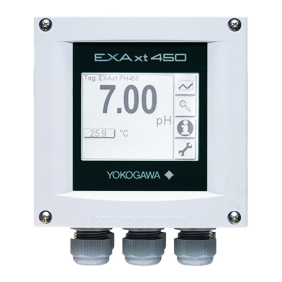
<4. OPERATION> 4. OPERATION Main display functions T ag:EXAxt PH45 0 Go to trend screen Go to zoom screen Go to status screen 25.0 W AS H 236.0 mV HOLD Go to maintenance screen Figure 4.1 Main Display A heart “ ”... -
Page 38: Zoom In On Details
<4. OPERATION> Zoom in on details This button gives access to the diagnostic information of the converter. The following messages will appear under normal (default) conditions: - Home key back to main screen. - One level up. - Scroll choices (grey means deactivated). Next - Enter selected data or choice. -
Page 39: Zero
<4. OPERATION> 4.3.3 Zero Calibrated sensor offset in mV. Theoretically the sensor reads 0 mV in a buffer solution with the same pH value as the Isopotential pH value of the sensor (default 7.00 pH). The ZERO value indicates the condition of the sensor. If the value exceeds +/- 120 mV (or user defined limits) an error message is displayed after calibration and the calibration is rejected. The trend of ZERO drift during the lifetime of the sensor is used to predict the lifetime of the sensor. -
Page 40: Projected Calibration
4.3.13 HART Device revision Sometimes the firmware of a device is updated in a way that the communication file (HART DD) need revision too. In this case the revision level is increased by one. The revision level of the HART DD must match the revision level of the Firmware. The revision level is expressed by the first two characters of the filename. The following files should be used when the HART Device revision level is 2. (0201.aot, 0201.fms, 0201.imp, 0201.sym) 4.3.14 Logbook The PH450G contains several logbooks to store history information on events, changed settings and calibrations. The logbooks have been categorized to simplify the retrieval of this information. IM 12B07C05-01E... -
Page 41: Information Function
2) Monitor the sensor(s) lifetime. Sensor will give all history information on parameter settings concerning the sensor(s). The events logged in this logbook are user definable. This is done in Commissioning >> Configure Logbook >> Sensor Logbook. Predictive maintenance. If the sensor diagnostics of the PH450G are enabled, the diagnostics are saved into this logbook. For the PH450G, the reference impedance (measured between the Liquid earth and the reference electrode) is stored every hour. This information can be used for (predictive) maintenance schedules as the impedance is a measure of fouling and the sensor should be kept clean for best results. -
Page 42: Secondary-Primary Value Display Switch
<4. OPERATION> Secondary-primary value display switch Pressing on this text block automatically switches the secondary value to the main display (Large font size). 25.0 Navigation of the menu structure Main display Primary setup display Instrument in HOLD Commissioning menu “HOME KEY” return to main display IM 12B07C05-01E... -
Page 43: Setup Concentration Mode
<4. OPERATION> Setup Concentration mode The concentration mode allows the user to generate an analog output signal that is linear to concentration units and to read the concentration on the LCD in the units %, mg/l or ppt. Example: PH450G is used as ORP analyzer and the output is linear to mg/l Free Chlorine. As first step the table for mA1 must be filled in. Then the concentration menu is opened: and begin and end value of the scale are entered Setup is completed. The measured concentration is now displayed on the top line of the LCD. IM 12B07C05-01E... - Page 44 Blank Page...
-
Page 45: Menu Structure Commissioning
<5. MENU STRUCTURE COMMISSIONING> 5. MENU STRUCTURE COMMISSIONING On Measurement setup , define parameters. The access to the Measurement setup can be secured by password. If you use password, store the password information at a safe place. When you start up the operation of the instrument, parameters are default values given at the factory. Define the parameters to suit the user’s preference or purposes such as type of combination or sensors to use. -
Page 46: Measurement Setup
Matrix The PH450G is equipped with a matrix type algorithm for accurate temperature compensation in various applications. Select the range as close as possible to the actual temperature/pH range. The PH450G will compensate by interpolation and extrapolation. - Page 47 <5. MENU STRUCTURE COMMISSIONING> NOTE ‘Sensor type’ and ‘Measurement’ determine the rest of the HMI menu structure. Range Menu Parameter Default values min. max. Manual Manual Temp. 25ºC, 77ºF -30ºC, -22ºF 139ºC, 284ºF Temp. Reference 25ºC, 77ºF 0ºC, 32ºF 100ºC, 211ºF comp.
-
Page 48: Calibration Settings
<5. MENU STRUCTURE COMMISSIONING> Calibration settings Calibration settings for a pH converter involve slope (sensitivity), zero (aspot) and ITP (iso thermal point). The following figure shows the pH value to the mV output of the sensor. Characteristic for pH measurement is an offset also known as aspot [mV] or zero [pH] and a Slope [mV/pH]. For an ideal sensor the theoretical slope is 59.16 mV/pH at 25ºC. Slope can be entered in mV/pH or a percentage of the theoretical slope (100% corresponds to 59.16 mV/pH). ITP is where the output of the sensor does not change with temperature. - Page 49 <5. MENU STRUCTURE COMMISSIONING> Range Menu Parameter Default values min. max. Limits and timing Zero high 120 mV 0 mV 532.4 mV 2.03 pH 0 pH 9 pH (relative to I.T.P.) Zero low -120 mV -532.4 mV 0 mV -2.03 pH 9 pH 0 pH (relative to I.T.P.) Slope high 110%...
-
Page 50: Impedance Setting
NOTE it is not necessary to enter this data. In most cases as the PH450G automatically does this while performing a calibration. The feature is used in the case of special electrode systems and where calibration in the process environment is not possible. - Page 51 <5. MENU STRUCTURE COMMISSIONING> mA2 similar structure to mA1 Range Menu Parameter Default values min. max. mA1 (control) Expire time 0.0 sec. 0.0 sec. 1800 sec. mA1 (output) Damping time 0.0 sec. 0.0 sec. 3600 sec. mA1 (simulate) Simulation perc. 50 % 100 % P(ID)-control mA1 Setpoint 7.00 pH (-99.99 pH)*...
- Page 52 <5. MENU STRUCTURE COMMISSIONING> Proportional control Proportional Control action produces an output signal that is proportional to the difference between the Setpoint and the PV (deviation or error). Proportional control amplifies the error to motivate the process value towards the desired setpoint. The output signal is represented as a percentage of output (0-100%). Proportional control will reduce but not eliminate the steady state error. Therefore, proportional Control action includes a Manual Reset. The manual reset (percentage of output) is used to eliminate the steady state error.
- Page 53 <5. MENU STRUCTURE COMMISSIONING> S2, S3, S4 Similar structure to S1 Range Menu Parameter Default values min. max. PID-control S1 Setpoint 7.00 pH (-99.99 pH)* (99.99 pH)* Range 1.00 pH (-99.99 pH)* (99.99 pH)* P(ID)-control S1 Manual Reset 0.000% 0.000% 100.0% PI(D)-control S1 I-time 3600 sec. 1 sec. 3600 sec.
-
Page 54: Contact Output Setup
5-10 <5. MENU STRUCTURE COMMISSIONING> Damping time The response to a step input change reaches approximately 90 percent of its final value within the damping time. range 100% Direct manual reset process point value range 100% Reverse manual reset process point value Figure 5.2 Direct/Reverse action... - Page 55 5-11 <5. MENU STRUCTURE COMMISSIONING> Enabled Disabled (see chapter 6) Disabled+Imp2 high for wash setup Enabled+Imp2 high S2, S3, S4 Similar structure to S1 Range Menu Parameter Default values min. max. Generic wash settings Interval time 6.0 hour 0.1 hour 36 hour Wash time 0.5 min.
- Page 56 5-12 <5. MENU STRUCTURE COMMISSIONING> l Configure hold Hold is the procedure to set the outputs to a known state when going into commissioning. Du r ing commissioning HOLD is always enabled, out p uts will have a fixed or last value. During ca l ibra t ion the same HOLD function applies. For ca l ibra t ion, it is up to the user if HOLD is enabled or not. Setpoint Hys. Delay time Delay time t (sec)
- Page 57 5-13 <5. MENU STRUCTURE COMMISSIONING> IM 12B07C05-01E...
-
Page 58: Fail
5-14 <5. MENU STRUCTURE COMMISSIONING> Lifetime contacts One should note that the lifetime of the contacts is limited (10 ) When these contacts are used for control (pulse frequency or duty cycle with small interval times) the lifetime of these contact should be observed. On/Off control is preferred over Pulse/duty cycle. Fail A fail contact is energized when a fail situation occurs. Fail situations are configured in section 5.10. For SOFT Fails the contact and the display on LCD are pulsating. For HARD Fails the contact and the display on LCD are energized continuously. Only contact S4 is programmed as a fail-safe contact. - Page 59 5-15 <5. MENU STRUCTURE COMMISSIONING> Range Menu Parameter Default values High HART Network address IM 12B07C05-01E...
-
Page 60: Logbook Configuration
Yokogawa Europe website. 5.13 Advanced setup Defaults The functionality of the PH450G allows to save and load defaults to come to a known instrument setting. The PH450G has both factory and user defined defaults. After a “load default” the instrument will reset. The following parameters are not included in the defaults 1. - Page 61 5-17 <5. MENU STRUCTURE COMMISSIONING> Range Menu Parameter Default values High Y-axis pH low 0.00 pH (-99.99 pH)* (99.99 pH)* pH high 14.00 pH (-99.99 pH)* (99.99 pH)* ORP low -1500 mV (-9999 mV)* (9999 mV)* ORP high 1500 mV (-9999 mV)* (9999 mV)* rH low -999. rH (0.00 rH)* (99.99 rH)* rH high...
-
Page 62: Display Setup
5-18 <5. MENU STRUCTURE COMMISSIONING> HART The address of the PH450G in a HART network can be set. Valid addresses are 0...15. FACTORY ADJUSTMENT This menu is for service engineers only. This section is protected by a password. Attempting to change data in the factory adjustment menu without the proper instructions and equipment, can result in corruption of the instrument setup, and will impair the performance of the unit. -
Page 63: Calibration
2- A second point can be set to determine the slope (sensitivity). Automatic calibration mode The PH450G will provide prompts to aid the user to make a good calibration. High quality buffer solutions must be used for best results. The user selects the buffer type that he is using in the calibration menu. The buffer set is selected in Commissioning >>... -
Page 64: Sample Calibration Mode
<6. CALIBRATION> We advise to leave the sensors for 3~5 minutes in the buffer solution before proceeding, even when the measurement is stable. This will give reliable and accurate calibration results. Sample calibration mode This mode is used first to record an instantaneous value for a grab sample. The sample value is held in memory, and normal measurement and control can continue, while the sample is analyzed. -
Page 65: Orp & Rh Calibration
How to check the ORP electrode is normal or not, see Appendix 5. Refer to the user manual of the ORP electrode for the proper calibration method. Operation of hold function during calibration PH450G has a HOLD function that will suspend the operation of the control/alarm relays and mA-outputs. During calibration, the user may choose to enable HOLD so that the output signals are frozen to a “last” or “fixed” value. Some users will choose to leave the outputs “live” to record the calibration event. - Page 66 <6. CALIBRATION> Termination of a wash cycle The user can decide to terminate the current wash cycle. This is done in the main screen (all other screens are deactivated) by pressing the wash flag (once or twice). The wash cycle has two time intervals (T and T ) and depending on the moment of pressing the “wash” flag the current interval is ended (see figure 6.1.) NOTE Recovery time is intended to let the sensor system recover to “Normal” process conditions. Interval time ended Measuring Wash Mode Mode WASH HOLD WASH HOLD Recovery Mode Figure 6.1 Wash cycle...
- Page 67 <6. CALIBRATION> NOTE When this setup is chosen special care should be taken in reference to scaling when the wash cycle is terminated. NOTE In this configuration manual wash is not applicable. Diagnostics The response time is a good diagnostic tool to see the condition of the electrode system. During the recovery time the response is monitored and an error is generated when the “half time value”...
- Page 68 Blank Page...
-
Page 69: Maintenance
Battery The PH450G converter contains a logbook feature that uses a clock to provide the timings. The instrument contains a lithium cell (battery) to support the clock function when the power is switched off. The cell has an expected working life of 10 years. Should this cell need to be replaced, contact your nearest Yokogawa service center. -
Page 70: Lcd Adjustment
LCD adjustment Contrast adjustment During the life of the analyzer the contrast of the display may fade. The contrast can be adjusted using the potentiometer on the backside of the LCD board. This adjustment must be done only by Yokogawa’s service personnel. The position is shown on the picture below. For units manufactured after July 2007, the potentiometer is placed behind the little hole in the LCD bracket as shown in Figure 3.4. IM 12B07C05-01E... - Page 71 <7. MAINTENANCE> For units manufactured between April 2006 and April 2007, the potentiometer is located as shown below. Touchscreen adjustment CAUTION A few years after using, the touchscreen may deviate from the correct position due to aging deterioration of the touchscreen. When that happens, turn off power then on again. The touchscreen will be calibrated automatically to the correct touch position at power on.
- Page 72 Blank Page...
-
Page 73: Troubleshooting
Incorrect programming by the user will also result in an error, explained in a message, so that the fault can be corrected according to the limits set in the operating structure. The PH450G also checks the sensor system to establish whether it is still functioning properly. -
Page 74: Error Displays And Actions
<8. TROUBLESHOOTING> Error displays and actions All errors are shown in the “Main Display” screen, however, the PH450G makes a distinction between diagnostic findings. The error messages may be set to OFF, WARN or FAIL. For process conditions where a particular diagnostic may not be appropriate, the setting OFF is used. FAIL gives a display indication only of that the system has a problem and inhibits the relay control action, and can be set to trigger the “Burn” function. “Burn-up or Burn-down” drives the mA output signal to 21 mA or 3.6 mA respectively. -
Page 75: Appendixes
APP-1 <APPENDIXES> APPENDIXES Appendix 1 Buffer tables Buffer tables NIST (IEC 60746-2)/DIN 19266 °C 1,68 pH 1.668 1.670 1.672 1.675 1.679 1.683 1.688 1.691 1.694 1.700 4,01 pH 4.003 3.999 3.998 3.999 4.002 4.008 4.015 4.024 4.030 4.035 4.047 6,87 pH 6.984 6.951 6.923 6.900 6.881 6.865 6.853 6.844 6.840 6.838 6.834 9,18 pH 9.464 9.395 9.332 9.276 9.225 9.180 9.139 9.102 9.081 9.068 9.038 °C 1,68 pH 1.707 1.715 1.723 1.743 1.766 1.792 1.806... - Page 76 The data concerning the pH temperature characteristic will need to be obtained from the supplier of the buffers. NOTE Yokogawa recommend the use of NIST (primary buffer standards) rather than buffers which have been adjusted by the addition of acid or alkaline materials to the buffer composition. In this way the customer gets a recognized standard, as well as the best buffer capacity (the ability to resist pH change with contamination).
-
Page 77: Appendix 2 Hart Hht (275/375) Menu Structure
APP-3 <APPENDIXES> Appendix 2 HART HHT (275/375) menu structure Those items with asterisks(*) appear or display each content variously depending on the selection of sensor type, measure type , output type and others. Online menu Level 1 menu Level 2 menu Level 3 menu Level 4 menu Process Primary value (pH)* values Secondary value (Temp.) Tertiary value (ORP/Hr)* Zoom Zoom sensor Zero* Slope* Sensor mV*... - Page 78 APP-4 <APPENDIXES> Online menu Level 1 menu Level 2 menu Level 3 menu Level 4 menu Commissioning Sensor setup Sensor type Measurement setup Meas type* Temp settings Temp sensor Temp unit Temp Temp comp compensation Man value* Ref temp Comp method* ORP comp method* ORP TC* Calib.
- Page 79 APP-5 <APPENDIXES> Online menu Level 1 menu Level 2 menu Level 3 menu Level 4 menu Output setup mA1 setup Type = control func Type = output func mA2 setup Process parameter Process parameter (similar to mA1) PID SP Lin 0%* PID Rng Lin 100%* PID dir Burn...
-
Page 80: Appendix 3 Temperature Compensation Matrix
Fld dev rev Sofware rev Poll addr Num req preams (*1): A part of the HART device ID (descriptor). (*2): Make sure to exit/cancel the loop test before proceeding to a measurement. NOTE HART protocol DD files can be downloaded by following URL. https://www.yokogawa.com/library/documents-downloads/software/ Go to the URL above and enter "PH450." Appendix 3 Temperature compensation matrix A minimum number of values is required to make interpolation possible. The highlighted values marked as are mandatory to enter. Tref Sol1... - Page 81 If an error is found, the PH450G will specify the location of the error as shown in the user interface screen above. The backspace key should be used for deleting an individual matrix value.
-
Page 82: Appendix 4 Control Drawing For Fm Approval
APP-8 <APPENDIXES> Appendix 4 Control drawing for FM approval IM 12B07C05-01E... -
Page 83: Appendix 5 Orp Electrode Check
ORP Electrode test solution A solution of known ORP (Oxygen Reduction Potential) is used. Usually quinhydrone or ferric chloride solution is used as the test solution. Yokogawa sells the following chemicals for making test solution. The procedure for mixing solution is described below. Quinhydrone salts (P/N K9024EC) and Ferrous & Ferric salts (P/N K9024ED) Procedure for ORP Electrode Test You determine whether or not the ORP sensor is normal by measuring the ORP of a test solution of known ORP and determining if the measured value is within tolerance. - Page 84 APP-10 <APPENDIXES> Ferrous & Ferric solution Tolerance Quinhydrone solution Tolerance Temperature C Figure ap1 ORP of Test Solution (7) Replace the sensor in its holder. CAUTION Be careful to make sulfuric acid solution. IM 12B07C05-01E...
-
Page 85: Parts List
Customer Model PH450G pH/ORP Converter Maintenance Parts List [Style: S2] 5a, 5b 6a, 6b 1a, 1b Item Part No. Description K9676GA Power board assembly AC version K9676HA Power board assembly DC version K9676EB Main board assembly PH version K9676MA LCD module K9676MX Cable assembly (3 core) - Page 86 Pipe/Wall Mounting Hardware (Option code: /U) Panel Mounting Hardware (Option code: /PM) UNIVERSAL MOUNT SET (Option code : /UM) includes both “/U” and “/PM”. Awning Hood (Option code: /H5) Item Part No. Description K9171SS Mounting Set (/U) Y9608KU Screw D0117XL-A U-Bolt Assembly K9171SY Plate...
-
Page 87: Revision Record
Revision Record Manual Title : Model PH450G pH/ORP Converter [Style: S2] Manual Number : IM 12B07C05-01E Nov. 2017 Added explanation and attention (page 5-1). Modified min. and max. values (pages 5-7, 5-9, 5-17). Aug. 2017 Added RoHS, All reviewed. Mar. 2012 Revisions: PREFACE, Addition of “How to dispose the batteries”; p3 to 4, Some revision of N) Safety and EMC conforming standards (description for EMC revised);.p19, HART communication mark added to Figure 4-1; p44, Section 7-3 “Contrast adjustment” changed to “LCD adjustment”, some caution added; Customer Maintenance Parts List CMPL 12B07C05-... - Page 88 Published by Yokogawa Electric Corporation 2-9-32 Nakacho, Musashino-shi, Tokyo 180-8750, JAPAN http://www.yokogawa.co.jp/an KOHOKU PUBLISHING & PRINTING INC. n Printed by IM 12B07C05-01E...
Need help?
Do you have a question about the PH450G and is the answer not in the manual?
Questions and answers