Sign In
Upload
Manuals
Brands
YOKOGAWA Manuals
Transmitter
PH202S
YOKOGAWA PH202S Manuals
Manuals and User Guides for YOKOGAWA PH202S. We have
1
YOKOGAWA PH202S manual available for free PDF download: User Manual
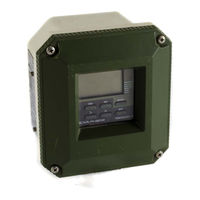
YOKOGAWA PH202S User Manual (138 pages)
2-wire Type pH/ORP(Redox) Transmitter
Brand:
YOKOGAWA
| Category:
Transmitter
| Size: 4 MB
Table of Contents
Table of Contents
2
Preface
6
Introduction and General Description
10
Instrument Check
10
Application
12
PH202 Specifications
14
General
14
Operating Specifications
15
Model and Suffix Codes
19
Control Drawing of PH202S Ma HART ® Specification (Iecex)
20
Control Drawing of PH202S Ma HART ® Specification (ATEX)
21
Control Drawing of PH202S Ma HART ® Specification
22
(FM Intrinsically Safe Design)
22
Control Drawing of PH202S Ma HART ® Specification
23
Control Drawing of PH202S Ma HART ® Specification (CSA)
24
Control Drawing of PH202S FF/PB Specification (Iecex)
25
Control Drawing of PH202S FF/PB Specification (ATEX)
26
Control Drawing of PH202S FF/PB Specification
27
Control Drawing of PH202S FF/PB Specification
29
Control Drawing of PH202S FF/PB Specification
31
Control Drawing of PH202S FF/PB Specification
32
Control Drawing of PH202S FF/PB Specification (CSA)
33
Installation and Wiring
34
Installation and Dimensions
34
Installation Site
34
Mounting Methods
34
Preparation
36
Cables, Terminals and Glands
36
Wiring of Sensors
37
General Precautions
37
Additional Precautions for Installations in Hazardous Areas
37
Installation In: Hazardous Area-Non-Incendive
38
Liquid Earth
38
Access to Terminal and Cable Entry
38
Wiring of Power Supply
38
General Precautions
38
Connection of the Power Supply
39
Switching the Instrument on
39
Wiring the Sensor System
40
Impedance Measurement Jumper Settings
40
Sensor Wiring
41
Connection Cable
42
Sensor Cable Connection with Special Grommet
43
Sensor Cable Connections Using Junction Box (BA10) and Extension Cable (WF10)
44
Connection VP Type Sensor
44
Operation; Display Functions and Setting
46
Operator Interface
46
Explanation of Operating Keys
47
Setting Passcodes
48
Passcode Protection
48
Display Examples
48
Display Functions
49
Display Functions Ph (Default)
49
Display Functions Ph (ORP)
50
Display Functions Ph (Rh)
51
Parameter Setting
52
Maintenance Mode
52
Manual Temperature Selection and Adjustment
53
Process Temperature Measuring in ORP Mode
54
Manual Activation of HOLD
55
Manual Impedance Check
56
Commissioning Mode
57
Output Range
57
Hold
57
Service
61
Notes for Guidance in the Use of Service Coded Settings
62
Parameter Specific Functions
62
Temperature Compensation and Measuring Functions
64
Calibration Functions
66
Ma Output Functions
69
User Interface
70
Communication Setup
72
General
72
Test and Setup Mode
72
Calibration
74
Automatic Calibration
74
Manual Calibration
74
Sample Calibration
74
Data Entry
74
Calibration Procedures
75
Automatic Calibration
75
Automatic Calibration with HOLD Active
76
Manual Calibration (2Nd Parameter Calibration)
77
Sample Calibration
79
Maintenance
81
Periodic Maintenance for the EXA Transmitter
81
Periodic Maintenance for the Sensor System
81
Calibration Procedures Are Described in Step-By-Step Detail in Chapter 6. However, Follow These Guidelines
82
Troubleshooting
83
Diagnostics
84
Off-Line Calibration Checks
84
On-Line Impedance Checks
84
Spare Parts
86
Appendix
87
User Setting Table
87
Configuration Checklist for PH202G
89
Setup for Sensor Compatibility
90
General
90
Selection of Measurement and Reference Electrode
90
Selecting a Temperature Sensor
90
Set up for Other Functions
91
Set up for Pfaudler Type 18 Sensor
92
General Set up
92
Calibration Set up
92
Device Description (DD) Menu Structure
93
Glossary 11
97
Preface
98
Wiring Diagrams
99
Example of Non-Explosionproof System
99
Example of Intrinsically Safe Explosionproof System
99
Sensor Wiring
99
Connection Cable
100
Sensor Cable Connection Using Terminal Box
102
PH201G*B Dedicated Distributor
102
Communication Setup
102
The Setting of Sending WASH Signal (*WASH)
103
How to Output Manual Wash Signal
105
Setting of Errors (FAIL Contact)
106
Calibration in ORP Mode
107
Electrode Check
107
Manual Calibration
108
Calibration with Sample
108
Data Entry
108
Calibration Procedure
109
Supplement of Troubleshooting
110
Error Codes
110
On-Line Impedance Checks
111
Supplement of Temperature Sensor
112
Auto-Return
112
Calend
112
How to Cancel Sample Calibration
112
Appendix 3 QUALITY INSPECTION
113
PH202G, PH202SJ 2-Wire Ph/Orp Transmitter
113
PH202S 2-Wire Ph/Orp Transmitter
117
PH202G, PH202S 2-Wire Ph/Orp Transmitter
121
(Fieldbus Communication)
121
PH202G, PH202S 2-Wire Ph/Orp Transmitter
125
(Profibus Communication)
125
Customer Maintenance Parts List (PH202G Style : S3)
129
Advertisement
Advertisement
Related Products
YOKOGAWA PH202G (S)
YOKOGAWA PH202GS
YOKOGAWA PH200
YOKOGAWA PH201G
YOKOGAWA PH8SM3
YOKOGAWA PH8EHP
YOKOGAWA PH8ECP
YOKOGAWA PH8HF
YOKOGAWA PH8HFF
YOKOGAWA PH92
YOKOGAWA Categories
Measuring Instruments
Test Equipment
Transmitter
Controller
Media Converter
More YOKOGAWA Manuals
Login
Sign In
OR
Sign in with Facebook
Sign in with Google
Upload manual
Upload from disk
Upload from URL