Sign In
Upload
Manuals
Brands
YOKOGAWA Manuals
Data Loggers
MW100
YOKOGAWA MW100 Manuals
Manuals and User Guides for YOKOGAWA MW100. We have
1
YOKOGAWA MW100 manual available for free PDF download: User Manual
YOKOGAWA MW100 User Manual (260 pages)
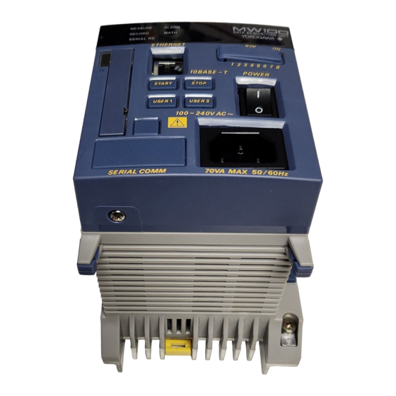
Data Acquisition Unit
Brand:
YOKOGAWA
| Category:
Data Loggers
| Size: 6 MB
Table of Contents
Foreword
2
Safety Precautions
3
Conventions Used in this Manual
5
Table of Contents
6
Chapter 1 Explanation of Functions
13
System Overview
13
MW100 Data Acquisition Unit
13
System Confi Guration
13
Main Module
16
Input/Output Modules
16
Base Plate
18
PC Software
19
MW100 Operation Guide
20
Functions of the Main Module
21
Names and Functions of Parts
21
Switches and Keys
22
Connectors
23
Displays
23
Measurement
25
Multi Interval
25
Filters
25
Math
26
MATH (/M1 Option)
26
Remote RJC (RRJC)
26
Burnout
26
Alarms
27
Operation Modes and Statuses
28
Tag Strings
28
Event Action Function
29
Daylight Saving Time
30
Timer
30
Match Time
30
Recording Operation
31
Saving Data to the CF Card
33
Communication Specifi Cations
35
E-Mail Function
36
Log Information
39
Functions of the 4-CH, High-Speed Universal Input Module
41
Measurement Input Types
41
Measurement Range
41
Measurement Interval, Integration Time, and Filter
43
Measurement Synchronization
43
Functions of the 10-CH, Medium-Speed Universal Input Module
44
Measurement Input Types
44
Measurement Range
44
Measurement Interval, Integration Time, and Filter
46
Measurement Synchronization
46
Functions of the 6-CH, Medium-Speed Four-Wire RTD Resistance Input Module
47
Measurement Input Types
47
Measurement Range
47
Measurement Interval, Integration Time, and Filter
48
Measurement Synchronization
48
Functions of the 4-CH, Medium-Speed Strain Input Module
49
Measurement Input Types
49
Measurement Range
49
Measurement Interval, Integration Time, and Filter
49
Measurement Synchronization
49
Initial Balancing (Unbalance Adjustment)
50
Scaling Settings of the Strain Gauge Type Sensor
51
Functions of the 10-CH, High-Speed Digital Input Module
53
Measurement Input Types
53
Measurement Range
53
Measurement Interval
53
Filters
53
Functions of the 8-CH, Medium-Speed Analog Output Module
54
Output Types
54
Output Method
54
Output Range
54
Output Update Interval
54
Operation Upon Startup and Errors
54
Output Operation During Calibration
54
Functions of the 8-CH, Medium-Speed PWM Output Module
55
Output Types
55
Output Method
55
Output Range and Output Waveform
55
Pulse Interval
55
Output Update Interval
55
Operation Upon Startup and Error Occurrence
55
Operation of the 8-CH Medium-Speed Analog Output Module and the 8-CH Medium Speed PWM Output Module
56
Output Upon Startup and Error Occurrence
56
Output Format
56
Output on Disabled Channels
56
Output Operation Per Settings and Setting Changes
56
Steady Output Operation
58
Output Operation During an Abnormality and after Recovery from the Abnormality
58
Functions of the 10-CH, Medium-Speed Digital Output Module
60
Output Types
60
Output Update Interval
60
Relay Excitation State / Hold Operation
60
Relay Operation
61
Refl Ash Function
61
MATH Function (/M1 Option)
62
Overview of the MATH Function
62
Number of MATH Channels
62
MATH Types
62
MATH Reference Channels
64
Computation Operation
66
Math Interval
66
Rolling Average
67
Math Span
67
Handling Units in Computations
67
Pulse Integration (TLOG.PSUM) Settings
67
Alarm Level
68
Math Error Data Processing
68
Chapter 2 Installation and Wiring
70
Handling Precautions
70
Installation
71
Installation Location
71
Installation Procedures
71
Attaching the Modules
73
Preparing the Base Plate
73
Attachment Procedure
73
Attachment Positions and Channel Numbers
74
Connecting Signal Wires
75
Terminal Arrangement Markings on the Terminal Cover
75
Attaching and Removing the Terminal Block
76
Attaching the Plate with Screw Terminal and Plate with Clamp Terminals for Current
77
Screw Terminal Block
77
General Precautions When Wiring the Input/Output Signal Wires
78
Wiring Procedures
81
Wiring the Universal Input Module
81
Wiring the 4-Wire RTD Resistance Input Module
82
Wiring the Strain Input Module
82
Wiring Digital Input Modules
86
Wiring with the Analog Output Module
87
Wiring with the PWM Output Module
87
Wiring with the Digital Output Module
88
Connecting the Power Supply and Turning the Power Switch on and off
89
Connections with the Power Cord
89
Code -1 *)
89
Wiring the Power Supply Terminal (Power Supply/Cord Basic Specifi Cation Code -1W)
90
Wiring the Power Supply Terminal (When the Suffi X Code of the Power Supply/Cord Is -2 * or -3W)
91
Turning the Power Switch on and off
92
Connecting the Ethernet Cable
93
Connection Procedure
93
Checking the Communication Status
93
Changing the Data Rate
93
Initializing Settings
93
Connecting the RS-422A/485 Interface (/C3 Option)
94
Terminal Wiring and Signal Names
94
Connection Procedure
94
Connecting the RS-232 Interface (/C2 Option)
97
Connector Pin Assignments and Signal Names
97
Handshaking
97
Measures against Noise on the MW100 Data Acquisition Unit
99
Integrating A/D Converter
99
First-Order Lag Filter
101
2.10 Handling of the CF Card
102
Handling Precautions of the CF Card
102
Inserting the CF Card
102
Ejecting the CF Card
102
Chapter 3 Setting and Data Acquisition
103
Connection Environment
103
PC System Requirements
103
Browser
103
Installing Java
103
MW100 Operation Screens
104
Host Name Display
105
Switching Modes
106
Connection to the MW100
107
Ethernet Connection
107
Connecting with Serial Communication (Optional)
109
Modbus/Rtu Settings
110
Modbus/Tcp Settings
112
Login Function and User Settings
114
System Settings
115
System Reconstruction
115
Setting the Date and Time
115
Viewing and Initializing the System Information
116
Formatting the CF Card and Checking the Free Space
116
Daylight Saving Time Setting
117
Other Settings
117
Status Information and Processing
118
Setting Acquisition Conditions for Measured/Computed Data
120
Measurement Operation Settings
120
Computation Operation Settings
121
Recording Operation Settings
122
Thinning Operation Settings
123
Recording Channel Settings
124
Data Save Folder Settings
124
Setting Measurement Conditions (Measurement Channel Settings)
125
Measurement Channel Settings
125
Global Channel Settings
127
Scale Input Methods
128
Filter and Thermocouple Settings
128
Setting up and Executing Strain Input Initial Balancing
129
MATH Settings (MATH Channel Settingsand the /M1 Option)
130
Entering Expressions
130
Global Expression Setting
131
Setting MATH Constants
131
Setting MATH Groups
131
Program Channel Settings
132
Communication Input Data Settings
132
Setting Alarms
133
Alarm Setting (AI/DI)
133
Alarm Setting (MATH)
134
Delay Alarm Setting
135
Digital Output Settings
136
Relay Settings
136
Analog/Pwm Output Settings
137
Output Range Settings (Analog Output)
137
Output Range Settings (PWM Output)
138
Global Channel Settings
139
Output Operation Settings
140
Transmission Output Control
141
3.10 Event/Action Settings
142
3.11 Timer and Match Time Settings
143
Timer Settings
143
Setting the Match Time
144
Starting and Stopping Measurement, Computation, and Recording
145
3.12 Starting and Stopping Measurement
145
Starting and Stopping Computation
146
Starting and Stopping Recording
146
Checking the Operating Status of the MW100 Using the Status Indicators
147
3.13 Network Utility Settings
148
DNS Client Settings
148
FTP Client Settings
148
Mail Client Settings
149
Time Synchronization Client Settings
151
Server Settings
152
3.14 Saving and Loading Setup Data
153
Setup Data Save Conditions
153
3.15 Measured Data Monitor Display/Settings
154
Monitor-Display of Measured Data
154
Explanation of Display Items
155
Display Settings
161
Log Information
165
Chapter 4 Troubleshooting and Maintenance
166
Error Display on the 7-Segment LED and Corrective Actions
166
Errors Upon Startup
166
System Errors
166
Module Errors
166
Communication Errors
167
Settings Errors
167
Execution Error
170
Execution Errors
170
Communication Command Error
171
Communication Error
172
System Errors
172
Error Display in the Monitor Screen and Corrective Actions
173
Troubleshooting
174
Calibration
177
Range Calibration for DC Voltage, RTD, Resistance, Strain, and Analog Output
177
Calibration of Temperature Measurements Using Thermocouples
181
Parts and Maintenance
182
System Initialization
183
Initialization Type
183
Initialization Procedure
183
Updating the System
184
Update Preparation
184
Updating Operation
184
Update Confi Rmation
185
Restoring the Settings
185
Chapter 5 Specifi Cation
186
Common Specifi Cations
186
Normal Operating Conditions
186
Transport and Storage Conditions
186
Mechanical Specifi Cations (Excluding AC Adapter)
186
Standards Compliance
186
Main Module Specifi Cations
187
Measurement
187
Math
188
MATH Function Specifi Cations (/M1 Option)
188
Rjc
191
Remote RJC
191
Alarms
192
Recorder Structure
193
Display
198
Communication
198
Modbus Protocol Specifi Cations
202
Event Action
206
Timer and Match Timer
206
User Interface
207
Other Functions
207
General Specifi Cations
209
External Dimensions
210
Base Plate Specifi Cations
211
External Dimensions
211
Attaching the MW100 Main Module
211
4-CH, High-Speed Universal Input Module Specifi Cations
212
Effects of Operating Conditions
215
General Specifi Cations
215
External Dimensions
215
10-CH, Medium-Speed Universal Input Module Specifi Cations
216
Effects of Operating Conditions
219
General Specifi Cations
219
External Dimensions
219
6-CH, Medium-Speed Four-Wire RTD Resistance Input Module Specifi Cations
220
Effects of Operating Conditions
222
General Specifi Cations
223
External Dimensions
223
4-CH, Medium-Speed Strain Input Module Specifi Cations
224
Effects of Operating Conditions
225
General Specifi Cations
227
External Dimensions
227
10-CH, High-Speed Digital Input Module Specifi Cations
227
General Specifi Cations
228
External Dimensions
228
External Dimensions
229
Output Span Setting
229
Handling Abnormal Data
229
8-CH, Medium-Speed PWM Output Module Specifi Cations
230
General Specifi Cations
231
External Dimensions
231
Handling Abnormal Data
231
Operations Common to the 8-CH Medium-Speed Analog Output Module and the 8-CH Medium Speed PWM Output Module
232
Settings Related Specifi Cations (by Module)
232
Overview of Output Operation When Setting Holding of Previous Value of Transmission Output
232
10-CH, Medium-Speed Digital Output Module Specifi Cations
233
General Specifi Cations
233
External Dimensions
233
Appendix
234
Appendix 1 Supported Characters
234
Appendix 2 Setting Data Communication that Uses Modbus Protocol
235
Setup Procedure
235
Example System
235
Setup Example
236
Client/Server Settings for READ
237
Appendix 2 Setting Data Communication that Uses Modbus Protocol 2
237
Client/Server Settings for WRITE
239
Starting Communication
240
Checking the Communication Status
241
Register Data Types
241
Appendix 3 Using the Event Action
242
Saving Data on the Hour
242
Acquiring Periodic Data
242
Diving the Data on each Event
243
Appendix 4 E-Mail Format
244
Alarm Notifi Cation E-Mail Format
244
File Creation Notifi Cation E-Mail Format
245
Media Remaining Space Notifi Cation E-Mail Format
246
Power on Notifi Cation E-Mail Format
246
Error Notifi Cation E-Mail Format
247
Periodic Report Notifi Cation E-Mail Format
248
Test E-Mail Format
249
Appendix 5 Retrieving Files Using Webdav
250
Connection Using a Browser
250
Appendix 6 Network Terminology
251
Appendix 7 Using the Broken Line Data of Decimal Values
252
Appendix 8 Saving Data to the CF Card
253
Write Timing
253
Replacing the CF Card While Recording
254
Write Count
255
Advertisement
Advertisement
Related Products
YOKOGAWA MX100
YOKOGAWA MX112
YOKOGAWA MX115
YOKOGAWA MX125
YOKOGAWA MX150
YOKOGAWA MX120
YOKOGAWA mR10000 436102
YOKOGAWA MVAdvanced MV1000
YOKOGAWA MVAdvanced MV2000
YOKOGAWA MG8E
YOKOGAWA Categories
Measuring Instruments
Test Equipment
Transmitter
Controller
Media Converter
More YOKOGAWA Manuals
Login
Sign In
OR
Sign in with Facebook
Sign in with Google
Upload manual
Upload from disk
Upload from URL