Sign In
Upload
Manuals
Brands
YOKOGAWA Manuals
Test Equipment
DL1740EL
YOKOGAWA DL1740EL Manuals
Manuals and User Guides for YOKOGAWA DL1740EL. We have
4
YOKOGAWA DL1740EL manuals available for free PDF download: User Manual, Service Manual
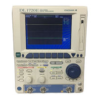
YOKOGAWA DL1740EL User Manual (454 pages)
DL1700E Series. Digital Oscilloscope
Brand:
YOKOGAWA
| Category:
Test Equipment
| Size: 8 MB
Table of Contents
Product Registration
2
Checking the Contents of the Package
4
Safety Precautions
7
Waste Electrical and Electronic Equipment
9
Conventions Used in this Manual
10
Flow of Operation
11
Table of Contents
12
Chapter 1 Names and Functions of Parts
17
Front Panel, Rear Panel, and Top Panel
17
Rear Panel
18
Panel Keys and Knobs
20
Display Screens
24
Chapter 2 Explanation of Functions
27
System Configuration and Block Diagram
27
Vertical and Horizontal Axis
29
Triggers
34
Waveform Acquisition and Display Conditions
40
Other Waveform Display Settings
46
Waveform Computation
47
Power Spectrum Display
48
Analyzing, and Searching Waveforms
49
Automated Measurement of Waveform Parameters, GO/NO-GO Determination
54
Communication
56
Communication Using Commands (GP-IB, USB, or Ethernet)
56
Saving and Loading Data from a Network Drive (FTP Client)
56
Using the Instrument as a Network Drive
57
Other Useful Functions
58
Entering Values and Text Using the USB Keyboard
58
Operating the Instrument Using a Free Software Program
60
Chapter 3 Making Preparations for Measurements
61
Handling Precautions
61
Installing the Instrument
63
Connecting the Power Supply and Turning the Power Switch on and off
65
Connecting the Probe
68
Compensating the Probe (Phase Correction)
71
Setting the Date and Time
73
Chapter 4 Common Operations
75
Operations and Functions of Keys and the Jog Shuttle
75
Entering Values and Strings
77
Operating the Instrument Using a USB Keyboard or a USB Mouse
80
Initializing Settings
87
Executing Auto Setup
89
Performing Calibration
92
Correcting the Delay Time of the Input Signals
94
Using the Help Function
96
Chapter 5 Vertical and Horizontal Axes
97
Turning Channels on and off
97
Setting V/DIV
98
Setting the Vertical Position of the Waveform
100
Setting the Input Coupling
102
Selecting the Probe Attenuation/Current-To-Voltage Conversion Ratio
104
Setting the Offset Voltage
105
Using the Preset Function
107
Setting the Bandwidth Limit
110
Using the Linear Scaling Function
111
Selecting the Time Base
113
Setting T/DIV
115
Chapter 6 Triggers
116
Selecting the Trigger Mode
116
Setting the Trigger Position
118
Setting the Trigger Delay
120
Setting the Hold off Time
121
Setting the Edge Trigger (SIMPLE)
123
Setting the External Trigger (SIMPLE)
126
Activating Triggers on the Commercial Power Supply (SIMPLE)
128
Setting the A->B(N) Trigger (ENHANCED)
129
Setting the a Delay B Trigger (ENHANCED)
132
Setting the Pattern Trigger (ENHANCED)
135
Activating a Width (Pulse<T, Pulse>T, T1<PLS<T2, and Time Out) Trigger (ENHANCED)
139
Setting the or Trigger (ENHANCED)
143
Setting a Window Trigger (ENHANCED)
146
Setting the TV Trigger (ENHANCED)
149
Setting the Action-On-Trigger
153
Setting the Trigger Gate
155
Chapter 7 Waveform Acquisition
157
Starting/Stopping Waveform Acquisition
157
Setting the Record Length
158
Using Interleave Mode
159
Turning Repetitive Sampling Mode on and off
160
Setting the Acquisition Mode
161
Performing Sequential Store (SINGLE(N) Mode)
164
Chapter 8 Waveform Display and Information Display
166
Changing the Display Format
166
Setting the Display Interpolation Method
168
Accumulating Waveforms
170
Zooming the Waveform
172
Displaying the X-Y Waveform
175
Taking Snapshots and Clearing Traces
178
Changing the Graticule (Scale)
179
Turning the Scale Display on and off
180
Setting Waveform Labels
181
Turning the Translucent Display on and off
183
Chapter 9 Waveform Computation
184
Displaying and Labeling Computed Waveforms
184
Adding, Subtracting, and Multiplying Waveforms
186
Performing Binary Computation
189
Inverting Waveforms
191
Differentiating and Integrating Waveforms
193
Performing Power Spectrum Computation (FFT)
195
Smoothing Waveforms
197
Shifting the Phase
199
Chapter 10 Analyzing and Searching Waveforms
201
Displaying History Waveforms
201
Searching the History Waveforms Using Zones (History Search)
205
Searching the History Waveforms Using Automatic Measurement of Parameters (History Search)
210
Searching Waveforms Using the Search and Zoom Function
214
Cursor Measurements
231
Automated Measurement of Waveform Parameters
241
Statistical Processing of the Automated Measurement Values of Waveform Parameters
248
Performing Automated Measurements of Waveform Parameters on Dual Areas
255
Performing GO/NO-GO Determination Using Zones
260
Performing GO/NO-GO Determination Using Automated Measurement of Waveform Parameters
266
Using the GO/NO-GO Determination Signal Output Function
270
Chapter 11 Printing Screen Images
272
Installing the Roll Paper into the Built-In Printer (Optional)
272
Printing Using the Built-In Printer (Optional)
274
Printing Using a USB Printer
277
Printing Using a Network Printer (Optional)
281
Chapter 12 Saving and Loading Data
284
Storing and Recalling Setup Data
284
Floppy Disks and PC Cards
286
Connecting USB Storage (MO Disk Drive, Hard Disk, Flash Memory) to the USB PERIPHERAL Interface
289
Formatting the Storage Medium
291
Saving/Loading the Waveform Data
295
Saving/Loading Settings
303
Saving/Loading the Snapshot Waveforms
309
Saving Automated Measurement Values of Waveform Parameters
313
Saving Screen Image Data
316
Thumbnails of the Saved Screen Image Data Can be Displayed
320
Changing the File Attributes and Deleting Files
325
Copying Files
329
Changing the Directory or File Name of the Storage Medium and Creating Directories
333
Chapter 13 Ethernet Communications (Optional)
337
Connecting the Instrument to the Network
337
Setting up the TCP/IP
339
Saving and Loading Waveform Data, Setup Data, and Image Data on a Network Drive (FTP Client Function)
344
Entering Settings for Printing Screen Images on the Network Printer (LPR Client Function)
348
Sending Periodic or Action Mail (SMTP Client Function)
349
Accessing the Instrument from a PC or Workstation (FTP Server Function)
354
Using the Web Server Function
356
Setting the Time Difference from GMT (Greenwich Mean Time)
381
Checking the Presence of the Ethernet Interface (Optional) and the MAC Address
384
Setting the FTP Passive Mode and LPR/SMTP Timeout
385
Using the Instrument as a Network Drive
387
Chapter 14 Rear Panel Auxiliary I/O Section
389
External Trigger Input, External Clock Input, and Trigger Gate Input
389
Trigger Output (TRIG OUT)
392
Video Signal Output (VIDEO out (VGA))
394
Chapter 15 Other Operations
395
Changing the Message and Menu Language and Turning the Click Sound on and off
395
Changing the USB Keyboard Language and Checking the Connected USB Keyboard
397
Measuring the Offset Voltage and Applying the Offset Voltage to the Computed Results
399
Setting the Screen Color and Intensity
400
Turning off the Backlight and Setting the Brightness of the Backlight
403
Chapter 16 Troubleshooting, Maintenance, and Inspection
405
Malfunction? First, Investigate
405
Messages and Corrective Actions
406
Error Messages
406
Performing a Self-Test
411
Display an Overview of the System Conditions (Overview)
414
Replacing the Power Fuse
415
Recommended Replacement Parts
416
Chapter 17 Specifications
417
Input Section
417
Trigger Section
419
Time Axis
420
Display
421
Functions
421
Built-In Printer (Optional)
424
Storage
424
USB Peripheral Interface
424
Auxiliary I/O Section
425
Computer Interface
426
General Specifications
427
Dimensional Drawings
429
Appendix
430
Appendix 1 Relationship between the Time Axis Setting, Sample Rate and Record Length
431
Appendix 2 How to Calculate the Area of a Waveform
440
Appendix 3 ASCII Header File Format
444
Appendix 4 List of Default Values
446
Appendix 5 Key Assignments of the USB Keyboard
447
Advertisement
YOKOGAWA DL1740EL User Manual (186 pages)
Digital Oscilloscope Communication Interface
Brand:
YOKOGAWA
| Category:
Test Equipment
| Size: 2 MB
Table of Contents
Foreward
2
How to Use this Manual
4
Conventions Used in this Manual
5
Table of Contents
7
Chapter 1 Overview of the GP-IB Interface
9
Names of the Parts and Their Functions
9
Connection Via the GP-IB Interface
10
GP-IB Interface Functions
11
GP-IB Interface Specifications
12
Setting up this Instrument (GP-IB)
13
Response to Interface Messages
14
Chapter 2 USB Interface
16
Names of the Parts and Their Functions
16
USB Interface Functions and Specifications
17
Connection Via the USB Interface
19
Setting up this Instrument (USB)
20
Chapter 3 Ethernet Interface (Option)
21
Names of the Parts and Their Functions
21
Ethernet Interface Functions and Specifications
22
Connection Via the Ethernet Interface
24
Setting up this Instrument (Network)
25
Chapter 4 Before Programming
27
Messages
27
Commands
29
Response
31
Data
31
Synchronization with the Controller
34
Chapter 5 Commands
36
A List of Commands
36
Acquire Group
50
Asetup Group
52
Calibrate Group
52
Channel Group
54
Clear Group
57
Communicate Group
58
Cursor Group
60
Display Group
68
FILE Group
73
Gonogo Group
79
Hcopy Group
87
History Group
90
Image Group
95
Initialize Group
97
MATH Group
98
Measure Group
101
Phase Group
113
Preset Group
114
Recall Group
117
Search Group
118
SNAP Group
127
Sstart Group
127
Start Group
127
Status Group
128
Status Report
128
STOP Group
129
Store Group
130
System Group
131
Timebase Group
134
Trigger Group
135
Waveform Group
146
XY Group
149
ZOOM Group
151
Common Command Group
153
Chapter 6 Status Report
156
Overview of the Status Report
156
Status Byte
157
Standard Event Register
158
Extended Event Register
159
Output Queue and Error Queue
160
Chapter 7 Sample Program
161
Before Programming
161
Sample Programs
161
Image of Sample Program
162
Initialize/Error/Execute
163
Sets/Queries the T/DIV
166
Data Output in Word Format (2 Bytes)
168
Sets/Queries Measure Value
171
Appendix 1 ASCII Character Code
174
Appendix
174
Appendix 2 Error Messages
175
Appendix 3 Overview of IEEE 488.2-1992
177
Appendix 4 Waveform Parameter Name Correspondence Table
179
Command List
182
YOKOGAWA DL1740EL User Manual (107 pages)
Digital Oscilloscope. Serial Bus Signal Analysis Function
Brand:
YOKOGAWA
| Category:
Test Equipment
| Size: 0 MB
Table of Contents
Conventions Used in this Manual
3
Table of Contents
4
Chapter 1 I 2 C Bus Signal Analysis Function
5
Overview of the I
5
Bus Signal Analysis Function
5
Flow of Operation
6
Connecting the Probe
7
Setting the I C Bus Signal Acquisition Conditions
10
Setting the Start Condition or Stop Condition
10
Setting the Combination Trigger
11
Setting the Trigger Level, Trigger Coupling, Etc
13
Setting the Trigger Mode
13
Setting the Record Length
13
Starting/Stopping the I C Bus Signal Acquisition
13
Examples of Setting the Trigger Conditions of the I2C Bus Signal
19
Analyzing/Searching Data
29
Saving the Data of the Detailed Analysis List
39
Error Messages
41
Communication Commands
42
Chapter 2 SPI Bus Signal Analysis Function
55
Overview of the SPI Bus Signal Analysis Function
55
Flow of Operation
57
Connecting the Probe
58
Setting SPI Bus Signal Acquisition Conditions
59
Setting the Trigger Conditions of the SPI Bus Signal
59
Setting the Trigger Level, Trigger Coupling, Etc
62
Setting the Trigger Mode
62
Setting the Record Length
62
Examples of SPI Bus Signal Trigger Conditions
66
Analyzing/Searching Data
73
Saving the Data of the Detailed Analysis List
86
Error Messages
88
Communication Commands
89
Chapter 3 Specification
103
I 2 C Bus Signal Analysis Function
103
SPI Bus Signal Analysis Function
105
Advertisement
YOKOGAWA DL1740EL Service Manual (73 pages)
Digital Oscilloscope
Brand:
YOKOGAWA
| Category:
Test Equipment
| Size: 2 MB
Table of Contents
Safety Precautions
3
Overview of this Manual
5
Table of Contents
6
Chapter 1 Principles of Operation
8
Block Diagram
8
Function of each Assembly
10
Function of each ASIC
13
Chapter 2 Performance Testing
18
Introduction
18
Tests for the DL1720E/DL1740E/DL1740EL
19
Grounding Test
20
Insulation Resistance Test
21
Withstand Voltage
21
Selftest
21
GP-IB Test
22
Rear Panel Probe Power Supply Test
23
LINE Trigger, Trigger LED, and Hold off Test
23
Probe Compensation Output and Auto Setup Test
23
Timebase Accuracy Test
24
Input Signal Bandwidth
24
Trigger Sensitivity Test
25
Offset Accuracy
25
DC Accuracy
26
EXT Trigger Level Accuracy Test
27
EXT Trigger Sensitivity and Trigger out Test
28
EXT Clock Input Test
29
Chapter 3 Adjustments
30
Introduction
30
Test Environment
31
Equipment Required
32
DC Offset Adjustment on the AD Board
33
Flatness Adjustment on the Analog Board
36
Chapter 4 Troubleshooting
39
Introduction
39
Flow Chart
40
Assemblies to Check When an Error Occurs
41
Power Supply Secondary Voltage
44
Chapter 5 Schematic Diagram
45
Chapter 6 Customer Maintenance Parts List
46
Standard Accessories
50
Chapter 7 Procedures for Disassembly
51
Flow Chart of Disassembly
51
Removing the Top Cover
52
Removing the Fan Assy
53
Removing the Printer Case
54
Removing the CPU Board Assy
55
Removing the Printer Unit
56
Removing the Inverter Assy
59
Removing the Front Bezel
60
Removing the PC Card Drive/Fdd Assy
61
Removing the Key Board Assy
62
Removing the LCD
63
Removing the Power Supply Assy
64
Removing the Input Assy
66
Removing the AD Board Assy
69
Removing the Analog Assy/Et2 Assy
71
Removing the ACQ Board Assy
72
Removing the Ether Board Assy
73
Advertisement
Related Products
YOKOGAWA DL1720E
YOKOGAWA DL1740E
YOKOGAWA DL1735E
YOKOGAWA DL1700E Series
YOKOGAWA DL1720
YOKOGAWA DL1740
YOKOGAWA DL1620
YOKOGAWA DL1640L
YOKOGAWA DL1640
YOKOGAWA DL 1520L
YOKOGAWA Categories
Measuring Instruments
Test Equipment
Transmitter
Controller
Media Converter
More YOKOGAWA Manuals
Login
Sign In
OR
Sign in with Facebook
Sign in with Google
Upload manual
Upload from disk
Upload from URL