Sign In
Upload
Manuals
Brands
YASKAWA Manuals
DC Drives
CIMR-JB Series
YASKAWA CIMR-JB Series Manuals
Manuals and User Guides for YASKAWA CIMR-JB Series. We have
1
YASKAWA CIMR-JB Series manual available for free PDF download: Installation & Start-Up Manual
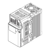
YASKAWA CIMR-JB Series Installation & Start-Up Manual (287 pages)
AC Drive, Compact V/f Control Drive, 200/400 V Class, Three-Phase Input: 0.1/0.2 to 5.5/2.2 kW
Brand:
YASKAWA
| Category:
DC Drives
| Size: 9.48 MB
Table of Contents
Table of Contents
3
Preface & General Safety
11
Preface
12
Applicable Documentation
12
Symbols
12
Terms and Abbreviations
13
General Safety
14
Supplemental Safety Information
14
Safety Messages
15
Drive Label Warnings
18
Warranty Information
18
Quick Reference
20
Receiving
21
Section Safety
22
Model Number and Nameplate Check
23
Nameplate
23
Component Names
26
Ip20/Open-Chassis
26
Front Views
28
Mechanical Installation
29
Section Safety
30
Mechanical Installation
33
Installation Environment
33
Installation Orientation and Spacing
34
Exterior and Mounting Dimensions
36
Electrical Installation
39
Section Safety
40
Standard Connection Diagram
43
Main Circuit Connection Diagram
46
Single-Phase 200 V Class Models BA0001 to BA0010
46
Three-Phase 200 V Class Models 2A0001 to 2A0020 Three-Phase 400 V Class Models 4A0001 to 4A0011
46
Terminal Block Configuration
47
Protective Covers
48
Ip20/Open-Chassis Cover Removal and Installation
48
Main Circuit Wiring
50
Main Circuit Terminal Functions
50
Wire Gauges and Tightening Torque
50
Main Circuit Terminal Power Supply and Motor Wiring
54
Control Circuit Wiring
57
Control Circuit Terminal Block Functions
58
Terminal Configuration
59
Wiring Procedure
61
I/O Connections
64
Sinking/Sourcing Mode Switch
64
Main Frequency Reference
67
DIP Switch S1 Analog Input Signal Selection
67
3.10 Braking Resistor
69
Installation
69
3.11 Interlocking with Connected Machinery
71
Drive Ready Signal
71
3.12 Wiring Checklist
72
Start-Up Programming & Operation
75
Section Safety
76
Using the Digital LED Operator
79
Keys, Displays, and Leds
79
Digital Text Display
81
LED Screen Displays
81
LO/RE LED and RUN LED Indications
82
Menu Structure for Digital LED Operator
84
The Drive and Programming Modes
85
Navigating the Drive and Programming Modes
86
Changing Parameter Settings or Values
90
Verifying Parameter Changes: Verify Menu
90
Switching between LOCAL and REMOTE
91
Parameters Available in the Setup Group
92
Start-Up Flowchart
93
Flowchart: Basic Start-Up
93
Basic Operation
94
Initialize Parameter Values: A1-03
94
Frequency Reference Source: B1-01
94
Run Command Input Selection: B1-02
96
Stopping Method Selection: B1-03
98
Acceleration/Deceleration: C1-01 to C1-04
99
Drive Duty and Carrier Frequency Selection: C6-01 and C6-02
103
E1: V/F Characteristics
107
Motor Parameters: E2-01 to E2-03
110
Digital Output: H2-01
111
Analog Outputs: H4-01 to H4-03
111
Motor Protection: L1-01 and L1-02
113
Notes on Controlling the Brake for the Hoist Application
116
Drive Status Monitors: U1-01 to U4-13
118
Powering up the Drive
119
Powering up the Drive and Operation Status Display
119
V/F Pattern Setting
120
Load Operation Test Run
121
Test Run with Load Connected
123
Test Run with the Load Connected
123
Verifying and Backing up Parameter Settings
124
Parameter Access Level: A1-01
124
Password Settings: A1-04, A1-05
124
Copy Function (Optional)
124
4.10 Test Run Checklist
126
Troubleshooting
127
Section Safety
128
Motor Performance Fine Tuning
131
Parameters for Tuning the Drive
131
Motor Hunting and Oscillation Control Parameters
132
Drive Alarms, Faults, and Errors
133
Types of Alarms, Faults, and Errors
133
Alarm and Error Displays
134
Fault Detection
137
Fault Displays, Causes and Possible Solutions
137
Alarm Detection
147
Alarm Codes, Causes, and Possible Solutions
147
Operator Programming Errors
152
Ope Codes, Causes, and Possible Solutions
152
Diagnosing and Resetting Faults
154
Fault Occurs Simultaneously with Power Loss
154
If the Drive Still Has Power after a Fault Occurs
154
Viewing Fault History Data after Fault
154
Fault Reset Methods
155
Troubleshooting Without Fault Display
156
Cannot Change Parameter Settings
156
Motor Does Not Rotate Properly after Pressing RUN Button or after Entering External Run Command
157
Periodic Inspection & Maintenance
167
Section Safety
168
Inspection
171
Recommended Daily Inspection
171
Recommended Periodic Inspection
173
Periodic Maintenance
175
Replacement Parts
175
Drive Cooling Fans
178
Number of Cooling Fans
178
Cooling Fan Replacement
179
Peripheral Devices & Options
183
Section Safety
184
Drive Options and Peripheral Devices
186
Drive Options and Peripheral Devices186
186
Connecting Peripheral Devices
189
Installing Peripheral Devices
191
Installing a Molded Case Circuit Breaker (MCCB) and Earth Leakage Circuit Breaker (ELCB)
191
Installing a Leakage Breaker
192
Installing a Magnetic Contactor
192
Connecting an AC or DC Reactor
193
Connecting a Surge Absorber
194
Connecting a Noise Filter
194
EMC Filter Installation
197
Zero-Phase Reactor
197
Installing Fuses on the Input Side
198
Attachment for External Heatsink
199
Noise Filter Installation
199
Installing a Motor Thermal Overload (Ol) Relay on the Drive Output
199
NEMA Type 1 Kit
202
Options
208
Interface Options
208
Other Options
208
Specifications
209
Heavy Duty and Normal Duty Ratings
210
Single/Three-Phase 200 V Class Drive
211
Three-Phase 400 V Class Drives
213
Drive Specifications
214
Drive Watt Loss Data
217
Drive Derating Data
219
Carrier Frequency Derating
219
Temperature Derating
219
Altitude Derating
220
Parameter List
221
Parameter Groups
222
Parameter Table
223
A: Initialization Parameters
223
B: Application
224
C: Tuning
225
D: References
228
E: Motor Parameters
230
H Parameters: Multi-Function Terminals
231
L: Protection Function
237
N: Advanced Performance Set-Up
241
O: Operator Related Parameters
241
U: Monitors
243
China Localized Drive Default Values
246
Defaults by Drive Model and Duty Rating ND/HD
247
Standards Compliance
251
Section Safety
252
European Standards
255
CE Low Voltage Directive Compliance
255
EMC Guidelines Compliance
258
UL Standards
264
UL Standards Compliance
264
Drive Motor Overload Protection
272
Precautions for Korean Radio Waves Act
274
한국 전파법에 관한 주의사항
275
Advertisement
Advertisement
Related Products
YASKAWA CIMR-JC
YASKAWA CIMR-JCBA0001
YASKAWA CIMR-JCBA0002
YASKAWA CIMR-JCBA0003
YASKAWA CIMR-JCBA0006
YASKAWA CIMR-JCBA0010
YASKAWA CIMR-E7U4220
YASKAWA CIMR-4A0007
YASKAWA CIMR-AC4A0058WAA
YASKAWA CIMR-AC4A0414AAA
YASKAWA Categories
Controller
DC Drives
Servo Drives
Robotics
Control Unit
More YASKAWA Manuals
Login
Sign In
OR
Sign in with Facebook
Sign in with Google
Upload manual
Upload from disk
Upload from URL