Sign In
Upload
Manuals
Brands
Yamatake Manuals
Measuring Instruments
MagneW3000 PLUS
User Manuals: Yamatake MagneW3000 PLUS Flowmeter
Manuals and User Guides for Yamatake MagneW3000 PLUS Flowmeter. We have
1
Yamatake MagneW3000 PLUS Flowmeter manual available for free PDF download: User Manual
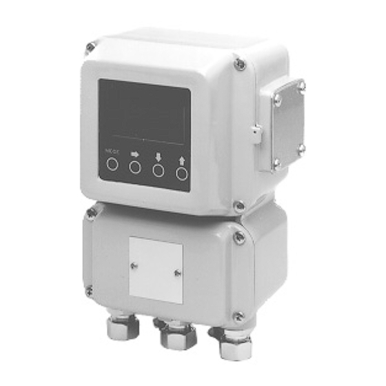
Yamatake MagneW3000 PLUS User Manual (134 pages)
Smart Electromagnetic Flowmeter
Brand:
Yamatake
| Category:
Measuring Instruments
| Size: 4 MB
Table of Contents
Table of Contents
9
Chapter 1 - Configuration and Structure of the Measuring Systems
14
Outline of this Chapter
14
System Configuration
15
Measuring System
15
Figure 1-1 Integral Configuration
15
Figure 1-2 Remote Configuration
16
Analog Output and Digital Output
17
System Configuration for Analog Output (4 - 20 Ma DC Output)
18
Figure 1-4 System Configuration for Analog Output with the Communication Function (Example Setup)
20
System Configuration for Digital Output (de Output)
21
Figure 1-5 System Configuration for Digital Output
21
Structure of this Unit and Functions of Parts
22
Structure of the Device
22
Figure 1-6 Structure of the Main Body
22
Approval of this Device
24
Chapter 2 - Installing the Device
26
Outline of this Chapter
26
Before Installation
27
Selecting the Installation Site (1)
27
Installation Method
28
Installing the Converter
28
Figure 2-1 Wall Mounted
28
Figure 2-2 2B Pipe Mounted
28
Figure 2-3 Integral Assembly
29
Electrical Wiring (1)
30
Electrical Wiring (2)
31
Figure 2-4 Terminal Arrangement for Remote Converter
31
Electrical Wiring (3)
32
Electrical Wiring (4)
33
Figure 2-5 Relation between Fluid Conductivity and Cable Length
33
Electrical Wiring (5)
34
Figure 2-6 Outer Dimensions of Signal Cables
34
Figure 2-7 Signal Cable Construction
34
Electrical Wiring (6)
35
Figure 2-8 Outer Dimensions of Excitation Cables
35
Figure 2-9 Excitation Cable Construction
35
Electrical Wiring (7)
36
Figure 2-10 Detector-To-Converter Connection
36
Figure 2-11 Wiring Diagram for Current Output
38
Figure 2-12 Wiring Diagram for Pulse Output
39
Figure 2-13 Wiring Diagram for Contact Input
40
Figure 2-14 Wiring Diagram for Contact Output
40
Chapter 3 - Operating and Stopping of the Measuring System
42
Outline of this Chapter
42
Start-Up
43
Preparations before Measurement
44
Zero Adjustment (1)
44
Method Using the Data Setting Device
45
Method Using the S-SFC
47
Stopping
48
Setting the Communication Function
49
Setting Write Protection
51
Setting the Empty Detection Function
52
Chapter 4 - Operation Using the Data Setting Device
54
Outline of this Chapter
54
Functions of the Data Setting Device
55
Data Setting Device
55
Figure 4-1 Names of Data Setter Parts
55
Operating the Display/Data Setting Device
58
Screen Organization
60
How to Skillfully Operate the Touch Key Switches
63
How to Enter the Operator's Mode
64
Operating in Operator's Mode
65
Resetting the Damping Time Constant
66
Zero Adjustment
67
Setting the Reset Value of the Built-In Flow Counter
69
Resetting the Built-In Flow Counter
70
Setting/Changing the Preset Value of the Built-In Flow Counter
71
Setting/Changing the Flow Rate Indication
72
Selecting Modes
73
Engineering Mode
75
Setting the ID
77
Selecting Functions
78
Relations for Setting Function FXXXX
80
Range Functions
84
Figure 4-2 Normal Direction Automatic Double Range
85
Figure 4-3 Normal/Reverse Automatic Switching Range
87
Built-In Counter Function
89
Contact Input Function
90
Contact Output Function
91
Detector Data Setup
94
Setting the Number of Dummy Detectors
96
Setting the Range
97
Setting Hysteresis
98
Selecting the Current Output Method
99
Setting the Specific Gravity
100
Setting/Changing the Coefficient of Compensation
101
Setting the Pulse Scale
102
Setting the Pulse Width
103
Setting the Drop-Out
104
Setting High and Low Limit Alarms
105
Setting a 2-Stage Flow Rate Alarm
106
Setting the Low Flow Cut
108
Determining the Pulse Output Abnormality Treatment Direction
109
Determining Analog Output Abnormality Treatment Direction
110
Setting the Contact Output Status
111
Maintenance Mode
113
Chapter 5 - Maintenance and Troubleshooting of the Electromagnetic Flowmeter
115
Outline of this Chapter
115
Checking Functions
116
Checking the Input/Output Signal Loop
116
Checking the Analog Output
117
Checking the Pulse Output
118
Checking the Contact Input/Output Loop
119
Checking the Excitation Current
121
False Signal Input by Calibrator
122
Troubleshooting
123
Overview
123
Errors at Start-Up
124
Errors During Operation
125
Advertisement
Advertisement
Related Products
Yamatake MGG14C
Yamatake azbil SRF206
Yamatake azbil SRF212
Yamatake azbil SRF224
Yamatake Categories
Controller
Security Sensors
Accessories
Transmitter
Measuring Instruments
More Yamatake Manuals
Login
Sign In
OR
Sign in with Facebook
Sign in with Google
Upload manual
Upload from disk
Upload from URL