
Subscribe to Our Youtube Channel
Related Manuals for Yamatake MagneW3000 PLUS

Summary of Contents for Yamatake MagneW3000 PLUS
- Page 1 CM2-MGG210-2001 MagneW3000 PLUS Smart Electromagnetic Flowmeter Model MGG14C User’s Manual...
- Page 2 In no event shall Yamatake Corporation be liable to anyone for any indirect, special or consequential damages. This information and specifications in this document are subject to change without notice.
- Page 3 Thank you for purchasing the Yamatake Corporation MagneW 3000 PLUS Preface Smart Electromagnetic Flowmeter. This product is a highly reliable, high performance electromagnetic flowmeter converter for general use. It has been developed based on our extensive experience and field record. This con-...
- Page 4 If you have any questions regarding the specifications of this device, contact Inquiries your nearest Yamatake Corporation office or Yamatake Corporation repre- sentative. When making an inquiry, make sure to provide the model number and product number of this device.
- Page 5 Safety Precautions Correct installation, correct operation and regular maintenance are essential to Introduction ensure safety when using this device. Don’t use the system, before reading and understanding the safety precautions described in this manual and be sure to follow the instructions on installation, operation and maintenance. Two kinds of safety precaution are used in this manual —Warning and Signal words Caution.
- Page 6 MagneW3000 PLUS Electromagnetic Flowmeter CE Conformity Supplement CE CONFORMITY: This product is in conformity with the protection re- quirements of the following European Council Directive: 89/336/EEC,the EMC Directive and 73/23/EEC, Low Voltage Directive. Conformity of this product with any other “CE Mark” Directive(s) shall not be assumed.
- Page 7 MagneW3000 PLUS Electromagnetic Flowmeter Documentation Supplement The symbol for a.c. or d.c. on the name plate is as follows: 1.Mains Supply for a.c. power supply for d.c. power supply 2.Fuse Marking The fuse cannot be replaced by the operator. Fuse rating and electric characteristics are as follows:...
- Page 8 Refer to this chapter when performing maintenance and troubleshooting. Chapter 6 Parts lists of MagneW3000 PLUS converters. Persons repairing MagneW converters should refer to this chapter. Appendixes A to B These appendixes describe the specifications of this product and the S- SFC, the measuring principle of this product, and the model number orga- nization.
-
Page 9: Table Of Contents
Detailed Table of Contents Chapter 1 - Configuration and Structure of the Measuring Systems ................1 - 1 Outline of this chapter ............1 - 1 System Configuration ............1 - 2 Measuring System ............1 - 2 Analog Output and Digital Output ........1 - 4 System Configuration for Analog Output (4 - 20 mA DC output) ............ - Page 10 Setting the Reset Value of the Built-in Flow Counter ..4 - 16 Resetting the Built-in Flow Counter ........4 - 17 Setting/Changing the Preset Value of the Built-in Flow Counter ................4 - 18 Setting/Changing the Flow Rate Indication ...... 4 - 19 Selecting Modes ...............
- Page 11 Error Messages and Treatment (Display) ......5 - 13 Chapter 6 - Parts List ................. 6 - 1 Appendix A - Standard Specifications of this Unit and Model Numbers ............Appendix A-1 Appendix B - External View of This Unit ........ Appendix B-1...
- Page 12 Figures and Tables Figure 1-1 Integral configuration ............1 - 2 Figure 1-2 Remote configuration............1 - 3 Figure 1-3 System configuration for analog output WITHOUT communica- tion function ..............1 - 6 Figure 1-4 System configuration for analog output WITH the communication function (example setup) ..........
- Page 13 MEMO...
-
Page 14: Chapter 1 - Configuration And Structure Of The Measuring Systems
Chapter 1 - Configuration and Structure of the Measuring System This chapter explains the configuration of measuring systems using this unit. Outline of this chapter • The structure of this unit and the names and functions of its respective parts are explained. -
Page 15: System Configuration
1.1 System Configuration Measuring System Depending on the way it is combined with the detector, this product is available Introduction in two configurations; integral and remote. • Integral: detector and converter are installed as an integrated unit on the pipe. •... -
Page 16: Figure 1-2 Remote Configuration
Measuring System Continued Figure 1-2 Remote configuration Examples of flow measurement systems (Continued) Converter Commercially AC power available cable or supply dedicated cable Pulse output, Contact input/ Detector output Analog output/ Digital output Excitation output Flow signal input Fluid 1 - 3... -
Page 17: Analog Output And Digital Output
Analog Output and Digital Output The configuration chosen depends on the purpose: systems with an analog Introduction signal output and systems with a digital signal output. Different equipment will be required depending on the output required. An analog output system outputs only the instantaneous flow rate as an analog Analog output (4 - 20 mA DC output) value to the control equipment. -
Page 18: System Configuration For Analog Output (4 - 20 Ma Dc Output)
System Configuration for Analog Output (4 - 20 mA DC output) The choice of analog output depends on the purpose: WITH or WITHOUT Introduction the communication function. Different equipment will be required depending on the output style chosen. The DC power supply that transmits the analog output is built into the prod- WITHOUT the communication uct. - Page 19 System Configuration for Analog Output (4 - 20 mA DC output) continued Figure 1-3 shows a sample system configuration in which the instantaneous System configura- tion WITHOUT the flow rate measured by the unit is output with a 4 - 20 mA DC analog signal. communication In this system, the DC power supply that transmits the analog signal is inte- function...
-
Page 20: Figure 1-4 System Configuration For Analog Output With The Communication Function (Example Setup)
System Configuration for Analog Output (4 - 20 mA DC output) continued Figure 1-4 shows a sample system configuration in which the instantaneous System configura- tion WITH the flow rate measured by the unit is output with a 4 - 20 mA DC analog signal. communication In order to enable communications, a DC power supply and a resistance of function... -
Page 21: System Configuration For Digital Output (De Output)
System Configuration for Digital Output (DE Output) Figure 1-5 shows a system configuration in which the flow rate measured by System configuration the unit, the database in the unit, and self-diagnostics are output using the DE (Digital Enhancement) protocol (rules for digital signal communication). In this system, the DE protocol-based digital signal transmitted from the unit is output to the control system after conversion to an analog signal at the smart protocol converter (SPC). -
Page 22: Structure Of This Unit And Functions Of Parts
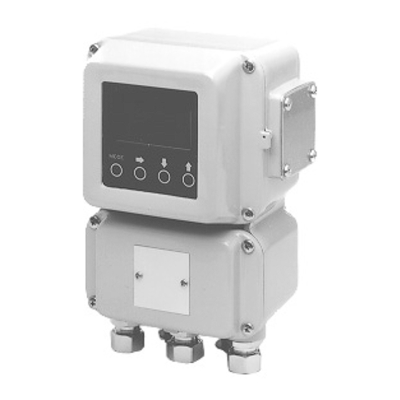
1.2 Structure of this Unit and Functions of Parts Structure of the Device This unit consists of the converter main body, the contact I/O card, pulse card, Main components data setting device, and a terminal box. Figure 1-6 Structure of the main body Contact input card Converter main body Data setting... - Page 23 Structure of the Device Continued The following table explains the various parts. Converter parts and explanation Name Explanation Converter main body • Converts signal electromotive force generated in the detector into the instantaneous flow rate. • Outputs the instantaneous flow rate to the control equipment as an analog or digital signal.
-
Page 24: Approval Of This Device
1-3. Approval of this Device Overview If 1/2 NPT wiring connection is selected, this device functions as an FM/CSA, non-incendive-approved model. In this case, the installation standards de- scribed in this section must be followed. Installation of this FM/CSA Nonincendive model device THIS EQUIPMENT IS SUITABLE FOR USE IN CLASS I, DIVISION 2, GROUPS(A, B, C, D), CLASS II/III, DIVISION 2, GROUPS (F, G), OR NON-HAZARDOUS LOCA-... - Page 25 1-12...
-
Page 26: Chapter 2 - Installing The Device
Chapter 2 - Installing the Device This chapter explains the installation and wiring procedures of the device in Outline of this chapter the following order. • Selecting the installation site • Adjusting the data setting device direction • Installing the device •... -
Page 27: Before Installation
2.1 Before Installation Selecting the Installation Site (1) In order to make full use of the device functions, please observe the following Introduction criteria when selecting an installation site. Notes : • Install the product in a location with an ambient temperature of -25°C - +60°C and an ambient humidity of 5 - 100% RH to prevent equipment malfunction or output errors. -
Page 28: Installation Method
2.2 Installation Method Installing the Converter Basic installation method There are three ways to install the converter: integral converters are as- Installation sembled with the detector; remote detectors can be wall mounted, or mounted on a 2B converters are assembled pipe. Figure 2-1 Wall-mounted Mounting plate... -
Page 29: Figure 2-3 Integral Assembly
Installing the Converter Continued Figure 2-3 Integral assembly Basic installation method Installation (continued) 2 - 4... -
Page 30: Electrical Wiring (1)
Electrical Wiring (1) A commercial power supply or DC 24 V ± 10% power supply is used. Introduction The following electrical wiring considerations are explained here. • Cable connection positions • Power supply and resistive load • Cable selection and installation •... -
Page 31: Electrical Wiring (2)
Electrical Wiring (1) Continued Terminal Figure 2-4 Terminal arrangement for remote converter arrangement 1-contact input and 1-contact output 2-contact input STATUS IN STATUS OUT STATUS IN1 STATUS IN2 – – – – POWER P.OUT I.OUT POWER P.OUT I.OUT – – –... -
Page 32: Electrical Wiring (3)
Electrical Wiring (1) Continued Remote converters Converter terminal tables 1-contact input and 1-contact output 2-contact input Symbol Meaning Symbol Meaning Flow rate Flow rate signal input signal input I.OUT Current output I.OUT Current output – – P.OUT Pulse output P.OUT Pulse output –... -
Page 33: Electrical Wiring (4)
Use a dedicated cable (Model: MGA12W) to connect the detector to the con- Cable between detector and verter. The signal cable used may be a dedicated cable made by Yamatake or converter a commercially available cable and depends on fluid conductivity, cable length, and the diameter of the detector. -
Page 34: Electrical Wiring (5)
Electrical Wiring (2) Continued Figure 2-6 Outer Dimensions of Signal Cables Signal Cables (Model: MGA 12W) Terminal treatment on detector side Terminal treatment on converter side For M4 screw For M4 screw Detector side Converter side For M4 screw Detector side (Model A) Detector side For M4 screw... -
Page 35: Electrical Wiring (6)
Electrical Wiring (2) Continued Figure 2-8 Outer Dimensions of Excitation Cables Excitation Cables (Model: MGA 12W) Insulating tube For M4 screw For M4 screw Detector side Converter side Terminal treatment on detector side For M4 screw Black Detector side White (Model A) For M4 screw Black... -
Page 36: Electrical Wiring (7)
Electrical Wiring (3) Figure 2-10 Detector-to-converter connection Detector-to-con- verter connection • Wiring of dedicated cables (Model: MGA12W) Signal cable Converter MGA12W Detector Excitation cable MGA12W • Commercially available cable Signal cable 2-core single-shielded cable Converter Detector Excitation cable 2 - 11... - Page 37 Electrical Wiring (4) The recommended wiring cable is a 600 V vinyl sheath electrical wire CVV Selecting the wiring cable (JIS C 3401) with a conductor section of 2 mm , or a twisted cable with an equivalent or higher capacity. Shielded wire is recommended for wiring at locations subject to electromag- netic noise interference.
-
Page 38: Figure 2-11 Wiring Diagram For Current Output
Electrical Wiring (5) The current output wiring method depends on whether or not communication Current output wiring with the S-SFC is used. An external power supply is required to communicate with the S-SFC. (Switch the main board pins after turning the power supply OFF.) Figure 2-11 Wiring diagram for current output •... -
Page 39: Figure 2-12 Wiring Diagram For Pulse Output
Electrical Wiring (6) The pulse output is an open collector output. Pulse output wiring Pay close attention to voltage and polarity when wiring. Figure 2-12 Wiring diagram for pulse output Protective diode 200mA max. Load this is impossible External power supply 30V max. -
Page 40: Figure 2-13 Wiring Diagram For Contact Input
Electrical Wiring (7) Either a semiconductive contact or a no-voltage contact can be used as the Contact input wiring contact input. The contact input/output terminals are not available when a 2-contact output model has been selected. Figure 2-13 Wiring diagram for contact input •... - Page 41 MEMO 2 - 16...
-
Page 42: Chapter 3 - Operating And Stopping Of The Measuring System
Chapter 3 - Operating and Stopping of the Measuring System This chapter explains the procedures for starting up this product and making Outline of this chapter zero adjustment. It also describes stopping the system. When starting up and operating this product for the first time, carefully follow the explanation given in this chapter. -
Page 43: Start-Up
3.1 Start-up Starting up Start up the electromagnetic flowmeter according to the following steps. Procedures Procedure Step Make sure the electromagnetic flowmeter detector is prop- erly installed on the pipe. Make sure the wiring between the electromagnetic flowmeter detector and converter has been completed properly. For communication with the S-SFC, make sure the S-SFC wiring has also been properly completed. -
Page 44: Preparations Before Measurement
3.2 Preparations before Measurement Zero Adjustment After start-up, be sure to zero the electromagnetic flowmeter. There are two Introduction zero adjustment methods: • Using the data setting device for this product • Using the S-SFC (Refer to S-SFC User's Manual CM2-MGG000-2001 For electromagnetic flowmeters without the data setting device, select the S-SFC method. -
Page 45: Method Using The Data Setting Device
Method Using the Data Setting Device Adjust the electromagnetic flowmeter so that the instantaneous flow when the Introduction fluid in the detector stands still is measured as zero. Notes: • Zero adjustment is very important for accurate flow rate measure- ment. - Page 46 Method Using the Data Setting Device Continued Method using the Step Procedure Screen data setting device Touch the key to start (continued) zero adjustment. During ad- justment, when the large 7- AUTO ZERO segment displays the flow rate in %, "0.0" will be flash- ing.
-
Page 47: Method Using The S-Sfc
Method using the S-SFC Method using the Perform the following steps. S-SFC S-SFC screen Step Procedure English Japanese Make sure the fluid to be mea- sured has been charged and is standing still in the detector. Make sure the S-SFC has MAG XXXXXXXX started up and is ready to c o m m u n i c a t e w i t h t h e... -
Page 48: Stopping
3.3 Stopping Caution • Before stopping the flowmeter operation and shutting off the output to the control equipment, be sure to switch the control equipment to manual control. This will prevent the power shut-off on this unit from directly affecting the control equipment. Perform the following steps to stop flowmeter operation. -
Page 49: Setting The Communication Function
3.4 Setting the Communication Function Configuration via communications requires changing the converter mode. Introduction To communicate with the device, set the switches as follows. Procedure 1 Step Procedure The main card will be visible. Set the SFC and I switches on the upper part of the card as shown below. - Page 50 3.4 Setting the Communication Function Continued When not using communications, set the switches as followings. Procedure 2 Step Procedure Remove the display cover. Set the SFC and I switches on the top of the main card as shown below. (Move the switches to the blackened posi- tions.) 3 - 9...
-
Page 51: Setting Write Protection
3.5 Setting Write Protection This product is set up at shipment so that settings can be made in any mode. Introduction However, write protection can be set to protect data from being accidentally changed after start-up. The following write-protect levels are available. The product is set to level 0 Levels of write protect when shipped. -
Page 52: Setting The Empty Detection Function
3.6 Setting the Empty Detection Function This function fixes the output at 4 mA and latches the display to zero when the Introduction detector becomes empty. To set the empty detection function, set the switches in the following steps. Procedures Step Procedure Remove the display cover. - Page 53 MEMO 3 - 12...
-
Page 54: Chapter 4 - Operation Using The Data Setting Device
Chapter 4 - Operation Using the Data Setting Device This chapter explains how to operate this product using the data setting de- Outline of this chapter vice. Read this chapter only if this device has a data setting device. Refer to the S- SFC user’s manual CM2-MGG000-2001 “Device Smart Electromagnetic Flowmeter S-SFC II User’s Manual”... -
Page 55: Functions Of The Data Setting Device
4.1 Functions of the Data Setting Device Data Setting Device Figure 4-1 shows describes the parts of the data setting device. Names of parts Figure 4-1 Names of data setter parts Main display Total display mark Percent flow rate display mark Actual flow rate display mark Infrared touch sensor... - Page 56 Data Setting Device Continued The following is an explanation of the various keys on the data setting device. Part names and explanation • When operating the keys, be sure to close the cover. Only touch the keys through the glass. •...
- Page 57 Data Setting Device Continued Part names and Name Explanation explanation (continued) Up key • Change the parameter at the cursor position. • Display the next screen. When the cursor is located at the far left of the upper row (*, #, >) Changes the O P E R A T O R ' S screen.
-
Page 58: Operating The Display/Data Setting Device
Operating the Display/Data Setting Device Outline of the The following 4 modes are available on the device. various modes Mode Explanation This mode indicates the measuring status. MEASURING MODE The operator setting mode is used for data that are OPERATOR'S MODE registered or changed frequently. - Page 59 Operating the Display/Data Setting Device Continued Outline of the Mode Explanation various modes (continued) This is the engineering setting mode. It is used for ENGINEERING MODE data that are registered or changed less frequently than in the Operator’s Mode. Settings can be registered or changed when write protect is set to level 0 or 1.
-
Page 60: Screen Organization
Screen Organization The device modes are arranged as follows. Introduction Operation at start-up LCD indication flow Flash Maintenance Mode 2 seconds later Example of measuring status Operator’s Mode 2 seconds later Engineering setting mode (*1) Indicates when there is a pulse circuit and “TOTAL” display is selected. (Continued on next page) 4 - 7... - Page 61 Screen Organization Continued Introduction Engineering setting mode (continued) 3 seconds (*2) Indicated when single range is selected. later (*3) Indicated when normal direction automatic double range or normal direction external switching range is selected. (*4) Indicated when normal/reverse automatic range or normal/re- verse external switching range is selected.
- Page 62 Screen Organization Continued Introduction (continued) Double range Single range (*8) Indicated when there is a pulse circuit. (*9) Indicated when there is a pulse circuit, and normal direction double range or normal/reverse direction range is selected. (*10) Indicated when high/low limit alarms are set for the contact out- put in function setting.
-
Page 63: How To Skillfully Operate The Touch Key Switches
How to Skillfully Operate the Touch Key Switches 1. As illustrated, move your finger upward from underneath the target, and completely cover the white round target. Then, move the finger downward to its original position. These motions ensure smooth key operation. If you move your finger side- ways, you may inadvertently actuate the wrong key. -
Page 64: How To Enter The Operator's Mode
How to Enter the Operator's Mode Step Procedure Screen The screen at right shows an example of display of 10 m3/h, 100% in the Measuring Mode. 10.00 m 3/h Touch the MODE key for 000032542 TOTAL about 3 seconds. Complete the following opera- tions within 8 seconds (the screen at right will be displayed ENTER IN OP. -
Page 65: Operating In Operator's Mode
Operating in Operator’s Mode The Operator’s Mode includes the following settings and adjustments. Introduction To enter the Operator’s Mode, touch the MODE key for more than three sec- onds. Screen display Description Indicated conditions Sets the damping time con- DAMPING stant AUTO ZERO Performs zero adjustment... -
Page 66: Resetting The Damping Time Constant
Resetting the Damping Time Constant Set a damping time constant to cut out minute fluctuations when transmitting Introduction the measured instantaneous flow rate to the control equipment. Check the amplitude of variation in instantaneous flow output and set the damping time constant to an appropriate value. -
Page 67: Zero Adjustment
Zero Adjustment Adjust the flowmeter so that the measured instantaneous flow rate will be zero Introduction when the fluid stands still in the detector. Notes: • Zero adjustment is very important for accurate flow measurement. Before operating the unit for the first time, be sure to zero the flowmeter. - Page 68 Zero Adjustment Continued Zero Adjustment Step Procedure Screen Continued Touch the key to start zero adjustment. When the large 7- segment display shows the AUTO ZERO flow rate in percent, “0.0” will flash during adjustment. When zero adjustment is completed, the flashing will stop and the “ON”...
-
Page 69: Setting The Reset Value Of The Built-In Flow Counter
Setting the Reset Value of the Built-in Flow Counter This sets and changes the integration starting value of the built-in flow Introduction counter. This function is used when a pulse output board has been selected (additional specification). The reset value is set to “0000000000” at shipment. Default setting Setting range –999999999 - 9999999999... -
Page 70: Resetting The Built-In Flow Counter
Resetting the Built-in Flow Counter This resets the current integrated flow rate and saves it to memory. Introduction The built-in counter indicates “0000000000” at power-up. This function is used when a pulse output board has been selected (additional specification). Step Procedure Screen Open the built-in counter reset... -
Page 71: Setting/Changing The Preset Value Of The Built-In Flow Counter
Setting/Changing the Preset Value of the Built-in Flow Counter This changes the contact output status from H to L or from L to H when the Introduction flow counter reaches a preset value. This function is used when contact output has been selected (additional speci- fication) and pulse output has been selected (additional specification). -
Page 72: Setting/Changing The Flow Rate Indication
Setting/Changing the Flow Rate Indication Selects the mode of flow rate indication for the main display: from percent Introduction display: actual flow rate display, and integrated value display. The default setting is percent display. Default setting Select either “%” (instantaneous percent flow rate), “RATE” (instantaneous Setting range actual flow rate), or “TOTAL”... -
Page 73: Selecting Modes
Selecting Modes Select either the Engineering Mode (to operate the setting parameters of the Introduction electromagnetic flowmeter) or the Maintenance Mode (to perform adjust- ments or inspection). Note: • In some cases, a mode selection screen will not open, depending on the write-protect setting. - Page 74 Selecting Modes Continued To enter the Maintenance Mode Introduction (continued) Step Procedure Screen Call up the Maintenance Mode selection screen by following the steps to enter the Operator’s MODE ENTER Mode. ENGINEERING Touch the key once. MODE ENTER MAINTENANCE Touch the key once.
-
Page 75: Engineering Mode
Engineering Mode The Engineering Mode contains the following settings and adjustments. Introduction Screen display Description Indicated conditions Sets the ID ID SET Sets the functions FUNC SET Sets detector data EX, TYPE, DIA Sets the number of dummy Selection of an NNK detec- DUMMY detectors tor in the detector data set-... - Page 76 Engineering Mode Continued Introduction Screen display Description Indicated conditions (continued) Sets high/low limit alarms Selection of alarm output HI-ALM/LO-ALM and high/low limit alarms in function setting (option). Sets the 2-stage low limit Selection of 2-stage low LO-ALM1/LO-ALM2 alarm alarm in function setting (option).
-
Page 77: Setting The Id
Setting the ID Sets the ID code for the electromagnetic flowmeter. Introduction Default setting XXXXXXXX The ID code can be set using up to 8 alphanumeric characters: letters (A to Z), Setting range numbers to 9), –, /, space, and period. Step Procedure Screen... -
Page 78: Selecting Functions
Selecting Functions Sets the electromagnetic flowmeter functions: range, counter, contact input, Introduction and contact output. There will be restrictions on the functions that can be set depending on your model's specifications. Note that the setting range will be limited depending on whether or not a pulse output board is used and the kind of contact input/ output boards. - Page 79 Selecting Functions Continued Introduction Step Procedure Screen (continued) Four touches of the key in Step 1 enables the selection of the contact output function. # FUNC SET F0A14 Touch the key to select ERROR DIAG ALM the desired function. When completing the settings of the respective functions, touch the key to move the...
-
Page 80: Relations For Setting Function Fxxxx
Relations for Setting Function FXXXX The range, built-in counter, contact input, and contact output functions can be Introduction set using the combinations shown in the table below. For example, when “Single range” and “Addition with preset” are selected, there are three contact input choices (X, 1, and 2) and three contact output choices. - Page 81 Relations for Setting Function FXXXX Continued 1-contact input and 1-contact output (DI/DO) Introduction (continued) (continued) Range function Built-in counter function Contact input function Contact output function 1: Automatic X: Not activated X: Not activated 2: Range switching output switching 1: External 0% lock 2: Range switching output double range 2: External auto zero adjustment 2: Range switching output...
- Page 82 Relations for Setting Function FXXXX Continued 2-contact input (DI/DI) Introduction (continued) Contact output Range function Built-in counter function Contact input function function 0: Single range X: Not activated X: Not activated X: Not activated 1: External 0% lock X: Not activated 2: External auto zero function X: Not activated 5: External 0% lock+Auto zero adjustment X: Not activated...
- Page 83 Relations for Setting Function FXXXX Continued 2-contact output (DO/DO) Introduction (continued) Built-in counter function Contact input Range function Contact output function function 0: Single range X: Not activated X: Not activated X: Not activated 1: Alarm output 4: Self-check result output 5: Empty detection function 6: High/low limit alarm A: Addition...
-
Page 84: Range Functions
Range Functions Measures a single range in the normal direction. Single range The output for a reverse flow will be as follows. Analog output: Possible to approx. -20% (0.8 mA). With S-SFC communica- tion, to approx. -5% (3.2 mA). Pulse output: No output Display: A minus (–) symbol appears. -
Page 85: Figure 4-2 Normal Direction Automatic Double Range
Range Functions Continued This function has two ranges: wide and narrow. When the narrow range mea- Normal direction automatic double surement exceeds 100%, the unit automatically changes to the wide range. range This function should be used in combination with the wide/narrow range dis- tinction output contact. - Page 86 Range Functions Continued The range is switched via an external switching command contact input. Normal direction, external switching Also, the wide/narrow range distinction contact output (status signal) can be double range sent out using the same timing. Analog output When AUTO is selected for an analog output Range No.1 4 - 20 mA DC Range No.2 4 - 20 mA DC When WIDE is selected for an analog output...
-
Page 87: Figure 4-3 Normal/Reverse Automatic Switching Range
Range Functions Continued Automatically switches the range when the fluid flow direction reverses. Normal/reverse automatic switching Hysteresis is available at the time of normal/reverse switching. range Analog output Normal direction: 4 - 20 mA DC Reverse direction: 4 - 20 mA DC When there is a pulse output There is no distinction in output between the normal and reverse direc- tions. - Page 88 Range Functions Continued Switches between the normal and reverse ranges by inputting a switching Normal/reverse external switching command contact from the gear section. range It is also possible to output the normal/reverse range distinctive contact output (status signal) using the same timing. Analog output When AUTO is selected for an analog output Normal direction: 4 - 20 mA DC...
-
Page 89: Built-In Counter Function
"Built-in Counter Function" X: Not activated (No pulse output) A: Addition counter In the normal/reverse range, addition is performed in the normal and re- verse directions, respectively. B: Addition counter with preset The preset value ranges from 0000000000 - 9999999999. In the normal/reverse range, addition is made in the normal and reverse directions, respectively. -
Page 90: Contact Input Function
"Contact Input Function" This function can be set when either 1- or 2-contact input has been selected in the additional specifications. X: Not activated 1: External 0% lock input Used to completely halt the flow rate signal (display, analog output, or pulse output) at 0%. -
Page 91: Contact Output Function
"Contact Output Function" This function can be set when 1- or 2-contact output has been selected in the additional specifications. X: Not activated 1: Alarm contact output An alarm is output when any of the following items becomes abnormal. The abnormal item can be checked on the display inside the instrument. Also, external confirmation is available using the S-SFC. - Page 92 "Contact Output Function" Continued Empty detection function When the detector becomes empty of the measured fluid, the respective output signals will be as follows. Status When the detector is empty of fluid Output signal Analog output 4 - 20 mA DC 4mA DC Pulse output Abnormal status (Open/closed can be freely...
- Page 93 "Contact Output Function" Continued A: High/low limit alarm and range switching output (2-contact output) The high/low limit alarm can be set to ST.OUT1 and the range switch- ing output to ST.OUT2. B: Range switching output and counter preset status output (2-contact out- put) The range switching output can be set to ST.OUT1 and the preset status output to ST.OUT2.
-
Page 94: Detector Data Setup
Detector Data Setup This is used to set and select the constant, model, and diameter of the detector Introduction to be used in combination with the converter. When there is no detector setting, EX300.0, MGG, DIA 050.0 will be se- Default setting lected. - Page 95 For models MGG and KID, input the value indicated on the nameplate into the converter. For models NNM and NNK, contact Yamatake Corporation sales per- sonnel when you need to change the setting. Missetting will cause errors and equipment damage.
-
Page 96: Setting The Number Of Dummy Detectors
Setting the Number of Dummy Detectors This is used to set the number of dummy detectors installed with the NNK Introduction detector (selected in the detector data setting) (page 4-37). This screen appears only for underwater electromagnetic flowmeter NNK. Default setting 0 - 9 Setting range Step... -
Page 97: Setting The Range
Setting the Range This is used to set the flow rate measurement range, which means the value Introduction when the electromagnetic output reaches 100%. The lower limit of the range is zero. Flow rate: 0.0001 - 99999 Setting the range Units: , l, cm , t, kg, g... -
Page 98: Setting Hysteresis
Setting Hysteresis This is used to set the hysteresis as a range function to be used at range switch- Introduction ing. Use for normal direction automatic double range or the normal/reverse direction automatic double range. Default setting 0 - 20% Setting range Step Procedure... -
Page 99: Selecting The Current Output Method
Selecting the Current Output Method This is used as a range function with the normal direction double range or Introduction normal/reverse direction double range, to select how to output the 4 - 20 mA analog output: with either the range switching method or the wider range method. -
Page 100: Setting The Specific Gravity
Setting the Specific Gravity This is used to set the specific gravity when selecting a weight unit (t, kg, g) in Introduction range setting. Without this setting, an output error may result. 1.0000 Default setting 0.1000 - 9.9999 Setting range Step Procedure Screen... -
Page 101: Setting/Changing The Coefficient Of Compensation
Setting/Changing the Coefficient of Compensation The coefficient of compensation can be set to multiply the output flow rate as Introduction required. 1.0000 Default setting 0.1000 - 9.9999 Setting range Step Procedure Screen Open the compensation coeffi- cient setup screen by following the steps to enter the Engineer- # COEFFICIENT ing Mode. -
Page 102: Setting The Pulse Scale
Setting the Pulse Scale The flow rate per pulse can be set when a pulse output board has been selected Introduction (additional specifications). This is used to set the pulse scale so that the fre- quency on the upper right of the 16-digit display will not exceed 2,000 Hz. When changing the pulse scale with a double range, use the wider range. -
Page 103: Setting The Pulse Width
Setting the Pulse Width The pulse width that will be output from the pulse output terminal can be set Introduction when a pulse output board has been selected. This is used to set the pulse width so that the duty ratio at the upper right of the 16-digit display will not exceed 70%. -
Page 104: Setting The Drop-Out
Setting the Drop-out A drop out is set to prevent incorrect integration of the flow rate. Pulse count- Introduction ing will pause when the flow rate is at the preset percentage of the set range. Default setting 0 - 10% Setting range Step Procedure... -
Page 105: Setting High And Low Limit Alarms
Setting High and Low Limit Alarms An alarm is output when the instantaneous percent flow rate exceeds the pre- Introduction set high and low limits. This function can be used when the high/low limit alarm is selected in the Important contact output function. -
Page 106: Setting A 2-Stage Flow Rate Alarm
Setting a 2-stage Flow Rate Alarm A first alarm will be output when the instantaneous percent flow rate exceeds Introduction the preset first high or low limit. A second alarm will be output when the flow rate exceeds the second high or low limits. This function can be used when the 2-stage high/low limit alarm is selected in Important the contact output function. - Page 107 Setting a 2-stage Flow Rate Alarm Continued Setting the flow rate Step Procedure Screen alarm (Continued) Touch the key to set the 2- stage high limit alarm in the same way. # HI-ALM1 -100 % HI-ALM2 -100 % Use the key to move the cursor to the desired digits.
-
Page 108: Setting The Low Flow Cut
Setting the Low Flow Cut When the fluid flow inside the detector is narrow, the fluid is regarded as Introduction stationary and the analog output can be latched to zero. The value at which to cut the flow in this situation is referred to as the "low flow latch." Default setting OFF or ON 0% - ON 10% Setting range... -
Page 109: Determining The Pulse Output Abnormality Treatment Direction
Determining the Pulse Output Abnormality Treatment Direction It is possible to determine the pulse output direction when an abnormality Introduction occurs in the electromagnetic flowmeter and flow rate measurement becomes impossible. Use this function when pulse output is selected. Caution •... -
Page 110: Determining Analog Output Abnormality Treatment Direction
Determining the Analog Output Abnormality Treatment Direction It is possible to determine the anal Introduction g output direc Caution • The abnormality treatment direction is very important for securing the safety of the overall control process. Determine the treatment direction very carefully. Otherwise the equipment will be dam- aged. -
Page 111: Setting The Contact Output Status
Setting the Contact Output Status This is used to set the contact output status for normal operation. Introduction Important This function is displayed when contact output has been selected (additional specification). "CLOSE" Default setting "CLOSE" "OPEN" Setting range For 1-contact input and 1-contact output Step Procedure Screen... - Page 112 Setting the Contact Output Status Continued <For 2-contact output> Setting range (continued) Step Procedure Screen Open the contact output status setup screen by following the steps to enter the Engineering # ST. OUT1 MODE Mode. NORMAL CLOSE Touch the key. # ST.
-
Page 113: Maintenance Mode
Maintenance Mode The Maintenance Mode includes the following adjustments and items to be Introduction checked. Refer to Chapter 6 for the operating method. OUTPUT CHECK Screen display Description Indication conditions MODE Checks the analog output loop OUTPUT CHECK I.OUT Checks the pulse output loop Selection of pulse output. - Page 114 MEMO 4 - 61...
-
Page 115: Chapter 5 - Maintenance And Troubleshooting Of The Electromagnetic Flowmeter
Chapter 5 - Maintenance and Troubleshooting of the Electromagnetic Flowmeter This chapter describes the maintenance and inspection procedures for the Outline of this chapter electromagnetic flowmeter and the information that should be referred to dur- ing troubleshooting. First, this chapter explains the procedures used to check the converter func- tions. -
Page 116: Checking Functions
5.1 Checking Functions Checking the Input/Output Signal Loop The converter includes a constant current generator. Current from 0% to Introduction 115% of the flow rate signal can be set. Loop checking can be performed with this function, as can loop checking of the pulse output and contact input/out- put. -
Page 117: Checking The Analog Output
Checking the Analog Output The analog output can be checked by using the electromagnetic flowmeter as Introduction a constant current generator. Display current output Default setting 000.0% - 115.0% (the percentage is the ratio of the preset range.) Setting range Step Procedure Screen... -
Page 118: Checking The Pulse Output
Checking the Pulse Output The pulse output can be checked by using the electromagnetic flowmeter as a Introduction constant current generator. This screen will appear if pulse output has been selected (additional specifica- tion). Display current output Default setting 000.0% - 115.0% Setting range Step Procedure... -
Page 119: Checking The Contact Input/Output Loop
Checking the Contact Input/Output Loop Check the contact input terminal status on the LCD by turning ON/OFF the Introduction contact input terminal of the electromagnetic flowmeter. It is also possible to check the loop of the contact output signal by turning ON/ OFF the contact output terminal of the electromagnetic flowmeter. - Page 120 Checking the Contact Input/Output Loop Continued When 2-contact input is selected Setting range (continued) Step Procedure Screen Open the contact input loop check screen by following the steps to enter the Maintenance > ST. IN1 CLOSE Mode. ST. IN2 CLOSE There is no cursor movement on this display.
-
Page 121: Checking The Excitation Current
Checking the Excitation Current It is possible to check the excitation current value that flows into the coil in the Introduction detector and its flow direction. This check is not possible for integral models. Step Procedure Screen Open the excitation current check screen by following the steps to enter the Maintenance >... -
Page 122: False Signal Input By Calibrator
False Signal Input by Calibrator The electromagnetic flowmeter is provided with a dedicated calibrator, which Introduction has the function of generating the same signal as the flow rate signal from the detector. The converter function can be checked using this false signal. When a problem occurs in the converter, use this method to judge whether When to use detector or the converter is responsible for the problem. -
Page 123: Troubleshooting
5-2 Troubleshooting Overview If a problem occurs at electromagnetic flowmeter start-up and operation, the Introduction following three causes should be considered. Inconsistency between the electromagnetic flowmeter’s specifications and the actual operating conditions Missetting or misoperation Electromagnetic flowmeter malfunction If a problem occurs during electromagnetic operation, the converter’s self- diagnostic function will classify it as serious or minor. -
Page 124: Errors At Start-Up
Errors at Start-up When a problem occurs at start-up, perform the following procedures. Troubleshooting If the problem remains, it is possible that the electromagnetic flowmeter has been damaged. Contact the reference listed on the last page of this manual. Trouble Check points and treatment No indication on display •... -
Page 125: Errors During Operation
Errors during Operation When a problem occurs during operation, perform the following procedures. Troubleshooting 1. Check against the table on this page for symptoms of the error. If found, perform the steps indicated in the table. 2. When communication with S-SFC is used, read the error message and the self-diagnostic result using the STAT (diagnosis) key. - Page 126 Errors during Operation Continued Troubleshooting Trouble Check points and treatment (continued) • Refer to “Error messages and treatment” to Output has burnt out. perform measures. Pulse output is too large or • Make sure the pulse scale and width are cor- too small for the flow rate.
- Page 127 Error Messages and Treatment (Display) Hardware check is executed in the Measuring Mode. Hardware check Perform the proper measures immediately. While an error code (Err-01 to Err-05) is being displayed, the output for the abnormal situation will be as preset in the Engineering Mode. Error codes for E r r - 01 serious trouble...
- Page 128 Error Messages and Treatment (Display) Continued Missetting diagnostics are executed in the Engineering Mode. Checking for mis- setting When a setting is incorrect, the error will be displayed for one second and then the incorrectly-set screen will appear. (To view the error contents again, press the MODE key.) Note: Press the MODE key for more than 5 seconds, and the data will return to the status obtaining before entering the Engineering Mode.
- Page 129 Parts List Continued MGG10C MGG14C 6 - 1...
- Page 130 Parts List Continued MGG10C / 14C Key No. Description Quantity Part No. Converter main body (Standard finish) 80381001-001 (Corrosion-resistant finish) 80381001-101 (Corrosion-proof finish) 80381001-201 Contact input/output card (2 inputs) 80381221-001 (1 input / 1 output) 80381221-002 (2 outputs) 80381221-003 Main card 80381035-001 Displaycontrol card / pulse card (W / pulse)
- Page 131 Parts List Continued MGG10C / 14C Key No. Description Quantity Part No. Tag No. plate (W / Tag No.) 80381014-001 Screw HS311230-050 Terminal box cover (Standard finish) 80381010-001 (Corrosion-resistant finish) 80381010-101 (Corrosion-proof finish) 80381010-201 Watertight gland (Ni plated brass) 80356020-101 (Plastic) 80352997-001 (SUS304)
- Page 132 Parts List Continued MGG10C / 14C Key No. Description Quantity Part No. Power unit (AC100V) 80381220-101 (AC110V) 80381220-102 (AC120V) 80381220-103 (AV200V) 80381220-201 (AC220V) 80381220-202 (AC240V) 80381220-203 (DC24V / 50Hz) 80381220-301 (DC24V / 60Hz) 80381220-302 Adaptor assembly (1/2NPT) 80381077-001 (CM20) 80381077-002 (Pg13.5) 80381077-003 6 - 4...
- Page 133 Document Number : CM2-MGG210-2001 Document Name : MagneW3000 PLUS Smart Electromagnetic Flowmeter General Use Converter Model MGG14C Date : Mar., 1997 Aug., 2004 (Rev. 5) Issued / Edited by : Yamatake Corporation...
- Page 134 Savemation Saving through Automation 2-12-19 Shibuya Shibuya-ku, Tokyo 150-8316 Japan Tel : 81-3-3486-2310 Fax : 81-3-3486-2593 http://www.yamatake.com/ This has been printed on recycled paper.
Need help?
Do you have a question about the MagneW3000 PLUS and is the answer not in the manual?
Questions and answers