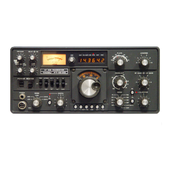
Sign In
Upload
Manuals
Brands
Yaesu Manuals
Transceiver
FT-101ZD
Yaesu FT-101ZD Manuals
Manuals and User Guides for Yaesu FT-101ZD. We have
6
Yaesu FT-101ZD manuals available for free PDF download: Service Manual, Instruction Manual, User Manual
Yaesu FT-101ZD Service Manual (194 pages)
Brand:
Yaesu
| Category:
Transceiver
| Size: 20.64 MB
Table of Contents
Index
2
General Information: Table of Contents
4
Transceiver View
5
General Description
5
Specifications
6
FT-101ZD Series Model Chart
7
Recommended Accessories
8
FV-901DM Synthesized, Scanning Remote VFO
8
FTV-901 Vhf/Uhf/Oscar Transverter
8
YO-901 Multiscope
9
SP-901P Speaker/Hybrid Phone Patch
9
FC-901 Antenna Coupler
9
Controls and Switches
10
Key/MIC/Acc Plugs Diagrams
12
VFO Plug Diagram
12
Pin Plug Diagram
12
Headphone and External Speaker Plugs Diagrams
12
Rear Apron View and Description
13
Accessories
14
Microphone Connections Views and Diagrams
15
Interconnections Diagrams
16
Interconnections Diagrams (Cont)
17
Installation
18
Preliminary Inspection
18
Base Station Installation
18
Mobile Installation
19
Antenna Considerations
19
Operation
20
Initial Check
20
Receive Operation
20
Transmitter Tuning
21
Loading Positions
21
Final Tuning
21
SSB Operation
22
RF Speech Processor Adjustment
22
CW Operation
22
AM Operation (with Optional am Unit) (after Prod. #8)
23
FM Operation (with Optional FM Unit) (after Prod. #8)
23
Select Switches
23
Dial Calibration and Frequency Determination
23
Fixed Channel Crystal Information
24
Tecnhical Notes: Table of Contents
25
Part Designations on Circuit Boards
26
FT-101Z Circuit Boards
26
Signal Tracing in the FT-101ZD
26
SSB/CW Mode RX FT-101ZD Block Diagram
27
SSB Mode TX FT-101ZD Block Diagram
28
CW Mode TX FT-101ZD Block Diagram
29
AM Mode RX FT-101ZD Block Diagram
30
AM Mode TX FT-101ZD Block Diagram
31
Frequency Relationships Diagram
32
Crystal Data FT-101ZD Table
32
Circuit Description
33
Receiver
33
FT Unit (PB-1960) Early Model (before Prod. #17)
33
IF Unit (PB-1963)
33
SSB, CW Filters/Width Filter Diagram
34
Width Control Action Diagram
34
NB-FIX Unit (PB-1961)
36
AF Unit (PB-1964)
36
Marker Generator
36
Transmit Circuit
38
SSB Mode/Af Unit (PB-1964)
38
RF Unit (PB-1960)/Drive Unit (PB-1714), PA Unit (PB-1715)
38
CW Mode/Drive Unit (PB-1714), PA Unit (PB-1715)
38
VOX Circuit
39
CW Sidetone/Am Mode
39
Common Circuits
39
VFO Unit (PB-1440B-3420)
39
NB and Fix Unit (PB-1961)
40
Premix Local Unit (PB-1711) (before Prod. #17)
40
Premix Unit (PB-1962) (before Prod. #17)
40
Counter Unit (PB-1978, PB-1979, PB-1980) (before Prod. #16)
41
Power Supply
43
Servicing: Table of Contents
44
Outer Cover Removal
46
Front Panel Removal
47
Board Layout (Early Model, before Prod. #15)
48
Pilot Light Replacement
49
Counter Preset Switch Replacement
49
CW Filter Installation
50
Counter Unit Installation on FT-101Z
51
FT-101Z/ZD Aux Band Installation
52
Parts Needed
52
Modification Procedure
52
Alignment after Modification
52
Example for 2.0-2.5 Mhz Wiring
53
FT101Z Aux Band Table
54
DC-DC Converter Installation
55
Notes on Mobile Installation
55
Cooling Fan Installation
56
DC-DC Converter Exploded View
56
Cooling Fan Installation (Option)
56
DC-DC Converter (Exploded View)
56
Soldering and Desoldering Technique on Printed Circuit Boards
57
Notes on Use of CMOS IC's
57
Insertion of Parts on Circuit Boards
57
Basic Soldering Practice
58
Soldering to Terminal Posts
58
Examples of Poor Soldering Practice
58
Circuit Trace Repair
59
Modifications
61
Modification of FV-901DM for Use with FT-101ZD
61
Before/After Modification Diagrams
62
Rectifier B Unit Modifications
63
Rectifier B Unit Parts Layout
64
Low-Pass Filter Addition
65
VOX Circuit Modification
66
Counter Circuit Modifications
67
VFO Drift in Conjunction with Dimmer Control
68
21.2 Mhz Spurious Suppression on FT-101Z (Analog Dial)
69
AF Unit Capacitor Polarity Check
70
Maintenance and Alignment
71
AF Unit Alighment
71
VOX Circuit: Antitrip Level Setting
71
VOX Relay Delay Setting
71
CW Sidetone
72
Marker Frequency Setting
72
Carrier Frequency Adjustment
72
SSB Carrier Point
72
Carrier Balance
73
CW Carrier Point
73
IF Unit Alignment
74
Recrifier B Unit
74
Bias Adjustment
74
Variable if Bandwidth Alignment/Alc Meter Alignment
74
VFO Unit
75
Premix Local Unit/Premix Local Alignment
75
NB-Fix Unit
75
Fixed Channel Frequency Alignment
75
NB-FIX Unit (PB-1961) View
76
Premix Local (XTAL) Unit (PB-1965) View
76
Premix Unit (PB-1962) View
76
AM Unit (after Production Lot #8)
77
Transmit RF/IF Transfotmer Alignment
77
Receiver RF/IF/NB Transformer Alignment
77
AM Unit (PB-2040) View
77
Alignment of Transmitter Mixer/Driver and Receiver Front End Stages
78
RF Unit (PB-1960) View
78
Advice on Troubleshootiing the Driver/Final Amplifier Stages
80
Final Amplifier Neutralization
80
Rect a Unit (PB-1967) View
80
Final Amplifier Compartment View
80
Clarifier Alignment
81
Counter Unit
81
Frequency Counter Preset Switch Position Diagram
81
Fault Localization
82
10 Pin Extended Board View
82
14 Pin Extended Board View
82
Troubleshooting: a Fundamental Analysis of the Trouble
83
Typical Part Failures, Causes and Symptoms
84
Receive Mode: Troubleshooting Chart
85
Transmitter: Troubleshooting Chart
88
Common Circuits: Troubleshooting Chart
90
Relay Connection Information
92
RF Unit (PB-1960A) (Early Model) before Prod. #16 Schematics
93
DC Voltages Table
93
RF Unit Parts Layout
94
Nb/Fix Unit (PB1961B) Schematics/DC Voltages Tables
95
Nb/Fix Unit Parts Layout
96
Premix Unit (PB1962A) (Early Model) before Prod. #16 Schematics
97
Premix Unit Parts Layout
98
IF Unit (PB-1963C) Schematics
99
IF Unit Voltage Charts
100
IF Unit Parts Layout (1)
101
IF Unit Parts Layout (2)
102
AF Unit (PB-1964) Schematics
103
AF Unit Voltage Charts
104
AF Unit Parts Layout (1)
105
AF Unit Parts Layout (2)
106
Premix Local Unit (PB1965) (Prod. #01~#16) Schematics
107
Premix Local Unit (PB1965) DC Voltages
107
Premix Local Unit Parts Layout
108
VFO Assembly VFO Board (PB-1440B-3420) Schematics
109
VFO Assembly Parts Layout
110
VFO Unit Exploded View
110
Rect a Unit (High/Low Voltages) Unit (PB-1967) Schematics
111
Capacitor Unit (PB-1969A) Schematics
112
Rect B (Medium/Bias Voltages) Unit (PB-1968B) Schematics
113
Rect B (Medium/Bias Voltages) Unit (PB-1968B) DC Voltages Chart
113
Rect B Unit Parts Layout
114
Trimmer a Board (PB-1970A) Schematics
115
Trimmer a Board (PB-1970B) Schematics
115
Trimmer C Board (PB-1092) Schematics
116
LED Unit (PB-1974A) Select Switch Unit (PB-1966C) Schematics
117
Band Width Control Unit (PB-1972) Schematics
118
Clarifier Unit (PB-1973)
118
Lever Switch Unit (PB-1975A) Schematics
119
Counter Unit Parts Layout
121
Removal of Counter and Display Units
122
Driver Board (PB-1714A) Layout
124
Final Board (PB-1715A) Layout
124
AM Unit (PB-2040) Schematics
125
AM Unit (PB-2040) DC Voltages Chart
125
AM Unit Parts Layout
126
Repair Parts: Table of Contents
128
Parts List and Ordering Forms
129
Parts List
133
Late Model Update: Table of Contents
147
High-Performance HF Transceiver Yaesu FT-101ZD View and General Description
148
High-Performance HF Transceiver Yaesu FT-101ZD Controls and Switches
149
High-Performance HF Transceiver Yaesu FT-101ZD Plugs Views
151
High-Performance HF Transceiver Yaesu FT-101ZD Rear Apron
152
High-Performance HF Transceiver Yaesu FT-101ZD Accessories
153
High-Performance HF Transceiver Yaesu FT-101ZD Block Diagram
154
High-Performance HF Transceiver Yaesu FT-101ZD Receiver: Circuit Description
155
FM Unit (PB-2219) Option
156
APF Unit (PB-2217)
157
RF Unit (PB-2154)/FM Mode
158
High-Performance HF Transceiver Yaesu FT-101ZD Common Circuits: Premix Local Unit (PB-2153)
159
Premix Local (XTAL) Unit (PB-2153)
159
Premix Unit (PB-2152)
160
Counter Unit (PB-2086A-3420/PB-2098)
161
Counter Unit (PB-2086A) View
162
High-Performance HF Transceiver Yaesu FT-101ZD: Maintenance and Aligmnent/Premix Local Alignment
164
Premix Local (XTAL) Unit (PB-2153) Diagram
164
Premix Unit (PB-2152) Diagram
165
High-Performance HF Transceiver Yaesu FT-101ZD Adjustments (Cont)
166
Optional Installations
167
FT-101ZD DC-DC Converter Installation
167
Counter Unit (PB-2086A) Installation on FT-101Z
169
FM Unit Installation
170
AM Unit Installation
171
List of Parts
172
FT-101ZD Circuit Diagram
190
Advertisement
Yaesu FT-101ZD Instruction Manual (64 pages)
Brand:
Yaesu
| Category:
Transceiver
| Size: 57.05 MB
Table of Contents
General Description
3
Specifications
4
Controls and Switches
6
Rear Apron
9
Preliminary Inspection
12
Base Station Installation
12
Mobile Installation
13
Antenna Considerations
13
Initial Check
14
Frequency Selection
14
Receive Operation
14
Transmitter Tuning
14
Final Tuning
15
Ssb Operation
15
Parts Needed
22
Circuit Description
24
Tran Smit Circuit
29
Ssb Mode
29
Drive Unit
29
Power Supply
34
Top View
35
M Aintenance and al I G Nment
36
Equipment Required
36
Counter Unit
43
Yaesu FT-101ZD Instruction Manual (62 pages)
high-performance hf transceiver
Brand:
Yaesu
| Category:
Transceiver
| Size: 23.22 MB
Advertisement
Yaesu FT-101ZD User Manual (60 pages)
high-performance
Brand:
Yaesu
| Category:
Transceiver
| Size: 3.04 MB
Yaesu FT-101ZD Instruction Manual (59 pages)
Brand:
Yaesu
| Category:
Transceiver
| Size: 7.87 MB
Yaesu FT-101ZD Instruction Manual (36 pages)
communications receiver
Brand:
Yaesu
| Category:
Receiver
| Size: 3.64 MB
Advertisement
Related Products
Yaesu FT-101E
Yaesu FT-101EE
Yaesu FT-101
Yaesu FT-101B
Yaesu FT-101EX
YAESU FT-1000
YAESU FT-102
Yaesu FT-100D
Yaesu FT-10R
Yaesu FT-107M
Yaesu Categories
Transceiver
Radio
Receiver
Two-Way Radio
Repeater
More Yaesu Manuals
Login
Sign In
OR
Sign in with Facebook
Sign in with Google
Upload manual
Upload from disk
Upload from URL