Yaesu FT-101ZD Instruction Manual
Hide thumbs
Also See for FT-101ZD:
- Service manual (194 pages) ,
- Instruction manual (62 pages) ,
- User manual (60 pages)
Table of Contents
Advertisement
Advertisement
Table of Contents

Related Manuals for Yaesu FT-101ZD


Summary of Contents for Yaesu FT-101ZD
- Page 2 TABLE CONTENTS (Page) GENERAL DESCRIPTION SPECI FICATIONS TUB ES AND S EM ICONDUCTO RS CONTROLS AND SWITCHE S REAR APRON C ONNECTIONS ACCESSORIE S INSTALLATION · · · · · · · · · OPERATION · · · 2 1 BLOCK DIAGRAM ·...
-
Page 3: General Description
. mum satisfaction from your new Y AESU trans And Yaesu designers have now made it possible ceiver. for you to s witch sidebands without recalibrating the display . -
Page 4: Specifications
SPECIFICATIONS Frequency coverage: Transmitter frequen cy stability: 1 60 m 1 . 8 - 2 . 0 MHz Less than 3 0 0 Hz after 1 0 minute warmup; less than 1 00 Hz after 30 minute warmup . 80 m 3 . - Page 5 3 SK40M 1 S l 5 5 5 3 SK5 1 -0 3 1 00 1 1:3 1 0 l OD l O V06B FT-101ZD SERIES MODEL CHART 0 =BUILT-IN FEATURE X =AVAILABLE OPTION FEATURE FT-101 ZD FT-101Z ALL BAND CRYSTALS...
-
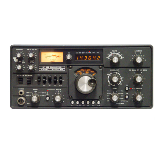
Page 6: Controls And Switches
CONTROLS AND SWITCHES VFO ..This swit ch selects control o f the ( 1 ) MODE transceive frequency on the FT- 1 0 I ZD Selection of LSB, USB, CW-W (SSB filter) , and internal VFO . - Page 7 ( 20 ) DELAY ( 1 0 ) AF GAIN This control sets the delay time for the VO X relay. The AF GAIN control varies the output level of For voice-actuated S SB , or semi-break-in CW, the the audio amplifier stages . Clockwise rotation operator may select the delay time most suitable increases the audio output level .
- Page 8 ( 26 ) POWER This is the main ON/OFF swit ch for the trans ceiver. (27) HEATER With the HEATER switch on, heater voltage is applied to the driver and final amplifier tubes. This switch m ay be turned off during periods of RX , when energy conservation is criti cal .
-
Page 9: Rear Apron
REAR APRON ® CV®®®@@ (1) RF TONE OUT RF output of 3 volts RMS is available at this jack The CW sidetone may be fed to an external re ceiver for use with a transverter. Output is from the through this j ack . driver stage . - Page 10 ( 1 7) PATCH ( 1 3 ) POWER Microphone or phone patch input may be m ade at Connect the AC power cord at this point , being cert ain that your AC supply volt age mat ches the this jack.
- Page 11 INTERCONNECTIONS TELEPHONE LINE FL-2100F FT-101ZD RF OUT --r;:r- FV-901DM � PIN6 ANTENNA · FT-101 ZD/FV-901 DM/FL-21 OOF/SP-901 P ANTENNA EXT RECEIVER ANTENNA JACK FTV-901R FT-101ZD EXT RCV :::: ::Q:l l=> H F ANT FT-101 ZD/FTV-901 R - 9 -...
-
Page 12: Preliminary Inspection
INSTALLATION BASE STATION INSTALLATION The FT- 1 0 1 Z D is designed to be a single-unit station for fixed or portable operation from AC The FT- l O l Z D is designed for use in many areas power. Power supply connections providing for of the world , using supply voltages that may differ operation from a variety of source voltages are from your local supply voltage . -
Page 13: Mobile Installation
RED lead is conne cted to the chassis at the antenna mount . See your Yaesu POS ITIVE battery terminal , and the BLACK lead is conne cted to the NEGATIVE battery terminal . -
Page 14: Initial Check
OPERATION The tuning pro cedure for this transceiver is not ( 3 ) The RX CLARIFIER may be utilized if the complicated. However, care should be exercised received signal is drifting. Push the RX but when tuning so that peak perform ance of the ton , and rotate the CLARIF IER control for o ffset of up t o 2 . -
Page 15: Final Tuning
Do not e x ceed 1 0 seconds of key-down time while FINAL TUNING tuning. Final transmitter tuning uses the relative power output setting o f the M ETER swit ch. At full rated As well , be certain that the ACC plug is inserted output , using a 50 ohm load , the PO m eter will into the rear apron ACC jack . - Page 16 Note : When the METE R swit ch is set to IC, voice C W OPERATION modulation peaks will indicate 1 5 0 - 200 After completing the tuning procedure , insert the mA. Actual peak current , though, is ap key line into the KEY j ack on the rear panel .
- Page 17 . Be careful so as not to operate outside the amateur bands. When u sing the FV-90 1 DM synthesized, scanning external VFO, available from your Yaesu dealer, your FT-l O l Z D will have available a 40-frequen cy memory bank, as well as a three-speed scanner.
- Page 18 6 9 9 9 .2 1 6 0 m 10 1 ZD, using optional crystals. Crystals available from your Yaesu dealer. Cryst als must 8 0 m 8 99 8.5 9 0 0 1 . 5 8 9 9 9. 2...
- Page 19 ( 4 ) Install t h e optional C W filter a s shown i n the CW FILTER INSTALLATION ( OPTION ) foil side vie w o f the IF unit (Fig. 3 ) . Make the ( 1 ) fastening nuts snug , and solder the pins of the Rem ove the top cover o f the transceiver case , filter to the circuit b oard , and remove the 2...
- Page 20 DC-DC CONVERTER INSTALLATION should b e volts or less. If the voltage is (OPTION) higher than this level, please adjust the voltage regulator for a maximum o f volts. This The optional DC-DC converter is easy to install in pre cautio n applies, as well, to bench power a matter of minutes.
- Page 21 C OOLING FAN INSTALLATION (OPTION ) The FT- 1 0 1 Z D cooling fan may b e used with other models o f Yaesu equipment . Installation is easily a ccomplished in minutes. Hold the fan up to the rear panel in its proper location .
-
Page 22: Parts Needed
"G" so cket on the transceiver at point in the COUNTER UNIT INSTALLATION ON FT- l O l Z drawing. coaxial cable from COUNTE R UNIT is connected to point "F" This se ction will deal with the installation o f the COUNTER UNIT and digital display , which are in Figure l . - Page 23 ----- iF u --- T ,..- - - ---- A F UNIT Cf. 8988.3kHz ��:5�� AN T XF402 0407 0406 600Hz 2SA564A 2SK19BL PRO OFF ALC METER ALC METER PROC 1- - - - PROC ON Vl601 V1701 0403 0105 106 1 2 BY7A TA7060P...
-
Page 24: Circuit Description
CIRCUIT DESCRIPTION The block diagram and following circuit descrip UNIT (PB- 1 96 0) tion will provide you with a better underst anding of the design of this transceiver. The circuit The incoming signal is amplified by the RF description is tailored to the full-feature FT- amplifier, Q 1 0 1 a dual-gate M OSFET ( 3 SK5 1 -03 ) ,... - Page 25 For use with the FV-90 1 DM scanning VFO, or IF UNIT (PB- 1 96 3 ) other optional equipment , the AGC volt age is fed The I F signal at pin 9 o f ]403 i s amplified b y Q4o s thro ugh buffer Q42 5 and fed to the ( 2SK 1 9GR )
- Page 26 > � I- I- :::. .> "- "' > > � � :::; <t "' :". <t "- ;;: > � <t <D <t - - - - - - - - - - - - - ' 0 ' , 0 1 <t �...
- Page 27 AF UNIT (PB- 1 964) NB-FIX UNIT (PB- 1 96 1 ) The IF signal from pin 2 is fed through T 5 0 1 t o the A portion of the 8 . 9 MHz IF signal is fed through Dso2 - D s o s ring demodulator,...
- Page 28 ----------- ---- �, � , r- - - - - - - - - - - L 0 4 l m H 0 1 6 0 1 5 O U T 2SC l815Y 2SA564 L O S l m H 0 1 3 1 5 1555 1 5 1 5 5 5...
-
Page 29: Tran Smit Circuit
controlling the gain o f this stage . When the RF TRAN SMIT CIRCUIT pro cessor is off, ALC voltage is also fed to gate 1 of Q40 1 . Q4o7 amplifies the ALC voltage ( 2 SA564 ) SSB MODE for indication on the front panel meter. - Page 30 amplifier, Q 5 0 1 , for delivery to the speaker. The reduced to -0 . 1 volt and -60 volts, respe ctively , output from the sidetone o scillator is also fed to during "key down " conditions. VOX amplifier Q503 , providing semi-break-in opera tion for CW.
- Page 31 PREMIX LOCAL UNIT (PB- 1 7 1 1 ) PREMIX UNIT (PB- 1 96 2 ) Crystal oscillators Q6o 1 - Q6 1 0 generate (2SC3 72Y) The premix signal is produced at Q 3 0 3 ( SN 76 5 1 4 N ) , the p remix local signal at the frequencies shown in a d ouble-b alanced mixer, where the premix local Table...
- Page 32 For USB, the p reset number is 9 1 .0 1 1 .0. F or a C OUNTER UNIT (PB- 1 978, PB- 1 979, PB- 1 980) frequency of 1 4 . 000 MHz USB, the manipul ation is as follows : 9 1 .0 1 1 2 2 .
-
Page 34: Power Supply
POWER SUPPLY The power supply is designed to operate from 1 00/ 1 1 0 / 1 1 7 / 200/220/234 volts AC. A DC-DC - - - converter is an available option , providing opera 090 5 V068 tion from 1 3 . 5 volts DC. Insertion o f the appro priate power plug into the rear panel re ceptacle m akes the necessary connections for AC or DC D906... -
Page 35: Top View
NB FI X U N I T ( P B - 1 9 6 1 ) PA R O A R D ( P B - 1 7 1 5 ) COU N T E R U N I T VFO U N I T ( P B - 1 9 78 ·... -
Page 36: M Aintenance And Al I G Nment
WITHIN THI S TRANSCEIVE R. USE EXTREM E ( 3 ) Dummy Lo ad : Yaesu Model YP- 1 50 or CAUTION WHEN WORKING ON THE T RANS equivalent, with 5 0 ohm non-reactive load CEIVER WITH THE COVERS REMOVED . D I S... - Page 38 monitor re ceiver, tuned t o the transm itter Recheck t h e L S B adjustment , a s well a s the frequency , and adj ust V R 5 0 1 and TC502 for a carrier balance adjustment , after performing minimum S-meter reading on the e xternal the carrier point alignment .
- Page 39 IF UNIT ALIGNMENT S-Meter Sensitivity Adj ustment Set the BAND swit ch to 20 meters, the main d ial to 1 4 . 2 5 0 MHz, and set the RF GAIN fully clo ckwise. Set the signal generator t o 1 4 . 2 5 0 MHz, and set its output to 6 dB .
- Page 40 NB-FIX UNIT VFO UNIT Fixed Channel Frequency Alignment The VFO UNIT is very critical in its adj ustment. As well , this is not an area which should ever When the optional fixed channel crystals are b eing require alignment . Questions regarding drift , et c . , used, they m ay be placed exactly on the corre ct usually can be traced to other areas o f the trans...
- Page 41 N B · FIX UNIT ( P B - 1 9 6 1 ) <( Q50 5 Q 5 o s T6o 6 T 6 o s ,: :. X 6 o s X6 o6 Q507 T 60 1 X 6 0 1 ,: ::. Q 5os �...
- Page 42 TRANSMIT RF /IF TRAN SFORMER J 1 0 1 J 1 03 J 102 ALIGNM ENT T 1 0 2 ( 1 ) Conne ct a dummy load to the antenna j ack , and conne ct an audio signal generator to the Q104 microphone input .
-
Page 43: Counter Unit
CLA RIFIER ALIGNMENT Tune in the m arker generator signal on any band , and peak the preselector on the m arker sign al. With the CLARIF IE R control OFF, make sure that the CLARIFIER knob is exactly at the 1 2 o ' clock position . - Page 44 FINAL AMPLIFIER NEUTRALIZATION Important Note : For this alignm ent , use a NON M ETALLIC tuning wand. Set the BAND swit ch to O C , set the tuning dial to 29 MHz, an d tune into a dummy load for approxim ately 70% full output power.
- Page 45 P A R T S L I S T MA I N CHASS I S C l 7 3 1 8 3 0 0 1 0 Ceramic S O OWV l p l ' Pa rts N o . S y m b o l N o . Desc r i p t i o n C l O 3 1 8 3 0 0 S O...
- Page 47 R E S I ST O R N B · F I X U N I T Carb on film l /4W V J R 1 1 9 4 0 1 4 34 7 9 4 . 7 !1 Descr ipt i o n S y m bo l N o .
- Page 53 R ECT. A U N I T D I O D E D 1 004 , 1 00 5 , 2 1 0 1 5 5 5 0 1 S 1 5 5 5 S y m b o l N o . Pa rt s N o .
- Page 55 V A C U U M T U B E SW I T C H S l 5 0 1 6 5 000034 Vl 7 0 1 , 1 7 0 2 1 0 000026 6 14 6 B 1 B 0 0 0 1 AC 2 0 6 0 V A C U U M T U B E SOC K E T 6 8 0 80006 SB-3606...
- Page 57 3 6 8 2 5 3 3 2 Mylar 0.003 3 µ F C 2 3 1 6 C O N N E C T O R C 2 3 1 7 3 6 8 25 1 0 3 O . O l µ F 1 2 20 1 3 0 24-1 3C 6 8 1 30004...
- Page 58 ACC ESSO R I E S S y m bo l N o . P a r t s N o . D e sc r i pt i o n A C POW E R C O R D T90 1 23 80A 2 wire, 2 prong plug T90 1 24 8 1 A...
- Page 63 Meus mais sinceros agradecimentos a PY3UA Barros pelo emprestimo do manual para digitalizacao Digitalizado por Alexandre Souza, PU2SEX em Novembro de 2021 DISTRIBUICAO GRATUITA...
- Page 64 YA E SU 903 - D...
Need help?
Do you have a question about the FT-101ZD and is the answer not in the manual?
Questions and answers