Sign In
Upload
Manuals
Brands
Xinje Manuals
Servo Drives
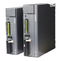
DS5L1-20P2-PTA
User Manuals: Xinje DS5L1-20P2-PTA Servo Drives
Manuals and User Guides for Xinje DS5L1-20P2-PTA Servo Drives. We have
2
Xinje DS5L1-20P2-PTA Servo Drives manuals available for free PDF download: User Manual
Xinje DS5L1-20P2-PTA User Manual (234 pages)
Brand:
Xinje
| Category:
Servo Drives
| Size: 15 MB
Table of Contents
Declaration of Liability
3
Contact Information
3
Safety Precautions
4
Installation Notes
4
Cautions for Wiring
4
Operation Cautions
5
Maintenance and Inspection
5
Table of Contents
7
Confirmation on Product Arrival
10
Selection of Servo System
11
Selection of Servo Driver
11
Model Name
11
Description of each Part
11
Performance Specification
11
Servo Motor Selection
12
Model Name
12
Description of each Part
13
Axial Force and Radial Force
14
Cable Selection
15
Model Name
15
Description of each Part
16
Selection of Other Accessories
19
Selection of Regenerative Resistance
19
Installation of Servo System
20
Servo Driver Installation
20
Installation Site
20
Environment Condition
20
Installation Standard
20
Servo Motor Installation
21
Environment Condition
21
Installation Cautions
22
Installation Environment
23
Servo Cable Installation
24
Cable Selection
24
Xinje Cable Specification
25
Servo Driver Dimension
27
Servo Motor Dimension
29
Servo System Wiring
39
Main Circuit Wiring
40
Servo Driver Terminal Arrangement
40
Main Circuit Terminal
41
CN0, CN2 Terminal
42
Communication Port
43
Classification and Function of Signal Terminals
43
DIP Switch
43
Pulse Signal
44
Input Signal
45
SO Output Signal
46
Operate Panel
47
New Servo Debugging Process
47
Wiring Inspection before Power on and Confirmation of Surrounding Environment
47
Power on
47
Empty Shaft Trial Operation and Debugging
48
Confirmation of Motor Rotation Direction
49
Basic Operation
49
Operating Panel Description
49
Button Operation
50
Status Display Content
51
Status Display in each Operation Mode
51
Zero Clamp(/Zclamp
52
Group U Monitor Parameter
53
Group F Auxiliary Function Parameters
56
Group F1
57
Operation of Servo System
59
Control Mode Selection and Switching
59
Control Mode Selection
59
Control Mode Switching
60
Basic Function Setting
61
Jog Operation
61
Servo Enable Setting
62
Rotation Direction Switching
63
Stop Mode
63
Power-Off Brake
67
Braking Setting
72
Position Control
73
General Position Control
73
Position Control (External Pulse Command)
100
Position Control (Internal Command)
101
Speed Control
111
Speed Mode General Control
111
Speed Control (Internal Speed)
114
Speed Control (Pulse Frequency Command)
117
Torque Control
119
Torque Control (Internal Setting)
119
Absolute Value System
121
Absolute System Setting
121
Replace the Battery
121
The Upper Limit of Turns
123
Read Absolute Position by Communication
123
Clear Multi-Turn
124
Zero Calibration of Absolute Encoder
124
Absolute Value Homing Application
125
Absolute Value Function
126
Auxiliary Functions
127
Anti-Blocking Protection
127
Torque Limit
128
Speed Limit
129
I/O Signal Distribution
129
Output Terminal Function
130
Input Terminal Function
135
Time Limit Curve of Overload Protection
136
Servo Gain Adjustment
138
Overview of Servo Gain Adjustment
138
Overview and Process
138
The Difference of These Adjustment Modes
139
Rotary Inertia Presumption
139
Overview
139
Notes
139
Operation Tool
140
Operation Steps
140
Fast Adjustment
144
Overview
144
Fast Adjustment Steps
144
Rigidity Level Corresponding Gain Parameters
144
Notes
146
Auto-Tuning
147
Overview
147
Notes
147
Operation Tools
147
Internal Instruction Auto-Tuning Steps
148
External Instruction Auto-Tuning Steps
152
Related Parameters
156
Manual Adjustment
157
Overview
157
Adjustment Steps
158
Gain Parameters for Adjustment
159
Adaptive
160
Overview
160
Notes
160
Operation Steps
160
Inertia Mode and Related Parameters
161
Recommended Inertia Ratio Parameters
161
Adaptive Parameters Effect
162
Invalid Parameters When Adaptive Effective
162
Vibration Suppression
163
Overview
163
Operation Tools
163
Vibration Suppression (Panel)
163
Driver Firmware Required 3700 and up
163
Vibration Suppression (PC Software)
164
Vibration Suppression (Manual Setting)
165
Vibration Suppression (Easyfft)
165
Notch Filter
167
Gain Adjustment
168
Model Loop Control
168
Torque Disturbance Observation
170
Gain Adjustment Parameters
171
Gain Switch
171
Gain Adjustment
175
Load Shaking
175
Vibration
175
Noise
175
Alarm
176
Alarm Code List
176
Analysis of Alarm Types
178
Modbus-Rtu Communication
190
Communication Wiring
190
Communication Parameters
191
Communication Protocol
194
Character Structure
194
Communication Data Structure
194
Communication Example
196
Communication with Xinje PLC
196
Appendix
197
Appendix 1. Group Pparameters
197
Monitoring Parameters
215
Appendix 3. Fx-XX Auxiliary Function Parameters
218
Appendix 5. Q&A
223
Appendix 6. General Debugging Steps
225
Appendix 7. Application Example
227
Appendix 8. Servo General Mode Parameters
229
Appendix 8.1 Basic Parameters
229
Appendix 8.2 External Pulse Position Mode General Parameters
229
Appendix 8.3 Internal Position Mode General Parameters
230
Appendix 8.4 Internal Torque Control General Parameters
230
Appendix 8.5 Internal Speed Control General Parameters
230
Appendix 8.6 External Pulse Speed Control General Parameters
231
Appendix 9. Torque-Speed Characteristic Curve
232
Advertisement
Xinje DS5L1-20P2-PTA User Manual (171 pages)
Brand:
Xinje
| Category:
Servo Drives
| Size: 4 MB
Table of Contents
Table of Contents
7
Confirmation on Product Arrival
10
Selection of Servo System
11
Selection of Servo Driver
11
Model Name
11
Description of each Part
11
Performance Specification
12
Servo Motor Selection
12
Model Name
12
Description of each Part
13
Cable Selection
14
Model Name
14
Description of each Part
15
Selection of Other Accessories
16
Selection of Regenerative Resistance
16
Installation of Servo System
18
Servo Driver Installation
18
Installation Site
18
Environment Condition
18
Installation Standard
18
Servo Motor Installation
19
Environment Condition
19
Installation Cautions
20
Installation Environment
21
Servo Cable Installation
22
Cable Selection
22
Xinje Cable Specification
23
Servo Driver Dimension
25
Servo Motor Dimension
26
Servo System Wiring
28
Main Circuit Wiring
29
Servo Driver Terminal Arrangement
29
Main Circuit Terminal
29
CN0, CN2 Terminal
30
Communication Port
31
Classification and Function of Signal Terminals
31
Pulse Signal
31
Input Signal
32
SO Output Signal
32
Operate Panel
34
Basic Operation
34
Operating Panel Description
34
Button Operation
34
Operation Display
35
Group Umonitor Parameter
36
Group Fauxiliary Function Parameters
39
Group F0
39
Group F1
40
Fault Alarm Handling
41
Parameter Setting Example
42
Change Motor Code
42
Operation of Servo System
43
Control Mode Selection and Switching
43
Control Mode Selection
43
Control Mode Switching
44
Basic Function Setting
45
Jog Operation
45
Servo Enable Setting
46
Rotation Direction Switching
47
Stop Mode
47
Power-Off Brake
49
Braking Setting
52
Position Control
53
General Position Control
53
Position Control (External Pulse Command)
62
Position Control (Internal Command)
64
Speed Control
73
Speed Mode General Control
73
Speed Control (Internal Speed)
75
Torque Control
79
Torque General Mode
79
Torque Control (Internal Setting)
79
Absolute Value System
80
Absolute System Setting
80
Replace the Battery
80
The Upper Limit of Turns
81
Auxiliary Functions
82
Anti-Blocking Protection
82
Torque Limit
83
Speed Limit
84
I/O Signal Distribution
84
Output Terminal Function
85
Input Terminal Function
90
Time Limit Curve of Overload Protection
91
Servo Gain Adjustment
93
Overview of Servo Gain Adjustment
93
Overview and Process
93
The Difference of These Adjustment Modes
94
Model Loop Control
94
Torque Disturbance Observation
96
Rotary Inertia Presumption
96
Overview
96
Notes
97
Operation Tool
97
Operation Steps
97
Fast Adjustment
101
Overview
101
Fast Adjustment Steps
101
Rigidity Level Corresponding Gain Parameters
101
Notes
103
Auto-Tuning
104
Overview
104
Notes
104
Operation Tools
104
Internal Instruction Auto-Tuning Steps
104
External Instruction Auto-Tuning Steps
109
Related Parameters
113
Manual Adjustment
114
Overview
114
Adjustment Steps
115
Gain Parameters for Adjustment
116
Adaptive
117
Overview
117
Notes
117
Operation Steps
117
Inertia Mode and Related Parameters
118
Recommended Inertia Ratio Parameters
118
Adaptive Parameters Effect
119
Invalid Parameters When Adaptive Effective
119
Vibration Suppression
120
Overview
120
Operation Tools
120
Vibration Suppression (Panel)
120
Vibration Suppression (PC Software)
121
Vibration Suppression (Manual Setting)
122
Vibration Suppression (Quick FFT)
122
Notch Filter
124
Gain Adjustment
126
Load Shaking
126
Vibration
126
Noise
126
Alarm
127
Alarm Code List
127
Analysis of Alarm Types
129
Appendix
139
Appendix 1. Group Pparameters
139
Appendix 2. Ux-XX Monitoring Parameters
153
Appendix 3. Fx-XX Auxiliary Function Parameters
156
Appendix 5. Q&A
161
Appendix 6. General Debugging Steps
163
Appendix 7. Application Example
164
Appendix 8. Servo General Mode Parameters
166
Appendix 8.1 Basic Parameters
166
Appendix 8.2 External Pulse Position Mode General Parameters
166
Appendix 8.3 Internal Position Mode General Parameters
167
Appendix 8.4 Internal Torque Control General Parameters
167
Appendix 8.5 Internal Speed Control General Parameters
167
Appendix 8.6 External Pulse Speed Control General Parameters
168
Appendix 9. Torque-Speed Characteristic Curve
169
Advertisement
Related Products
Xinje DS5L1-2 P Series
Xinje DS5L1-20P1-PTA
Xinje DS5L1-20P4-PTA
Xinje DS5L1-20P7-PTA
Xinje DS5L1-21P0-PTA
Xinje DS5L1-21P5-PTA
Xinje DS5L1-22P3-PTA
Xinje DS5L1-22P6-PTA
Xinje DS5L1-41P0-PTA
Xinje DS5L1-42P3-PTA
Xinje Categories
Servo Drives
Control Unit
Controller
Computer Hardware
Media Converter
More Xinje Manuals
Login
Sign In
OR
Sign in with Facebook
Sign in with Google
Upload manual
Upload from disk
Upload from URL