Sign In
Upload
Manuals
Brands
XIMEA Manuals
Digital Camera
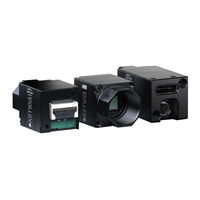
xiMU MU9PC-MH
XIMEA xiMU MU9PC-MH Manuals
Manuals and User Guides for XIMEA xiMU MU9PC-MH. We have
2
XIMEA xiMU MU9PC-MH manuals available for free PDF download: Technical Manual
XIMEA xiMU MU9PC-MH Technical Manual (109 pages)
Brand:
XIMEA
| Category:
Digital Camera
| Size: 3 MB
Table of Contents
About this Manual
2
About XIMEA
2
Contact XIMEA
2
Standard Conformity
3
Standard Conformity CE Logo
3
Standard Conformity UKCA Logo
3
Fcc Conformity
3
Standard Conformity FCC Logo
3
Rohs Conformity
4
Standard Conformity Rohs Logo
4
WEEE Conformity
4
Standard Conformity WEEE Logo
4
Helpful Links
5
Table of Contents
6
Ximu Camera Series
9
What Is Ximu
9
Advantages
9
Camera Applications
10
Common Features
10
Model Nomenclature
11
Models and Sensors Overview
12
List of Camera Models and Their Respective Sensor Models and Filters
12
Accessories Overview
13
Bob-Mq-Fl
13
Ximu Accessories
13
Hardware Specification
14
Power Supply
14
Power Input
14
General Specification
15
Environment
15
Lens Mount
16
S-Mount
16
Lens Mount Adapter S-Mount (M12-M) (Left), Camera with Adapter (Right)
16
Lens Mount Adapter S-Mount (M12-L) (Left) , Camera with Adapter (Right)
16
Mounting Points
17
Screws
17
Ximu Camera Mounting Points
17
M2 Mounting Screws
17
M2 Screw Description
17
Optical Path
18
Cross Section of Mu050Xr-SY Camera Models
18
Cross Section of Mu051Xg-SY Camera Models
18
Cross Section of Mu196Xr-ON Camera Models
19
Sensor and Camera Characteristics
21
Sensor and Camera Parameters
21
Image Quality Parameters
22
Image Quality Parameters Of: MU051CG-SY
22
Image Quality Parameters Of: MU051MG-SY
23
Sensor Read-Out Modes
24
Sensor Read-Out Modes Of: MU051CG-SY
24
Sensor Read-Out Modes Of: MU051MG-SY
24
Sensor Read-Out Modes Of: MU196CR-ON
25
Sensor Read-Out Modes Of: MU196MR-ON
26
Quantum Efficiency Curves
27
Graph Quantum Efficiency of Sony IMX675
27
Graph Quantum Efficiency of Sony IMX568
27
Graph Quantum Efficiency of Onsemi AR2020
28
Mechanical Characteristics
29
Dimensions and Mass
29
Dimensional Drawings
30
Dimensional Drawings of Mu051Xg-SY
30
Dimensional Drawings of Mu196Xr-ON and Mu050Xr-SY
31
Camera Interface
32
Data Connector Location
32
Data Connector Pinning
32
Data Mating Connector Description
32
Digital Inputs / Outputs (GPIO) Interface
33
I/O Connector Pin Assignment
34
Non-Isolated Digital Lines (Connected to Sensor as Well) - Digital Input-Output 1.8V Logic (INOUT)
37
Non-Isolated Input/Output, Interface Schematic with Sensor
37
General Info for Non-Isolated Digital In/Out Trigger Lines Which Are Connected Directly to Sensor
37
Non-Isolated Digital Lines - Digital Input-Output 1.8V Logic (INOUT)
38
Non-Isolated Input/Output, Interface Schematic
38
General Info for Non-Isolated Digital In/Out Trigger Lines
38
Accessories
39
Me-Adpt-Mu-T-Kit
39
Isometric of Camera with ME-ADPT-MU-T
39
Dimensional Drawing of ME-ADPT-MU-T
39
Mechanical Parameters of ME-ADPT-MU-T
39
ME-ADPT-MU-17X17-T
40
Isometric View of ME-ADPT-MU-17X17-T
40
Dimensional Drawing of ME-ADPT-MU-17X17-T
40
Mechanical Parameters of ME-ADPT-MU-17X17-T
40
ADPT-MU-CX3-FL / ADPT-MU-17X17-CX3-FL
41
Flex Connectors Location ADPT-MU-CX3-FL / ADPT-MU-CX3-FV
41
ADPT-MU-CX3-FL / ADPT-MU-CX3-FV Connectors Pinout
41
ADPT-MU-CX3-FL / ADPT-MU-CX3-FV Connectors Description
41
ADPT-MU-CX3-FL / ADPT-MU-CX3-FV Connectors Pin Assignment
41
General Info for Digital Input, ADPT-MU-CX3-FL / ADPT-MU-CX3-FV Adapters
42
General Info for Digital Ouput, ADPT-MU-CX3-FL / ADPT-MU-CX3-FV Adapters
42
Dimensional Drawings
43
Dimensional Drawing of Mu050Xr-SY with ADPT-MU-CX3-FL Adapter
43
Dimensional Drawing of Mu051Xr-SY with ADPT-MU-17X17-CX3-FL Adapter
44
Dimensional Drawing of Mu196Xr-ON with ADPT-MU-CX3-FL Adapter
45
Connecting the Components
46
Connecting Steps, Camera with ADPT-MU-CX3-TC-FV / ADPT-MU-CX3-TC-FL Adapter
46
ADPT-MU-CX3-TC-V / ADPT-MU-17X17-CX3-TC-V
47
Isometric View of ADPT-MU-TC-V
47
ADPT-MU-CX3-TC-V Connectors Location
47
ADPT-MU-CX3-TC-V Connectors
47
ADPT-MU-CX3-TC-V USB3 Type-C Connector Pinout
48
ADPT-MU-CX3-TC-V USB3 Type-C Connector Description
48
ADPT-MU-CX3-TC-V USB3 Type-C Connector Pin Assignment
48
ADPT-MU-CX3-TC-V IO Connector Pinout
49
ADPT-MU-CX3-TC-V GPIO Connector Description
49
GPIO Connector Pin Assignment
49
General Info for Digital Input / Output, ADPT-MU-CX3-TC-V Adapter
50
General Info for Digital Output, ADPT-MU-CX3-TC-V Adapter
50
Dimensional Drawing of Mu050Xr-SY with ADPT-MU-CX3-TC-V Adapter
51
Dimensional Drawing of Mu051Xr-SY with ADPT-MU-17X17-CX3-TC-V Adapter
52
Dimensional Drawing of Mu196Xr-ON with ADPT-MU-CX3-TC-V Adapter
53
ADPT-MU-CX3-UC / ADPT-MU-17X17-CX3-UC
54
Location of Connector
54
ADPT-MU-CX3-UC Connector Pinout
54
ADPT-MU-CX3-UC Connector Description
54
ADPT-MU-CX3-UC Connector Pin Assignment
54
General Info for Digital Input / Output, ADPT-MU-CX3-UC Adapter
55
General Info for Digital Output, ADPT-MU-CX3-UC Adapter
55
Dimensional Drawing of Mu050Xr-SY with ADPT-MU-CX3-UC Adapter
56
Dimensional Drawing of Mu051Xr-SY with ADPT-MU-17X17-CX3-UC Adapter
57
Dimensional Drawing of Mu196Xr-ON with ADPT-MU-CX3-UC Adapter
58
Bob-Mq-Fl
59
BOB-MQ-FL Dimensions
59
IO Connector (WAGO 218-104), Pin Assignment
59
General Features
60
Camera Features
60
Rois - Region of Interest
60
Downsampling Modes
60
Image Data Output Formats
61
Acquisition Modes
64
Free-Run
64
Trigger Controlled Acquisition/Exposure
64
Software Trigger
64
Hardware Trigger
64
Acquisition Mode - Free Run
64
Triggered Burst of Frames - Frame Burst Start
65
Triggered Burst of Frames - Frame Burst Active
65
Set Exposure
66
Exposure Time
67
Gain
67
Dual ADC Modes
68
Dual ADC Non-Combined Without Merging
68
Non-Combined Mode
69
Dual ADC Non-Combined with Merging
69
Combined Mode
70
Dual ADC Combined Mode
70
Sensor Shutter Modes
71
Global Reset Release Mode
71
Global Reset Release Mode - Schematic
71
Global Reset Release Mode - Image Horizontally Moved Object
71
Global Reset Release Mode with Flash - Schematic
71
Rolling Shutter Mode
72
Rolling Shutter Mode - Schematic
72
Rolling Shutter Mode Image of a Horizontally Moved Object
72
Rolling Shutter Mode with Flash - Schematic
72
How to Freeze the Motion
73
API Features
74
Exposure - Auto Gain
74
White Balance
74
Gamma
74
Sharpness
74
Color Correction Matrix
74
Sensor Defect Correction
74
Operation
75
System Requirements
75
Software Requirements
75
Hardware Requirements
75
XIMEA Software Packages
76
XIMEA Windows Software Package
76
Installation
76
XIMEA Linux Software Package
79
XIMEA Macos Software Package
81
Start XIMEA Camtool
83
Short Description
83
XIMEA Camtool
84
XIMEA Control Panel
85
Xicop Example
85
Supported Vision Libraries
86
Mathworks MATLAB
86
Mvtec HALCON
86
National Instruments Labview Vision Library
86
Opencv
86
Programming
87
Standard Interface
87
Xiapi
87
Open Interface
87
Get Parameter
87
Set Parameter
87
GPIO Schematic
89
Select Trigger Source
89
Appendix
91
Troubleshooting and Support
91
Worldwide Support
91
Before Contacting Technical Support
91
Frequently Asked Questions
91
Product Service Request (PSR)
92
Step 1 - Contact Support
92
Step 2 - Create Product Service Request (PSR)
92
Step 3 - Wait for Product Service Request (PSR) Approval
92
Step 4 - Sending the Camera to XIMEA
92
Step 5 - Waiting for Service Conclusion
92
Service Operations Overview
92
Step 6 - Waiting for Return Delivery
93
Safety Instructions and Precautions
94
Disassembly
94
Mounting / Screws
94
Connections
94
Power Supply
94
Environment / Protection against Water
94
Recommended Light Conditions
94
Protection of Optical Components
95
Mechanical Loads
95
Camera / Lens Cleaning
95
Protect against Static Discharge (Electrostatic Discharge (ESD))
95
Safety Instruction for Board Level Cameras
95
Warranty
96
Disclaimer of Warranty
96
Standard Terms & Conditions of XIMEA Gmbh
97
List of Trademarks
103
Advertisement
XIMEA xiMU MU9PC-MH Technical Manual (97 pages)
Brand:
XIMEA
| Category:
Digital Camera
| Size: 4 MB
Table of Contents
1 Introduction
2
About this Manual
2
About XIMEA
2
Contact XIMEA
2
Standard Conformity
3
CE Conformity
3
For Customers in the US: FCC Conformity
3
For Customers in Canada
3
Rohs Conformity
3
WEEE Conformity
4
Genicam Gentl API
4
Helpful Links
4
Table of Contents
5
2 Ximu USB2.0 and USB3.1 Gen 1 Camera Series
10
What Is Ximu
10
Advantages
11
Camera Applications
11
Common Features
11
Models Overview
12
USB2.0 Models
12
USB3.1 Gen 1 Models
12
Accessories
13
3 Ximu Hardware Specification
14
General Specification
14
Environment
14
Heat Dissipation
14
Firmware / Host Driver / API Features
14
Power Supply
14
Optical Path
15
Ximu USB2.0 Specification
15
Sensor and Camera Parameters
15
Quantum Efficiency Curves [%]
16
Dimensional Drawings (Without Lens Mount Adapter)
17
Referenced Documents
17
Camera Features
17
MU9 Lens Mount Adapters
18
MECH-MU9-MH-ADAPT-M, Dimensional Drawing
18
MECH-MU9-MH-ADAPT-L, Dimensional Drawing
19
MU9 Camera Connector (USB / IO Interface)
20
Location and Pinout
20
Signal Description
21
Gxn DC Electrical Characteristics
22
MU9 Patch Cable
23
Signal Description (USB 2.0 Connector)
23
Signal Description (IO Connector)
23
Connection of Patch Cable
23
Mu-Miniusb
24
Adpt-Mu9P-Usb2-Ub-V
26
Me-Adpt-Mu-T
28
Dimensional Drawing
28
Cbl-Mqsync-3M0
29
Scope of Delivery (Mu9Px-MH)
30
Scope of Delivery (Mu9Px-MH-KIT)
30
Scope of Delivery (MU9PX-MBRD)
30
Scope of Delivery MU-MINIUSB
30
Scope of Delivery ADPT-MU9P-USB2-UB-V
31
Ximu USB3.1 Gen1 Specification
32
Sensor and Camera Parameters
32
Quantum Efficiency Curves [%]
33
Dimensional Drawings
34
Camera Features
35
MU181 Lens Mount Adapters
36
ME-LA-MU-M12-M, Dimensional Drawing
36
ME-LA-MU-M12-L, Dimensional Drawing
37
MU181CR-ON Camera Connector (USB / IO Interface)
38
Location and Pinout
38
Signal Description
39
Gxn Electrical Characteristics
40
Adpt-Mu-Fl, Adpt-Mu-Fv
41
Flex Connection Location
41
Pinning
42
IO Lines Specification
43
IO Connection to Camera
44
Inserting / Detaching FPC Cable
45
Adpt-Mu-Tc-V
48
IO Connector Pinout
48
Me-Adpt-Mu-T
49
Cbl-Mqsync-3M0
49
Cbl-Mq-Fl-0M1, Cbl-Mq-Fl-0M25
49
Cbl-Usb3Flex-0M10, Cbl-Usb3Flex-0M25, Cbl-Usb3Flex-0M50
49
Bob-Mq-Fl
50
Scope of Delivery MU181CR-ON Models
51
Scope of Delivery ADPT-MU-FL/ADPT-MU-FV
51
Scope of Delivery ADPT-MU-TC-V
51
Scope of Delivery ME-ADPT-MU-T Kit
52
4 Operation
53
System Requirements
53
Software Requirements
53
Hardware Requirements
53
Video Formats
53
Full Resolution
53
Rois - Region of Interest
53
Downsampling Modes
53
Binning
54
Skipping/Decimation
54
Color and Mono Modes
54
Acquisition Modes
55
Free-Run
55
Triggered Acquisition
55
Software Trigger
55
Hardware Trigger
55
Triggered Mode
56
Sensor Shutter Modes
58
Rolling Shutter Mode
58
Global Reset Release Mode
59
How to Freeze the Motion
60
Camera Parameters and Features
60
Exposure
60
Gain
60
Host-Assisted Image Processing Parameters Available in Xiapi
60
Auto Exposure - Auto Gain
60
White Balance
60
Assisted Manual White Balance
60
Auto White Balance
61
Gamma
61
Sharpness
61
Color Correction Matrix
61
Bad Pixel Correction
61
MU9 USB2.0 Transfer Modes
61
Transfer Mode
61
Packet Size Setting
61
Bandwidth Control
62
USB Hubs
62
Using Multiple MU9 Cameras
62
Connecting Two MU9 Cameras with Synchronized Acquisition
62
Interconnect Cameras
62
Connect Cameras to PC
63
Control the Cameras with Xiapi
63
5 Software
65
Accessing the Camera
65
Proprietary API
65
Standard Interface
65
Genicam
65
Vision Library Integration
65
XIMEA Camtool
66
Supported Vision Libraries
68
Libraries Maintained by XIMEA
68
Mathworks MATLAB
68
Mvtec HALCON
68
National Instruments Labview Vision Library
68
Opencv
68
XIMEA Windows Software Package
69
Contents
69
Installation
69
XIMEA Linux Software Package
72
Contents
72
Installation
72
XIMEA Macos Software Package
74
Contents
74
Installation
74
Start XIMEA Camtool
75
Programming
76
XIMEA Apis
76
Xiapi Overview
76
Xiapi Functions Description
76
Xiapi Parameters Description
77
Xiapi Examples
77
Connect Device
77
Parameterize Device
77
Acquire Images
78
Control Digital Input / Output (GPIO)
78
Xiapi Auto Bandwidth Calculation
79
Genicam
79
XIMEA Control Panel
80
6 Appendix
81
Troubleshooting and Support
81
Worldwide Support
81
Before Contacting Technical Support
81
Frequently Asked Questions
81
Product Service Request (PSR)
82
Step 1 - Contact Support
82
Step 2 - Create Product Service Request (PSR)
82
Step 3 - Wait for PSR Approval
82
Step 4 - Sending the Camera to XIMEA
82
Step 5 - Waiting for Service Conclusion
82
Step 6 - Waiting for Return Delivery
82
Safety Instructions and Precautions
83
Disassembling
83
Mounting / Screwing
83
Connections
83
Power Supply
83
Environment / Protect against Water
83
Recommended Light Conditions
83
Protect the Optical Components
84
Mechanical Loads
84
Camera / Lens Cleaning
84
Protect against Static Discharge (ESD)
84
Safety Instructions for Board Level Cameras
84
Warranty
85
Disclaimer of Warranty
85
List of Trademarks
85
Standard Terms & Conditions of XIMEA Gmbh
86
Copyright
91
Revision History
92
7 Glossary
93
8 List of Figures
94
9 List of Tables
96
Advertisement
Related Products
XIMEA xiMU MU9PM-MH
XIMEA xiMU MU9PM-MBRD
XIMEA xiMU MU9PC-MBRD
XIMEA xiMU MU181CR-ON
XIMEA xiMU MU050MR-SY
XIMEA xiMU MU051MG-SY
XIMEA xiMU MU051CG-SY
XIMEA xiMU MU196MR-ON
XIMEA MU050CR-SY
XIMEA MU196CR-0N
XIMEA Categories
Digital Camera
Adapter
Media Converter
Machine Vision Systems
Switch
More XIMEA Manuals
Login
Sign In
OR
Sign in with Facebook
Sign in with Google
Upload manual
Upload from disk
Upload from URL