Sign In
Upload
Manuals
Brands
Xenics Manuals
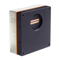
Digital Camera
XEN-000657
Xenics XEN-000657 Manuals
Manuals and User Guides for Xenics XEN-000657. We have
1
Xenics XEN-000657 manual available for free PDF download: User Manual
Xenics XEN-000657 User Manual (73 pages)
Manx-camera
Brand:
Xenics
| Category:
Digital Camera
| Size: 3 MB
Table of Contents
Revision History
3
Change Details
3
Table of Contents
4
List of Figures
6
List of Tables
8
1 Introduction
9
Scope
9
Reference Documents
9
Table 1-1 Camera Overview - Manx
9
Table 1-2 List of Reference Documents
9
Manual Overview
10
Conventions Used in this Manual
10
Safety Warnings
10
Contact Information
11
2 Getting Started
12
Installation of Coaxpress Frame Grabber
12
Installation of Xeneth User Interface Software
12
Installation of Xeneth SDK
12
Connect the Camera Via Xeneth
13
Figure 2-1 Connect Camera to Xeneth
13
Acquiring the First Images
14
Figure 2-2 Xeneth User Interface Layout
14
3 Mechanical Overview
15
Figure 3-1 2D CAD of Manx - Tolerance ISO 2768 - F H
15
Optical Position
16
4 Electrical Interface
16
Unified Lemo Connector
16
Figure 3-2 Optical Position of Ingaas Detector
16
Coaxpress Interface
17
5 Camera Functionality
17
Table 4-1 Connector Pinout
17
Image Acquisition
18
Figure 5-1 Show Camera Property Documentation
18
Figure 5-2 Gain Selection on Xeneth
18
Table 5-1 Analogue Gain Settings
18
Figure 5-3 Exposure Time Setting on Xeneth
19
Figure 5-4 Acquisition Line Time Setting in Xeneth
19
Figure 5-5 Acquisition Frame Time Setting on Xeneth
20
Figure 5-6 Acquisition Control Settings on Xeneth
21
Figure 5-7 Frame Height Setting on Xeneth
21
Table 5-2 Acquisition Control
21
Figure 5-8 Footer Settings on Xeneth
22
Figure 5-9 Footer Enabled
22
Tec Control
23
Figure 5-10 Tec Regulation Settings on Xeneth
23
Table 5-3 Footer Contents of the Manx
23
Triggering
24
Figure 5-11 Example of a Frame Capturing for the Manx Camera
24
Table 5-4 Factors Affecting Line(Frame) Period
24
Figure 5-12 Free Running Internal Trigger
25
Figure 5-13 Trigger Period Longer than Line(Frame) Period
25
Figure 5-14 Trigger Period Is Shorter than Line(Frame) Period
26
Table 5-5 Trigger Sources
26
Table 5-6 Trigger in Voltages
26
Table 5-7 Trigger in Source Configurations
27
Table 5-8 Line(Frame) Trigger in Polarity Configuration
27
Figure 5-15 Trigger in Settings as Shown on Xeneth
28
Figure 5-16 Trigger in Delay
28
Table 5-9 Multiple Lines(Frames) Per Trigger
28
Figure 5-17 Multiple Lines(Frames) Per Trigger Setting on Xeneth
29
Table 5-10 Digital Output (Trigger Output) Mode
30
Table 5-11 Trigger out Voltages and Impedance
30
Table 5-12 Tigger out Source
30
Figure 5-18 Trigger out Pulse at Start of Frame and Line
31
Figure 5-19 Digital Output (Trigger Output) Settings on Xeneth
31
Image Processing
32
Figure 5-20 Digital Gain and Offset Settings on Xeneth
32
Table 5-13 Digital Fixed Gain and Offset
32
Figure 5-21 Select Software Calibration File
33
Table 5-14 Factory Default Calibration Files
33
Figure 5-22 Typical Corrected Image with Uniform Lightings
34
Figure 5-23 Typical Raw Image with Uniform Lighting
35
Figure 5-24 Enable Software Calibration File
35
Figure 5-25 Enable Onboard Calibration
36
Table 5-15 Factory Default Onboard Calibration File Slots
36
Camera Non-Volatile Memory
37
Figure 5-26 Free Onboard Calibration Slot
37
Figure 5-27 Unavailable Onboard Calibration Slot
37
Figure 5-28 Upload Calibration File
37
Figure 5-29 Saving User Set Settings
38
Figure 5-30 Clearing Existing User Set Settings
39
Figure 5-31 Allocating Power up Default Setting
39
Figure 5-32 Starting up a Camera with User Set Default Settings
40
Figure 5-33 User Set Default Setting in Used
40
6 Appendix
41
Appendix A - Euresys Coaxlink Quad G3 Installation Manual
41
Figure 6-1 Coaxpress Download Files from Euresys
41
Figure 6-2 Windows Start Menu with Euresys Genicam Browser Installed
41
Figure 6-3 GEN3 Pice X4 Slot on the Motherboard
42
Figure 6-4 Power Supply for the Frame Grabber Board
42
Figure 6-5 Coaxpress Frame Grabber Board Not Ready
42
Figure 6-6 Coaxexpress Frame Grabber Board Detected on Device Manager
43
Figure 6-7 Update Coaxpress Frame Grabber Board Firmware
43
Figure 6-8 Coaxpress Sequence on Manx
44
Figure 6-9 Coaxpress Sequence on Frame Grabber
44
Figure 6-10 Coaxpress Connection Ready
44
Appendix B - Graphical Representation of Trigger in Configurations
45
Figure 6-11Pcienegotiatedlinkwidth
45
Figure 6-12 Continuous Acquisition, Line- and Frame Trigger Free Running
46
Table 6-1 Continuous Acquisition, Line- and Frame Trigger Free Running
46
Figure 6-13 Continuous Acquisition with Frame Trigger External and Line Trigger Free Running
47
Table 6-2 Continuous Acquisition with Frame Trigger External and Line Trigger Free Running
47
Figure 6-14 Continuous Acquisition with Frame Trigger Free Running and Line Trigger External
48
Table 6-3 Continuous Acquisition with Frame Trigger Free Running and Line Trigger External
48
Figure 6-15 Continuous Acquisition with Line and Frame Trigger External
49
Table 6-4 Continuous Acquisition with Line and Frame Trigger External
49
Figure 6-16 Continuous Acquisition with Multi Frame Trigger
50
Table 6-5 Continuous Acquisition with Multi Frame Trigger
50
Figure 6-17 Multiframe Acquisition
51
Table 6-6 Multiframe Acquisition
51
Figure 6-18 Multiframe Acquisition with Frame Trigger
52
Table 6-7 Multiframe Acquisition with Frame Trigger
52
Figure 6-19 Multiframe Acquisition with Multi Frame Trigger
53
Table 6-8 Multiframe Acquisition with Multi Frame Trigger
53
Appendix C - Non Uniformity Correction (NUC)
54
Figure 6-20 Load Calibration Wizard
54
Figure 6-21 Two Point Calibration
55
Figure 6-22 Two Point Calibration Dark Offset Analysis
56
Figure 6-23 Selected Bad Pixels from Dark Offset Analysis
56
Figure 6-24 2/3 of Histogram
57
Figure 6-25 View Histogram
57
Figure 6-26 Two Point Calibration Flat Field Image Analysis
58
Figure 6-27 Selected Bad Pixel from Flat Field Image Analysis
58
Figure 6-28 Edit Bad Pixel Map
59
Figure 6-29 Disable Software Image Correction
60
Figure 6-30 Disabled Software Image Correction
60
Figure 6-31 Load Calibration Wizard
60
Figure 6-32 Recalibration Offset
61
Figure 6-33 One Point Dark Offset Analysis
62
Figure 6-34 Selected Bad Pixel from Dark Offset Analysis
62
Appendix D - Firmware and XML Upgrade
63
Figure 6-35 Setting Tab - Storage Icon
63
Figure 6-36 Firmware Upgrade File Selection
64
Figure 6-37 Firmware Uploading in Process
64
Figure 6-38 XML Upgrade File Seletion
65
Figure 6-39 XML Uploading in Process
65
Appendix E - Register Description
66
Table 6-9 Acquisition and Trigger Control Registers
68
Table 6-10 Image Correction and Processing Control Registers
69
Table 6-11 Image Format Control Registers
69
Table 6-12 Digital Output Control Registers
70
Table 6-13 Device Control Registers
71
Table 6-14 File Access Control Registers
72
Table 6-15 User Set Control Registers
73
Table 6-16 User Set Enumeration
73
Advertisement
Advertisement
Related Products
Xenics XEN-000651
Xenics XEN-000652
Xenics XEN-000653
Xenics XEN-000654
Xenics XEN-000655
Xenics XEN-000656
Xenics XEN-000658
Xenics XEN-000659
Xenics XEN-000686
Xenics XEN-000688
Xenics Categories
Digital Camera
Color Camera
More Xenics Manuals
Login
Sign In
OR
Sign in with Facebook
Sign in with Google
Upload manual
Upload from disk
Upload from URL