Sign In
Upload
Manuals
Brands
XCell Manuals
Motorized Toy Car
Fury Extreme
XCell Fury Extreme Manuals
Manuals and User Guides for XCell Fury Extreme. We have
1
XCell Fury Extreme manual available for free PDF download: Assembly Manual
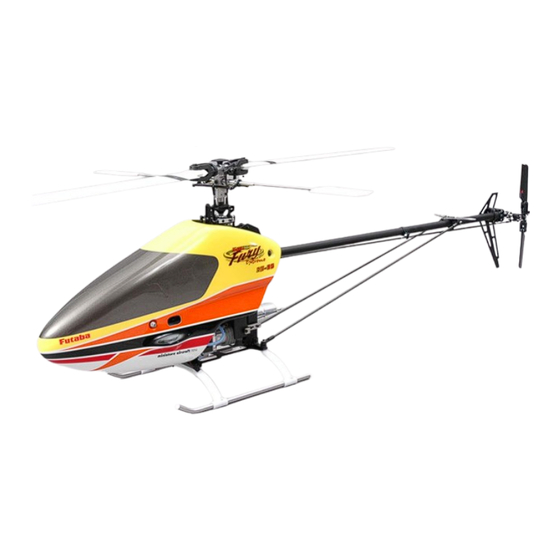
XCell Fury Extreme Assembly Manual (138 pages)
Version 1.0
Brand:
XCell
| Category:
Motorized Toy Car
| Size: 8 MB
Table of Contents
Table of Contents
3
Revisions to this Manual
6
Errata
6
Kit Introduction
7
R/C Helicopter Safety
7
Guidelines for Safe R/C Helicopter Flight
7
X-Cell Limited Warranty
8
Warranty Procedures
8
X-Cell Extreme Warranty Registration
8
Kit Prerequisites
9
Supplies Needed for Assembly
9
Adhesives Used
9
Tools Needed for Assembly
10
Additional Components Needed
11
Kit Assembly Process
13
Assembly Tips
13
Fastener Guide
13
Step #1 - Gear Ratios
15
A) Gear Ratio - Bag #1A - Kit Specific
15
8:18 Ratio
15
8:45 Ratio
16
Step #2 - Left Frame
17
A) Main Frame Components - Bag #2A
17
B) Frame Fasteners - Bag #2B
18
- Assemble Left Frame - Part 1
19
B.1 – Assemble Left Frame – Part 1
19
- Assemble Left Frame - Part 2
21
B.2 – Assemble Left Frame – Part 2
21
C) Drive Train Components - Bag #2C
23
- Install Drive Train Components
24
C.1 – Install Drive Train Components
24
D) Constant Drive - Bag #2D
26
- Assemble Constant Drive Unit
27
- Install Main Shaft/Collars
29
D.2 – Install Main Shaft/Collars
29
- Install Constant Drive
30
D.3 – Install Constant Drive
30
- Install Left Gear Ratio Plate
31
E) Clutch Assembly - Bag #2E
32
- Assemble Clutch
33
- Install Clutch Assembly
34
Step #3 - Right Frame
37
A) Right Frame - Bag #3A
37
B) Right Frame Components - Bag #3B
38
- Assemble Right Frame
39
B.1 – Assemble Right Frame
39
- Install Right Frame
41
B.2 – Install Right Frame
41
- Install Right Ratio Plate
43
- Install Landing Gear Mounts
45
B.4 – Install Landing Gear Mounts
45
C) Control Bellcranks - Bag #3C
46
- Assemble Aileron/Pitch Bellcranks
47
C.1 – Assemble Aileron/Pitch Bellcranks
47
- Install Aileron/Pitch Bellcranks
48
C.2 – Install Aileron/Pitch Bellcranks
48
- Assemble Elevator Bellcrank
49
- Install Elevator Bellcrank
50
- Assemble Rudder Bellcrank
51
- Install Rudder Bellcrank
52
Step #4 - Frame Assembly
53
A) Chassis Components - Bag #4A
53
B) Engine Components - Bag #4B
54
- Prepare Engine
55
B.1 – Prepare Engine
55
- Install Engine Mounts
57
B.2 – Install Engine Mounts
57
- Install Engine
59
B.3 – Install Engine
59
C) Landing Gear - Bag #4C
60
- Assemble/Install Landing Gear/Frame Bottom Plate
60
D) Fan Shroud Mounts - Bag #4D
62
- Assemble/Install Fan Shroud/Mounts
63
- Install Muffler
64
D.3 – Install Muffler
64
Step #5 - Fuel Tank
67
A) Fuel Tank - Bag 5A
67
- Assemble Fuel Tank
68
- Install Fuel Tank
70
Step #6 - Swashplate/Washout Mixer
71
A) Swashplate - Bag #6A - Kit Specific
71
- Assemble Swashplate
72
- Install Swashplate - 140° Kit
74
A.2 - Install Swashplate – 140° Kit
74
B) Washout Mixer - Bag #6B
75
- Assemble Washout Mixer
76
- Install Washout Mixer
78
- Assemble Swashplate Control Rods
79
- Install Swashplate Control Rods
79
B.3 – Assemble Swashplate Control Rods
79
Step #7 - Control System/Canopy
80
A) Servo Mounts - Bag #7A
80
- Install Servos/Radio Gear
81
A.1 – Install Servos/Radio Gear
81
B) Ball Links - Bag #7B
84
C) Control Rods - Bag #7C
85
- Assemble Servo Control Rods
85
D) Servo Supports - Bag #7D
87
- Assemble/Install Servo Wheels
88
D.1 – Assemble/Install Servo Wheels
88
- Install Servo Control Rods
90
D.2 – Install Servo Control Rods
90
- Install Servo Supports
91
D.3 – Install Servo Supports
91
E) Canopy Mounts - Bag #7E
92
- Assemble Canopy Knobs
92
F) Canopy - Box Contents
93
- Prepare Canopy
94
F.1 – Prepare Canopy
94
Step #8 - Rotor Head
95
A) Head Block - Bag #8A
95
- Head Block Assembly
96
B) Blade Grips - Step #8B
97
- Assemble Bell Mixer
98
B.1 – Assemble Bell Mixer
98
- Install Bell Mixers
99
B.2 – Install Bell Mixers
99
C) Head Axle Components - Bag #8C
100
- Blade Arm Assembly
101
- Assemble Blade Arms
101
- Install Blade Arms
103
C.2 – Install Blade Arms
103
D) Flybar - Bag #8D
104
- Assemble/Install Flybar Control System
105
- Assemble/Install Flybar Bell Links
106
- Install Flybar
107
- Install Flybar Paddles
107
D.3 – Install Flybar
107
- Install Rotor Head
108
D.5 – Install Rotor Head
108
Step #9 - Tail Rotor Assembly
109
A) Tail Rotor Hub - Bag #9A
109
- Assemble Tail Rotor Hub
110
A.1 – Assemble Tail Rotor Hub
110
- Install Tail Rotor Blades
112
A.2 – Install Tail Rotor Blades
112
B) Tail Rotor Pitch Yoke - Bag #9B
113
- Assemble TR Pitch Yoke
114
B.1 – Assemble TR Pitch Yoke
114
C) Tail Rotor Transmission - Bag #9C
116
- Assemble T/R Bellcrank
117
C.1 – Assemble T/R Bellcrank
117
- Install T/R Bellcrank
118
C.2 – Install T/R Bellcrank
118
- Install T/R Pitch Yoke
119
C.3 – Install T/R Pitch Yoke
119
Step #10 - Locate Tail Boom Components
120
A) Tail Boom Components - Bag #10
120
Step #11 - Tail Boom Assembly
121
A) Tail Boom Mounts - Bag #11A
121
- Install T/R Transmission
122
A.2 – Install T/R Transmission
122
- Install Vertical Fin Mount/Fin
123
- Install Horizontal Fin Mount/Fin
125
- Install Tail Rotor
127
A.5 – Install Tail Rotor
127
- Install Front Tail Boom Mount
128
B) Tail Rotor Pushrod Components - Bag #11B
129
- Assemble/Install T/R Pushrod Guide
130
- Install Tailboom
130
B.1 – Assemble/Install T/R Pushrod Guide
130
- Assemble T/R Pushrod
131
B.3 – Assemble T/R Pushrod
131
- Install T/R Pushrod
132
B.4 – Install T/R Pushrod
132
C) Tail Boom Support Components - Bag #11C
133
- Assemble Tail Boom Supports
133
- Install Tail Boom Supports
134
C.2 – Install Tail Boom Supports
134
- Install Rotor Blades
135
- Install Canopy
135
C.3 – Install Rotor Blades
135
Advertisement
Advertisement
Related Products
XCell Ion-X2
XCell Razor 600E
XCell Categories
Laboratory Equipment
Battery Charger
Motorized Toy Car
Flood Light
Solar panel
More XCell Manuals
Login
Sign In
OR
Sign in with Facebook
Sign in with Google
Upload manual
Upload from disk
Upload from URL