Sign In
Upload
Manuals
Brands
Woodward Manuals
Recording Equipment
SPM-D10B/PSY5-FU-A
Woodward SPM-D10B/PSY5-FU-A Manuals
Manuals and User Guides for Woodward SPM-D10B/PSY5-FU-A. We have
1
Woodward SPM-D10B/PSY5-FU-A manual available for free PDF download: Manual
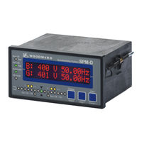
Woodward SPM-D10B/PSY5-FU-A Manual (69 pages)
Synchronizing Unit
Brand:
Woodward
| Category:
Recording Equipment
| Size: 4 MB
Table of Contents
Table of Contents
3
Chapter 1. General Information
6
Chapter 2. Electrostatic Discharge Awareness
7
Chapter 3. Installation
8
Wiring Diagram
9
SPM-D10B/PSY5-FU-D (Power Supply: 24 VDC)
9
Figure 3-1: Wiring Diagram SPM-D10B/PSY5-FU-D
9
SPM-D10B/PSY5-FU-A (Power Supply: 24 VDC)
10
Figure 3-2: Wiring Diagram SPM-D10B/PSY5-FU-A
10
SPM-D10B/PSY5-FU-D-W (Power Supply: 90
11
Figure 3-3: Wiring Diagram SPM-D10B/PSY5-FU-D-W
11
SPM-D10B/PSY5-FU-A-W (Power Supply: 90
12
Figure 3-4: Wiring Diagram SPM-D10B/PSY5-FU-A-W
12
Reference Point
13
Power Supply (Standard & SPM-D10B/PSY5
13
Figure 3-5: Reference Point
13
Figure 3-6: Power Supply (24 VDC, Standard)
13
Figure 3-7: Power Supply (90
13
Measuring Inputs
14
System 2
14
Figure 3-8: Measuring Inputs - Voltage System 2
14
System 1
15
Figure 3-9: Measuring Inputs - Voltage System 1
15
Discrete Inputs
16
Figure 3-10: Discrete Inputs
16
Relay Outputs
17
Figure 3-11: Relay Outputs - Control Outputs I (CB Control)
17
Figure 3-12: Relay Outputs - Control Outputs II (Messages)
17
Controller Outputs
18
Spm-D10B/Psy5
18
Figure 3-13: Controller - SPM-D10B/PSY5
18
Spm-D10B/Psy5
19
Figure 3-14: Controller - SPM-D10B/PSY5
19
Figure 3-15: Controller - SPM-D10B/PSY5
20
Figure 3-16: Controller - SPM-D10B/PSY5
20
Chapter 4. Description of Functions
21
Functionality
21
Function Tables
21
Table 4-1: Operating Conditions
21
Additional Conditions
22
Table 4-2: Operating Conditions - Terms
22
Control Inputs
23
Isolation of the Power Supply from the Discrete Inputs
23
Operating Conditions
24
No Load Control
24
Synchronizing
24
Synch Check
25
Isolated Operation
25
Closing the CB Without Synchronization (Black Start)
25
LED "Closed" Flashes
26
Control Outputs
26
Analog Controller Outputs
27
Figure 4-1: Control Loop
27
Figure 4-2: Step Response (Example)
27
Figure 4-3: Step Response - Controller Set-Up
29
Chapter 5. Display and Operating Elements
30
Figure 5-1: Front Foil
30
Brief Explanation of the Leds and Push Buttons
31
Leds
31
Buttons
31
Others
31
Leds
32
Push Buttons
34
LC Display
35
Display Monitoring in Automatic Mode: Double Voltage / Frequency Display
35
Display Monitoring in Automatic Mode: Alarm Indication
35
Chapter 6. Configuration
36
Configure Basic Data
36
Password Protection
37
Direct Configuration
38
Configure Basic Settings
39
Configure Controller
40
No Load Control
40
Frequency Controller
41
Voltage Controller
46
Synchronization
51
Synchronization Time Monitoring
53
Black Start
54
Relay Output 16-17
55
Password Configuration
56
Chapter 7. Commissioning
57
Figure 7-1: Dimensions
59
Product Service Options
64
Returning Equipment for Repair
64
Packing a Control
65
Return Authorization Number RAN
65
Replacement Parts
65
How to Contact Woodward
66
Engineering Services
67
Technical Assistance
68
Advertisement
Advertisement
Related Products
Woodward SPM-D10B/PSY5
Woodward SPM-D10B/PSY5-FU-D
Woodward SPM-D10B/PSY5-FU-D-W
Woodward SPM-D10B/PSY5-FU-A-W
Woodward SPM-D10B/PSY4
Woodward SPM-D10B/PSY4-F-D
Woodward SPM-D10B/PSY4-FU-D
Woodward SPM-D10
Woodward SPM-D Series
Woodward SPM-D2-10B/PSY5-FU-D
Woodward Categories
Controller
Control Unit
Relays
Control Systems
Industrial Equipment
More Woodward Manuals
Login
Sign In
OR
Sign in with Facebook
Sign in with Google
Upload manual
Upload from disk
Upload from URL