Sign In
Upload
Manuals
Brands
Woodward Manuals
Protection Device
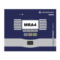
SEG HighPROTEC MRA4
User Manuals: Woodward SEG HighPROTEC MRA4 Relays
Manuals and User Guides for Woodward SEG HighPROTEC MRA4 Relays. We have
1
Woodward SEG HighPROTEC MRA4 Relays manual available for free PDF download: Device Manual
Woodward SEG HighPROTEC MRA4 Device Manual (510 pages)
Feeder Protection
Brand:
Woodward
| Category:
Protection Device
| Size: 14 MB
Table of Contents
Comments on the Manual
11
Information Concerning Liability and Warranty
11
Important Definitions
12
Scope of Delivery
16
Device Planning
21
Device Planning Parameters of the Device
22
Installation and Connection
23
Installation Diagram
24
Assembly Groups
25
Digital Inputs
31
Current Measuring Inputs and Ground Current Measuring Input
35
Communication Interfaces
38
Protective Relay
38
Assignment of the Zero Modem Cable
42
Current Transformers (CT)
43
Current Transformer Connection Examples
43
Voltage Transformers
49
Navigation Operation
59
Basic Menu Control
64
Smart View Keyboard Commands
65
Installation of Smart View
66
Switching the Language of the Graphical User Interface
67
Setting up the Connection PC - Device
68
Set-Up a Connection Via Ethernet - TCP/IP
68
Set-Up a Connection Via Serial Interface under Windows 2000
69
Set up a Connection Via Serial Interface under Windows XP
71
Connected to the Device and Calling up Websites at the same Time
74
Establishing the Connection Via a USB-/RS232-Adapter
74
Smart View Persistent Connection Problems
77
Loading of Device Data When Using Smart View
77
Restoring of Device Data When Using Smart View
78
Backup and Documentation When Using Smart View
79
Printing of Device Data When Using Smart View (Setting List)
79
Saving Data as a Txt-File Via Smart View
79
Offline Device Planning Via Smart View
80
Measuring Values
81
Read out Measured Values
81
Read out of Measured Values Via Smart View
81
Global Parameters of the Energy Counter Module
85
Direct Commands of the Energy Counter Module
85
Read out Statistics
87
Statistics to be Read-Out Via Smart View
87
Statistics (Configuration)
88
Statistics (Configuration) Via Smart View
88
Direct Commands
89
Global Protection Parameters of the Statistics Module
94
States of the Inputs of the Statistics Module
95
Signals of the Statistics Module
95
Counters of the Module Statistics
95
Manual Acknowledgment Via Smart View
98
External Acknowledgments
99
External Acknowledge Via Smart View
99
Manual Resets Via Smart View
100
Assignment List
101
Status Display Via Smart View
126
Optional Digital Inputs
133
Binary Output Relays
137
System Contact
139
Light Emitting Diodes (Leds)
161
The »System OK« LED
164
Global Protection Parameters of the LED Module
165
LED Module Input States
178
Operating Panel (HMI)
183
Special Parameters of the Panel
183
Direct Commands of the Panel
183
Global Protection Parameters of the Panel
183
Read out Disturbance Records
187
Deleting Disturbance Records
188
Deleting Disturbance Records Via Smart View
188
Special Parameters of the Disturbance Recorder
192
Read out the Fault Recorder
194
Read out the Fault Recorder Via Smart View
194
Read out the Event Recorder
199
Read out the Event Recorder Via Smart View
199
Modbus ® Protocol Configuration
203
Modbus RTU
204
Modbus TCP
205
Direct Commands of the Modbus
206
Global Protection Parameters of the Modbus
206
Parameter Definitions
215
Device Planning Parameters
216
State of the Module Inputs
216
Operational Modes (Access Authorization)
220
Operational Mode - »Display Only
220
Operation Mode - »Parameter Setting and Planning
220
Password Entry at the Panel
221
Password Changes
221
Password Forgotten
221
Changing of Parameters - Example
222
Changing of Parameters When Using the Smart View - Example
223
Protection Parameters
225
Setting Groups
225
Setting Group Switch
225
Copying Setting Groups (Parameter Sets) Via Smart View
227
Comparing Setting Groups Via Smart View
227
Comparing Parameter Files Via Smart View
228
Converting Parameter Files Via Smart View
228
Field Parameters
229
Permanent Blocking
234
Temporary Blocking
234
Activate, Deactivate Respectively Block Temporarily Protection Functions
239
Module: Protection (Prot)
241
Direct Commands of the Protection Module
248
Global Protection Parameters of the Protection Module
248
Protection Module Input States
250
Protection Module Signals (Output States)
250
Protection Module Values
251
Device Planning Parameters of the I Module
277
Global Protection Parameters of the I Module
277
Setting Group Parameters of the I Module
279
I Module Input States
283
I Module Signals (Output States)
284
Global Protection Parameters of the Ground Fault Protection
304
Ground Fault Protection Input States
310
Ground Fault Protection Signals (Output States)
311
Device Planning Parameters of the Module External Protection
443
Global Protection Parameters of the Module External Protection
443
Module External Protection Input States
445
Module External Protection Signals (Output States)
445
Commissioning: External Protection
446
Device Planning Parameters of the Current Transformer Supervision
463
Global Protection Parameter of the Current Transformer Supervision
463
Setting Group Parameters of the Current Transformer Supervision
464
Current Transformer Supervision Input States
465
Current Transformer Supervision Signals (Outputs States)
465
Device Parameters
474
Synchronize Date and Time Via Smart View
474
Version Via Smart View
474
TCP/IP Settings
475
Direct Commands of the System Module
476
Global Protection Parameters of the System
477
System Module Input States
480
System Module Signals
481
Special Values of the System Module
482
Commissioning/Protection Test
484
Putting out of Operation - Plug out the Relay
485
Self Supervision
487
Error Messages / -Codes
488
Technical Data
489
Climatic Environmental Conditions
489
Routine Test
489
Voltage Supply
490
Power Consumption
490
Real Time Clock
490
Current and Earth Current Measurement
492
Voltage and Residual Voltage Measurement
492
Frequency Measurement
492
Supervision Contact (SC)
493
Time Synchronization IRIG
494
Front Interface RS232
494
Boot Phase
494
Design Standards
495
EMC Immunity Tests
496
EMC Emission Tests
497
Environmental Tests
498
Mechanical Tests
499
Real Time Clock Tolerances
500
Protection Stages Tolerances
502
Advertisement
Advertisement
Related Products
Woodward MRM4
Woodward MRA1
Woodward MRI3-ITE
Woodward MRN3-1
Woodward MRIK3-C
Woodward MRIK3
Woodward MRG3-IER
Woodward MRG3-U0
Woodward MRG3-M
Woodward MRG3-IU0-M
Woodward Categories
Controller
Control Unit
Relays
Control Systems
Industrial Equipment
More Woodward Manuals
Login
Sign In
OR
Sign in with Facebook
Sign in with Google
Upload manual
Upload from disk
Upload from URL