Sign In
Upload
Manuals
Brands
Woodward Manuals
Control Unit
9907-162
Woodward 9907-162 Manuals
Manuals and User Guides for Woodward 9907-162. We have
1
Woodward 9907-162 manual available for free PDF download: Installation And Operation Manual
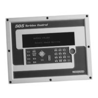
Woodward 9907-162 Installation And Operation Manual (176 pages)
Digital Governor for Steam Turbines with Single or Split-Range Actuators
Brand:
Woodward
| Category:
Control Unit
| Size: 1 MB
Table of Contents
Table of Contents
3
Electrostatic Discharge Awareness
7
Chapter 1. General Information
9
Introduction
9
General Description
11
Figure 1-1. Typical Single or Dual Inlet Steam Turbine
12
Figure 1-2. Split Range or Admission Type of Turbine Configuration
12
505 Inputs and Outputs
13
Control Overview
14
Figure 1-3A. Overview of 505 Functionality
15
Figure 1-3B. Overview of 505 Functionality
16
Speed Control
17
Auxiliary Control
17
Load Sharing Input
18
Cascade Control
18
Valve Limiter
18
Starting Features
19
Critical Speed Avoidance
19
Block Diagrams
20
Figure 1-4. Overview of 505 Functionality Notes
20
Figure 1-5. Single or Split-Range Turbine Configurations
21
Figure 1-6. Single or Split-Range Turbine Configurations
21
Keypad and Display
22
Figure 1-7. Single or Split-Range Turbine Configurations
22
Figure 1-8. 505 Key Pad and Display
22
Watchdog Timer/Cpu Fault Control
24
Chapter 2. Installation Procedures
25
Introduction
25
Mechanical Data and Hardware Installation
25
Figure 2-1. 505 Control Layout (Standard Enclosure)
27
Figure 2-2. 505 Bulkhead-Mounted Enclosure
28
Figure 2-3. Jumper Options
29
Figure 2-4. Jumper Locations
29
Figure 2-5. Cageclamp Terminal Blocks
31
Figure 2-6. Control Wiring Diagram
32
Figure 2-7. Representative 505 I/O Schematic
33
Figure 2-8. Fuse Location
34
Figure 2-9. Shielded Wire Connections
35
Figure 2-10. Typical RS-232 Communications
40
Figure 2-11. Typical RS-422 Communications
40
Communications Grounding and Shielding
41
Figure 2-12. Typical RS-485 Communications
41
Figure 2-13. Preferred Multipoint Wiring with a Separate Signal Ground Wire
41
Figure 2-14. Alternate Multipoint Wiring Without a Separate Signal Ground
42
Chapter 3. 505 Control Description
43
Introduction
43
Turbine Start
43
Figure 3-1. Basic Control Overview
43
Turbine Start Modes
45
Figure 3-2. Manual Start Mode Example
46
Figure 3-3. Semiautomatic Start Mode Example
47
Critical Speed Avoidance
48
Figure 3-4. Automatic Start Mode Example
48
Idle/Rated
49
Automatic Start Sequence
50
Figure 3-6. Automatic Start Sequence
51
No Idle Programmed
53
Speed Control Overview
53
Speed PID Operational Modes
54
Figure 3-7. Speed Control Functional Diagram
54
Figure 3-8. Speed PID Control Modes
55
Figure 3-9. Frequency and Unit Load Relationship
57
Figure 3-10. Speed Relationships
59
Figure 3-11. Loadsharing Logic
65
Cascade Control
66
Figure 3-12. Cascade Functional Diagram
67
Auxiliary Control
72
Figure 3-13. aux Control Overview
72
Remote Auxiliary Setpoint
76
Valve Limiter
78
Emergency Shutdown
78
Controlled Shutdown
79
Overspeed Test Function
80
Local/Remote Function
81
Function Keys
82
Relays
82
Chapter 4. Configuration Procedures
85
Program Architecture
85
Figure 4-1. Basic Program Architecture
85
Programming the 505
86
Figure 4-2. Initial 505 Program Mode Entry
86
Figure 4-3A. Program Mode Blocks
89
Figure 4-3B. Program Mode Blocks
90
Figure 4-3C. Program Mode Blocks
91
Figure 4-3D. Program Mode Blocks
92
Exiting the Program Mode
109
Figure 4-4. Exiting the Program Mode
109
Valve/Actuator Calibration & Test
113
Calibration/Stroking Procedure
114
Calibration/Stroking Procedure
116
Figure 4-5. Stroke Actuator
118
Figure 4-6. Stroking Dual Actuators
119
Chapter 5. 505 Operation
120
Run Mode Architecture
120
Figure 5-1. Basic Program Architecture
120
Figure 5-2A. Overview of Run Mode
121
Figure 5-2B. Overview of Run Mode
122
Figure 3-5. Idle/Rated Start
123
Keypad and Display
124
Run Mode Front Panel Keys
124
Figure 5-3. 505 Keypad and Display
124
Starting Procedures
125
Speed Key Screens
126
Figure 5-4. SPEED Key Screens
126
Figure 5-5. Direct Setpoint Entry
129
Overspeed Test Function
130
Figure 5-6. Overspeed Test Enable Key Screens
130
F3 and F4 Keys
131
Limiter (LMTR) Key Screens
131
Actuator (ACTR) Key Screens
132
Figure 5-7. LMTR Key Screens
132
Control (CONT) Key Screens
133
Dynamics (DYN) Key Screens
135
Stop Key Screens
136
Auxiliary (Aux) Key Screens
136
Remote/Speed Bias (RMT) Key Screens
139
Unit Load (KW) Key Screens
142
Cascade (CAS) Key Screens
143
Alarms
145
Trips
146
Speed, Cascade, and Auxiliary Dynamics Adjustments
147
Chapter 6. Communications
151
Modbus Communications
151
Port Adjustments
154
505 Control Modbus Addresses
154
Specific Address Information
165
Chapter 7. Service Options
167
Product Service Options
167
Woodward Factory Servicing Options
168
Returning Equipment for Repair
169
Replacement Parts
169
Engineering Services
170
How to Contact Woodward
170
Technical Assistance
171
Appendix . 505 Program Mode Worksheets
172
Declarations
175
Advertisement
Advertisement
Related Products
Woodward 9907-175
Woodward 9907-198
Woodward 9907-163
Woodward 9907-164
Woodward 9907-838
Woodward 9907-252
Woodward 9907 Series
Woodward 9907-018
Woodward 9907-019
Woodward 9907-024
Woodward Categories
Controller
Control Unit
Relays
Control Systems
Industrial Equipment
More Woodward Manuals
Login
Sign In
OR
Sign in with Facebook
Sign in with Google
Upload manual
Upload from disk
Upload from URL