Sign In
Upload
Manuals
Brands
Woodward Manuals
Protection Device
8237-2600
Woodward 8237-2600 Manuals
Manuals and User Guides for Woodward 8237-2600. We have
1
Woodward 8237-2600 manual available for free PDF download: Product Manual
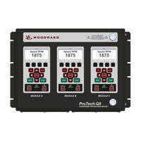
Woodward 8237-2600 Product Manual (195 pages)
with Math Enhancements
Brand:
Woodward
| Category:
Protection Device
| Size: 6 MB
Table of Contents
Table of Contents
3
Warnings and Notices
10
Electrostatic Discharge Awareness
11
Regulatory Compliance
12
Acronyms and Definitions
15
Chapter 1. General Information
16
Purpose and Scope
16
How to Use this Manual
16
Description
16
Applications
17
Figure 1-1. Typical Protech-GII Application (Voted Trip Relay Models)
18
Figure 1-2. Typical Protech-GII Application (Independent Trip Relay Models)
18
What's New
19
Figure 1-3. Typical Gas Turbine Application (Voted Trip Relay Models)
19
Chapter 2. Installation
21
Introduction
21
Unpacking
21
Hardware Installation Procedure
21
Enclosures
22
Figure 2-1. Typical Protech-GII Bulkhead Package-Front View
22
Figure 2-2A. Typical Protech-GII Bulkhead Package-Front Door Open
23
Figure 2-2B. Bulkhead Schematic Showing Front Panel a Connection to Module a and Front Panel C Connection to Module C-Top View
23
Figure 2-3. Mounting Outline Diagram for Bulkhead-Mounted Models
24
Module Removal and Installation-Bulkhead Mount Package
25
Figure 2-4A. Typical Protech-GII Panel Mount Package-Front View
28
Figure 2-4B. Typical Protech-GII Panel Mount Package-Rear View with Cover
28
Figure 2-4C. Typical Protech-GII Panel Mount Package-Rear View Without Cover Showing Module
29
Figure 2-4D. Panel Mount Schematic Showing Front Panel a Connection to Module a and Front Panel C Connection to Module C-Top View
29
Figure 2-5A. Mounting Outline Diagram for Panel-Mount Models
30
Figure 2-5B. Mounting Outline Diagram for Panel-Mount Models
31
Figure 2-5C. Panel Cutout Diagram for Panel-Mount Models
32
Module Removal and Installation-Panel Mount Package
33
Mounting Location Considerations
34
Power Supply Requirements
35
Input/Output Specifications
37
Shielded Wiring
40
Control Wiring Guidelines
40
Figure 2-6. Screw Connection Terminal Block
41
Figure 2-7. Inside View of Protech-GII
42
Figure 2-8. Protech-GII Control Wiring Diagram
43
Figure 2-9. Trip Module-Included Within Voted Trip Relay Units Only
44
Figure 2-10A. Power Supply Field Wiring Routing & Stress Relief Diagram
44
Figure 2-10B. I/O Wiring Routing & Stress Relief Diagram
45
Figure 2-10C. Relay Output Field Wiring Routing & Stress Relief Diagram
45
Figure 2-11A. Example MPU (Passive Magnetic Pickup Unit) Wiring
46
Figure 2-11B. Example Proximity Probe (Active Magnetic Pickup Unit) Wiring (Internal Power)
47
Figure 2-11C. Example Proximity Probe (Active Magnetic Pickup Unit) Wiring (External Power, Non-Preferred)
47
Figure 2-11D. Example Eddy Current Probe (Active Magnetic Pickup Unit) Wiring
47
Figure 2-12A. Example Standard Discrete Input Wiring (Internal Power Option)
48
Figure 2-12B. Example Standard Discrete Input Wiring (External Power Option)
48
Figure 2-13. Example Analog Output Wiring
49
Figure 2-14A. Example Trip Relay Output Wiring
49
Figure 2-14B. Example Trip Relay Wiring (Per Module) (Independent Trip Relay) (Internal Supply)
50
Figure 2-14C. Example Trip Relay Wiring (Per Module) (Independent Trip Relay) (External Supply)
50
Figure 2-14D. Example Trip Relay Wiring (Voted Trip Relay Models)
51
Figure 2-14E. Example Alarm Relay Wiring (Internal Supply)
51
Chapter 3. Functionality
52
Introduction
52
Features
52
Figure 3-1. Module Diagram Without Speed Redundancy Manager Configured
53
Figure 3-2. Module Diagram with Speed Redundancy Manager Configured
54
Product Models
55
Figure 3-3. Basic Functional Overview of Independent Trip Relay Models
55
Figure 3-4. Functional Diagram of Single Protech-GII Module with Independent Trip Relay Outputs
56
Figure 3-5. Example TMR Trip Block Assembly Interface
57
Figure 3-6. Basic Functional Overview of Voted Trip Relay Models
58
Figure 3-7. Functional Diagram of Single Protech-GII Module with Voted Trip Relay Outputs
59
Figure 3-8. Simplex Trip Block Assembly
60
Inputs and Outputs
61
Figure 3-9. Dual Redundant Trip Block Assembly
61
Overspeed and Over-Acceleration Detection Logic
63
Figure 3-10. Over-Acceleration Enabling Diagram
64
Speed Diagnostics
66
Start Logic
66
Figure 3-11. Start Logic Diagram
67
Figure 3-12. Speed Fail Trip Diagram
67
Test Routines
68
Figure 3-13. Speed Fail Timeout Trip Diagram
68
Alarm and Trip Latches
70
System Logs
72
Protech-GII Response Time Performance
73
Figure 3-14. Total System Response Time Based on Sensed Frequency Level for Independent Trip Relay Models When Speed Redundancy Manager Function Is Not Configured
73
Figure 3-15. Total System Response Time Based on Sensed Frequency Level for Independent Trip Relay Models When Speed Redundancy Manager Function Is Configured
74
Figure 3-16. Total System Response Time Based on Sensed Frequency Level for 2Oo3 Voted Trip Relay Models When Speed Redundancy Manager Function Is Not Configured
74
Figure 3-17. Total System Response Time Based on Sensed Frequency Level for 2Oo3 Voted Trip Relay Models When Speed Redundancy Manager Function Is Configured
75
Figure 3-18. Response Time Definition
75
Chapter 4. Front Panel Interface
76
Introduction
76
Figure 4-1. Protech-GII Front Panel
76
Screen Layout
77
Figure 4-2. Protech-GII Screen
77
Keypad Functions
78
Figure 4-3. Protech-GII Faceplate
78
Navigation
79
Figure 4-4. Home Screen (with Alarm)
79
Figure 4-5. Home Screen (with Trip)
79
Passwords
80
Figure 4-6. Password Entry Screen Example
80
Monitor Menu
81
Figure 4-7. Monitor Menu
81
Figure 4-8. Monitor Summary Screen Example
82
Figure 4-9. Monitor Trip Latch Screen Example
82
Figure 4-10. Monitor Alarm Latch Screen Example
83
Figure 4-11. Monitor Dedicated Discrete Inputs Screen Example
84
Figure 4-12. Monitor Speed Input Screen Example
85
Figure 4-13. Monitor Speed Redundancy Manager Screen Example
85
Figure 4-14. Monitor Acceleration Redundancy Manager Screen Example
86
Figure 4-15. Monitor Speed Fail Timer Screen Example
87
Figure 4-16. Monitor Speed Readout (Home) Screen Example
87
Figure 4-17. Monitor Shared Start Input Screen Example
88
Figure 4-18. Monitor Shared Reset Input Screen Example
88
Figure 4-19. Monitor Shared Speed Fail Override Input Screen Example
89
Figure 4-20. Monitor Modbus Screen Example
89
Figure 4-21. Monitor/Set Date & Time Screen Example
90
Figure 4-22. Edit/Change Mode Active Screen Example
90
Figure 4-23. Highlight Time Field to Edit Screen Example
91
Figure 4-24. Ready to Apply Changes Screen Example
91
Figure 4-25. Monitor System Status
92
Figure 4-26. Monitor Module Information
92
View Logs
93
Figure 4-27. Logs Menu Screen Example
93
Figure 4-28. Overspeed/Over-Acceleration Log Screen Example
93
Figure 4-29. Trip Log Screen Example
94
Figure 4-30. Alarm Log Screen Example
94
Figure 4-31. Peak Speed/Acceleration Log Screen Example
95
Figure 4-32. Reset Logs Screen Example
95
Chapter 5. Configuration Using the Front Panel
96
Introduction
96
Editing Configuration Settings from the Front Panel
97
Configure Menu Page
97
Figure 5-2. Configure Menu Screen Example
97
Configuration Procedure
98
Figure 5-3. Save Configuration Screen Example
99
Figure 5-4. Configure Display Screen Example
99
Figure 5-5. Configure Speed Submenu Screen Example
100
Figure 5-6. Configure Speed Input Screen Example
101
Figure 5-7. Configure Acceleration Screen Example
102
Figure 5-8. Configure Start Logic
102
Figure 5-9. Configure Speed Redundancy Manager Screen Example
103
Figure 5-10. Configure Acceleration Redundancy Manager Screen Example
104
Figure 5-11. Configure Trip Latch Screen Example
104
Figure 5-12. Configure Alarm Latch Screen Example
105
Figure 5-13. Configure Dedicated Discrete Submenu Screen Example
105
Figure 5-14. Configure Start Input Sharing Screen Example
106
Figure 5-15. Configure Reset Input Sharing Screen Example
106
Figure 5-16. Configure Speed Fail Override Input Sharing Screen Example
107
Figure 5-17. Configure Test Modes Screen Example
107
Figure 5-18. Configure Auto-Sequence Test Screen Example
108
Figure 5-19. Configure Modbus Screen Example
109
Figure 5-20. Configure Power Supply Alarms Screen Example
109
Figure 5-21. Configuration Management Menu Screen Example
110
Figure 5-22. Configuration Overview Screen Example
110
Figure 5-23. Configuration Compare Screen Example
111
Figure 5-24. Configuration Copy Screen Example
112
Figure 5-25. Configuration Copy Screen Example
113
Figure 5-26. Password Change Screen Example
113
Chapter 6. Test Routines
115
Test Modes Menu
115
Temporary Overspeed Setpoint Test
115
Figure 6-1. Test Modes Menu
115
Figure 6-2A. Temporary Overspeed Test Screen Example
115
Figure 6-2B. Temporary Overspeed Test Screen Examples
117
Manual Simulated Speed Test
118
Figure 6-3. Manual Simulated Speed Test Screen Example
118
Figure 6-4. Test Frequency Resolution
119
Figure 6-5. Manual Simulated Speed Test Screen Example
119
Auto Simulated Speed Test
120
Figure 6-6. Auto Simulated Speed Test Screen Example
120
Auto-Sequence Test
122
Figure 6-7. Auto Sequence Test (Periodic Test Timer Enabled) Screen Example
122
Lamp Test
124
General Testing Notes
124
Figure 6-8. Lamp Test
124
Chapter 7. Programming and Configuration Tool (Pct)
125
General
125
Installation of the PCT
125
Figure 7-1 Website Search Results
125
PCT Levels of Operation
126
Figure 7-2. Host Computer Control Panel Display Settings
126
Using the PCT
127
Figure 7-4. Protech-GII PCT Off-Line Window
127
Figure 7-5. Button Status (Connected)
128
Figure 7-6. Button Status ( Not Connected)
128
Figure 7-7. Information Status Bar (Not Connected)
128
Figure 7-8. Information Status Bar Example (Connected)
128
Figure 7-9. Protech-GII PCT Off-Line Window
129
Figure 7-10. Status Bar and Button Status before Connection
129
Figure 7-11. PCT Connect Options Window
130
Figure 7-12. Status Bar and Button Status after Connection
130
Figure 7-13. PCT Security Log-In Window
130
Figure 7-14. Drop-Down Menu "Settings
131
Figure 7-15. Prompt to Set Settings File Default Values
132
Figure 7-16. Prompt for Settings File to Modify
132
Figure 7-17. Prompt to Connect
133
Figure 7-18. Prompt for Settings File to Edit
133
Figure 7-19. Prompt for Settings File to Load
134
Figure 7-20. Configuration Error
135
Figure 7-21. Compare Settings File Differences
135
Figure 7-22. Settings File Differences
135
Figure 7-23. PCT On-Line Window
136
Figure 7-24. Edit/View Configuration On-Line Window Example
137
Figure 7-25 Valid Range Display for Sudden Speed Loss Threshold Setting
138
Figure 7-26 Options Displayed When no Changes Are Detected
138
Figure 7-27 Options Displayed When Changes Are Detected
138
Figure 7-28 Incorrect Log-In Level
139
Figure 7-29 Configuration Error
139
Figure 7-30 Module Is Not Tripped
139
Figure 7-31. Configuration Error Log Example
140
Figure 7-32. Trip and Alarm Log Example
141
Figure 7-33. Overspeed/Acceleration Log Example
142
Figure 7-34. Module Faults Log Example
143
Chapter 8. Configuration Using the Pct
144
Introduction
144
Configuration Settings
145
Figure 8-1. Protech-GII PCT "Edit/View Configuration" Screen (Connected)
145
Input Configuration
147
Figure 8-2. Speed and Acceleration Configuration Example
147
Figure 8-3. Input Sharing Selection Configuration Example
150
Figure 8-4. Modbus Configuration Example
151
Functions Configuration
152
Figure 8-5. Test Modes Configuration Example
152
Figure 8-6. Start Logic & Power Supply Alarms Configuration Example
154
Figure 8-7. Other Outputs Configuration Example
155
Configuration Checks
156
Error Messages
157
Figure 8-8. Configuration Error Window
157
Figure 8-9. Data Entry Range Error Example
157
Chapter 9. Modbus Communications
158
Introduction
158
Monitor Only
158
Monitor and Control
158
Modbus Interface
159
Port Adjustments
159
Protech-GII Parameter Addresses
159
Chapter 10. Safety Management
165
Product Variations Certified
165
Safe State
165
SIL Specifications
165
Failure Rate Data
166
Response Time Data
166
Limitations
166
Management of Functional Safety
166
Restrictions
167
Competence of Personnel
167
Operation and Maintenance Practice
167
Installation and Site Acceptance Testing
167
Functional Testing after Initial Installation
167
Functional Testing after Changes
167
Proof Testing (Functional Test)
167
Chapter 11 Troubleshooting
169
Introduction
169
Chapter 12. Product Support and Service Options
176
Product Support Options
176
Product Service Options
176
Returning Equipment for Repair
177
Replacement Parts
178
Engineering Services
178
Contacting Woodward's Support Organization
178
Technical Assistance
179
Chapter 13. Asset Management
180
Product Storage Recommendations
180
Refurbishment Period Recommendation
180
Appendix A. Modbus Ethernet Gateway Information
181
Introduction
181
B&B Electronics Setup
181
Figure A-1. Wiring
182
Figure A-2. RS-485 2-Wire
182
Figure A-3. Network Settings
183
Figure A-4. Modbus TCP Settings
183
Figure A-5. Serial Communication Settings
184
Figure A-6. Serial Modbus Settings
184
Lantronix Setup
185
Figure A-7. RS-232 Wiring
185
Figure A-8. RS-285 2-Wire Wiring
186
Figure A-9. Overview
187
Figure A-10. Network Menu
187
Figure A-11. Serial Settings Menu
188
Figure A-12. Modem Control Menu
188
Figure A-13. Advanced Menu
189
Appendix B. Protech-GII Configuration Worksheet
190
Revision History
193
Advertisement
Advertisement
Related Products
Woodward 8237-2594
Woodward 8237-2598
Woodward 8237-2595
Woodward 8237-2599
Woodward 8237-2596
Woodward 8237-2597
Woodward 8237-2601
Woodward MicroNet 8237-1376
Woodward MicroNet 8237-1375
Woodward ProTech-GII 8237-1601
Woodward Categories
Controller
Control Unit
Relays
Control Systems
Industrial Equipment
More Woodward Manuals
Login
Sign In
OR
Sign in with Facebook
Sign in with Google
Upload manual
Upload from disk
Upload from URL