Sign In
Upload
Manuals
Brands
Woodward Manuals
Controller
8200-1300
Woodward 8200-1300 Manuals
Manuals and User Guides for Woodward 8200-1300. We have
1
Woodward 8200-1300 manual available for free PDF download: Product Manual
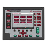
Woodward 8200-1300 Product Manual (138 pages)
Digital Control for Steam Turbines
Brand:
Woodward
| Category:
Controller
| Size: 4.4 MB
Table of Contents
Table of Contents
3
Warnings and Notices
7
Electrostatic Discharge Awareness
8
Introduction
9
Volume
9
Chapter 1. Service Tools
10
Overview
10
Control Assistant (CA)
10
Servlink-To-OPC-Server (SOS)
10
Appmanager (Appman)
10
Chapter 2. Peripheral Devices
11
Overview
11
DSLC-2 (Generator Synchronizer and Load Control)
11
Figure 2-1. DSLC-2
11
Figure 2-2. Configuration/Woodward Links/Dslc-2
12
Figure 2-3. Service Screen - DSLC-2 Power Parameters
12
Varistroke II (Electro-Hydraulic Actuator)
13
Figure 2-4. Service Screen - DSLC-2 Status Parameters
13
Figure 2-5. VS-II
13
Figure 2-6. Configuration/Woodward Links/Vs-II
14
Figure 2-7. Service/Varistroke II
14
MFR300 (Multi-Function Relay)
15
Protection/Breaker Control Relay)
15
Servo Position Controller (SPC)
15
Figure 2-8. Multi-Function Relay
15
Figure 2-9. LS-5
15
Figure 2-10. Servo Position Controller
16
Figure 2-11. Interface to Servo Position Controller
16
Real Power Sensor
17
Figure 2-12. Real Power Sensor
17
Engine Generator Control Package/Load Sharing (EGCP-3 LS)
18
Figure 2-13. EGCP-3 Control
19
Figure 2-14. EGCP-3 LS Functional Diagram
19
Figure 2-15. EGCP-3 LS Interface Wiring
20
Applying the 505 with Redundant I/H or I/P Converters
21
Figure 2-16. Typical Redundant I/H System with a Transfer Valve
21
Figure 2-17. Typical Redundant I/P System with a Pressure Selecting Relay Valve
22
Chapter 3. Application Notes
23
Overview
23
Example Applications
24
Figure 3-1. Pump or Compressor Discharge Pressure Control with Turbine Inlet Pressure Limiting
26
Figure 3-2. Inlet Pressure Control with Automatic Synchronizing & Generator Power Limiting
29
Figure 3-3. Exhaust Pressure Control with Generator Power Limiting and Plant Import/Export Limiting
33
Figure 3-4. Plant Import/Export Control with DRFD Servo Interface
38
Figure 3-5. Inlet Pressure Control with Isochronous Loadsharing Control in Island Mode
42
Figure 3-6. Import/Export Control or Exhaust Pressure Control with Isoch Load Sharing in Island Mode
45
Chapter 4. Operator Interface
50
Introduction
50
Graphical Display and Key Inputs
50
Figure 4-1 505 Keypad and Display
50
Service Panel Modes and User Levels
51
Chapter 5. Service Menu Procedures
53
Overview
53
Using the Service Menus
53
Figure 5-1. User Login for Service
53
Figure 5-2. Authorized and Unauthorized Components
54
Figure 5-3 Service Menu
55
Figure 5-4 Service Menu
55
Service Mode Parameters
58
Chapter 6. Understanding Pid Settings
80
Overview
80
Proportional Response
81
Figure 6-1. Proportional Gain Setting Effects
81
Figure 6-2. Open Loop Proportional and Integral Response
82
Proportional + Integral (Closed Loop)
83
Figure 6-3. Closed Loop Proportional and Integral Response
83
Derivative Response
84
Figure 6-4. Integral Gain (Reset) Setting Responses
84
Proportional + Derivative (Closed Loop)
85
Figure 6-5. Closed Loop Proportional and Derivative Action
86
Figure 6-6. Derivative Setting Effects
86
Proportional + Integral + Derivative (Closed Loop)
87
Figure 6-7. Closed Loop Proportional, Integral and Derivative Action
87
Controller Field Tuning General
88
Figure 6-8. Typical Response to Load Change
89
Chapter 7. Hardware/Operating System Faults
91
General
91
Wiring Problems
91
Control Adjustments
92
Other Operating Problems
92
505 Design Specifications
93
A Ppendix A. 505 D Esign S Pecifications
93
505 Service Mode Worksheet
94
Hardware Specifications
93
Software Specifications
93
Appendix C. Password Information
104
General
104
Monitor User Level
104
Operator User Level Password
104
Service User Level Password
104
Configure User Level Password
104
Serviceuser Mode Password
104
Appendix D. Servlink-To OPC Server (SOS) Tool
105
Figure D-1. SOS
105
Installing SOS
105
SOS Communication Link
105
Connecting a Pc/Laptop to the Control
106
Figure D-2. SOS Install Window
106
Figure D-3. SOS Server Status Dialog Box
106
Figure D-4. SOS - New Session Box
107
Figure D-5. SOS - Enter 505 TCP/IP Address
107
Figure D-6. SOS - Active Links Dialog Box
107
Appendix E. Control Assistant-Software Interface Tool
108
Features of Control Assistant
108
Figure E-1. Control Assistant License Agreement
108
Installing Control Assistant
108
Figure E-2. Control Assistant Install Window
109
Figure E-3. Control Assistant Folder Selection
109
Figure E-4. Control Assistant Install Complete
109
Figure E-5. Install Restart Window
110
Figure E-6. Control Assistant Window
110
Using Control Assistant
110
Figure E-7. Dialog for Servlink OPC Connection
111
Figure E-8. Winpanel Session
111
Figure E-9. Control Assistant - Retrieve Tunable Dialog Box
112
Figure E-10. Control Assistant - Send Tunable Dialog Box
113
Figure E-11. Control Assistant - Speed Control Trend Script
114
Figure E-12. Control Assistant - Create Trend Script File
115
Appendix F. Appmanger Service Tool
116
Figure F-1. App Manager Install Window
116
File Management with App. Manager
116
Installing App Manager
116
Figure F-2. App Manager License Agreement Window
117
Figure F-3. App Manager Installation
117
Figure F-4. App Manager Install Complete
117
Figure F-5. Appmanager Window
118
Figure F-6. Dialog for App Manager Connection
118
Figure F-7. App Manager Connected to a Control
119
Figure F-8. Appmanager Control Info Window
119
Figure F-10. Appmanager GUI Application Panel
120
Figure F-9. Appmanager Control (GAP) Application Panel
120
Figure F-11. Retrieving Files
121
Appendix G. Configuring Network Tcp/Ip Addresses
123
Figure G-1. Configuration/Communications Screen
123
Figure G-2. Ethernet Port Layout (Ports on Side)
123
Appendix H. Remoteview Tool
125
Figure H-1. Window Shown When the Time Limit Is Exceeded
125
Figure H-2. Installation Welcome Window
125
Figure H-3. Installation Folder Window
126
Figure H-4. Installation License Agreement Window
126
Figure H-5. Installation Start Menu Shortcuts Window
127
Figure H-6. Installation Ready to Install Window
127
Figure H-7. Installation Complete Window
128
Figure H-8. Entering an IP Address to be Added to the Control List
129
Figure H-9. Control Selected in the Control List
129
Figure H-10. Login Window with Fields for User Name and Password
130
Figure H-11. an Application Selected in the Application List
131
Figure H-12. Default View of the Tool
132
Figure H-13. Simple View of the Tool
132
Figure H-14. Full View of the Tool
133
Figure H-15. Entering a Name for the Current Settings
133
Figure H-16. a New Settings File Entered in the Predefined Settings List
134
Figure H-17. Remote View Tool (Default Setting) after Opening from the Configuration Window
135
Appendix I. Using 505 Internal Simulation Mode
136
Figure I-1. HW Simulation Mode Access
136
Appendix J. Custom Tag Name Procedure
137
Required Tools
137
Creating Custom Tags
137
Advertisement
Advertisement
Related Products
Woodward 8200-1301
Woodward 8200-1302
Woodward 8200-1500
Woodward 8200-1501
Woodward 8200-1506
Woodward 8200-1502
Woodward 8200-1508
Woodward 8200-1503
Woodward 8200-1505
Woodward 8200-1509
Woodward Categories
Controller
Control Unit
Relays
Control Systems
Industrial Equipment
More Woodward Manuals
Login
Sign In
OR
Sign in with Facebook
Sign in with Google
Upload manual
Upload from disk
Upload from URL