Sign In
Upload
Manuals
Brands
Woodpecker Manuals
Planer
ADH 5-410
Woodpecker ADH 5-410 Manuals
Manuals and User Guides for Woodpecker ADH 5-410. We have
1
Woodpecker ADH 5-410 manual available for free PDF download: Operating Manual
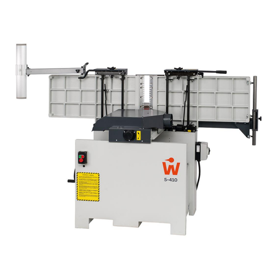
Woodpecker ADH 5-410 Operating Manual (54 pages)
Combined Surface Planer & Thicknesser
Brand:
Woodpecker
| Category:
Planer
| Size: 2 MB
Table of Contents
Table of Contents
2
Introduction
6
Legal Notice
6
Figures
6
Symbols
6
General Symbols
6
Figure 1: ADH 5-410 in Surface Planing Mode
6
Symbols in Safety Instructions
7
General
8
Target Group and Previous Experience
8
Requirements for the Operators
8
Accident Prevention
8
General Safety Regulations
9
Standard Equipment
10
Options, Accessories and Spare Knives
10
Safety
11
Basic Safety Instructions
11
Application Area and Intended Use
11
Modifications and Conversions to the Machine
11
Residual Risks
12
Observe the Environmental Protection Regulations
13
Organisational Measures
13
Personnel Selection and Qualification - Basic Duties
13
Training of Personnel
14
Safety Instructions for Specific Phases of Operation
14
Normal Operation
14
Special Work Within the Scope of Maintenance Work as Well as Troubleshooting in the Workflow
15
Safe Working Practices
16
Construction-Related Safety Devices
16
Electrical Safety Devices
17
Hazardous Areas
18
Danger Zones During Surface Planing
18
Working Areas & Protective Measures
18
Figure 2: Danger Zones During Surface Planing
18
Danger Zones During Thicknessing
19
Working Areas & Protective Measures
19
Figure 3: Danger Zones During Thicknessing
19
Machine Data
20
Technical Specifications
20
Correspondence in the Case of Service
20
Figure 4: Name Plate
20
Emission Levels
21
Noise Information
21
Noise Emission Values
21
Workplace Requirements
21
Figure 5: Working Areas
21
Dimensions
22
Figure 6: Dimensions
22
Installation and Connection
23
Check Delivery Conditions
23
Transport
23
Unloading with a Forklift Truck
23
Setting down with a Forklift Truck
23
Figure 7: Unloading with a Forklift Truck
23
Figure 8: Setting down with a Forklift Truck
23
Unloading and Setting down with Overhead Crane
24
Machine Installation
24
Figure 9: Unloading / Setting down with Crane
24
Figure 10: Remove Transport Straps
24
Temporary Storage
25
Lashing on a Transport Vehicle
25
Connecting the Extraction Unit
26
Automatic Switching of the Extraction System (Option)
26
Convert Chip Collector
26
Figure 11: Chip Collector in "Surface Planing" Position
26
Figure 12: Chip Collector in "Thicknessing" Position
26
Electrical Connections
27
Supply Cable and External Fuse Protection
27
Figure 13: Main Switch Housing
27
Machine Overview
28
Main Components 1
28
Figure 14: Machine Overview - Main Components 1
28
Main Components 2
29
Figure 15: Machine Overview - Main Components 2
29
Machining Options
30
Surface Planing
30
Jointing
30
Thickness Planing
30
Figure 16: Surface Planing
30
Figure 17: Jointing
30
Figure 18: Thickness Planing
30
Workpiece Requirements
31
Machining as a Surface Planer & Jointer
31
Machining as a Thickness Planer
31
Operating the Machine
32
Switching the Machine on and off
32
Control Switches
32
Switching on
32
Switching off
32
Figure 19: Control Switches
32
Operating Mode Surface Planing & Jointing
33
Operating Elements for Surface Planing & Jointing
33
Figure 20: Operating Elements During Planing & Jointing
33
Conversion from Thicknesser to Surface Planer & Jointer
34
Surface Planing and Jointing: Preparation and Guidelines
34
Figure 21: Locking Springs for Planing Tables
34
Surface Planing of Workpieces up to 65 MM Thickness
35
Figure 22: Surface Planing Preparation
35
Figure 23: Planing up to 65 MM (1)
35
Figure 24: Planing up to 65 MM (2)
35
Figure 25: Planing up to 65 MM (3)
35
Jointing of Workpieces up to 65 MM Thickness
36
Surface Planing of Workpieces over 65 MM Thickness
36
Jointing of Workpieces over 65 MM Thickness
36
Figure 26: Jointing Preparation
36
Figure 27: Jointing up to 65 MM
36
Figure 28: Planing over 65 MM
36
Figure 29: Jointing over 65 MM (1)
36
Figure 30: Jointing over 65 MM (2)
36
Surface Planing and Jointing of Small Cross Sections (E.g. Strips)
37
Surface Planing of Short Workpieces
37
Jointing Short Workpieces
37
Surface Planing under Inclination or Bevelling
37
Figure 31: Jointing Small Cross-Sections
37
Figure 32: Planing Short Workpieces
37
Figure 33: Jointing Short Workpieces
37
Figure 34: Inclined Surface Planing
37
Safety Accessories for Small, Short or Narrow Workpieces
38
Adjusting the Parallelism of the Planing Tables
38
Figure 35: Self-Made Auxiliary Fence (Example)
38
Figure 36: Adjustment Screws on the Outfeed Table
38
Figure 37: Adjustment Screws on the Infeed Table
38
Operating Mode Thickness Planing
39
Operating Elements for Thickness Planing
39
Figure 38: Operating Elements for Thickness Planing
39
Conversion from Surface Planer & Jointer to Thicknesser
40
Thickness Planing Procedure
40
Figure 39: Suction Hose Position in Thickness Planing Mode
40
Figure 40: Display for Fine Adjustment of the Height
40
Safe Working on the Thicknesser
41
Figure 41: Thickness Planing
41
Changing the Planer Knives
42
Changing the Knives on Traditional Cutter Block
42
Cutter Block Setting Gauge
42
Figure 42: Traditional Cutter Block
42
Magnetic Quick Adjusters 1533 (Option)
43
Figure 43: Magnetic Quick Adjusters Type 1533
43
Figure 44: Adjusting the Cutter Block
43
Changing the Knives on Spiral Cutter Block (Option)
44
Procedure for Changing the Knives
44
Advantages of the Spiral Cutter Block
44
Service Set for Spiral Cutter Blocks
44
Figure 45: Indexable Inserts of the Spiral Cutter Block
44
Figure 46: Service Set for Spiral Cutter Blocks
44
Optional Components
45
Bridge Guard SUVAMATIC
45
Mobile Base
45
Pushing Devices and Feeding Aids
45
Figure 47: Bridge Guard SUVAMATIC
45
Figure 48: Mobile Base
45
Figure 49: Push Stick
45
Figure 50: Push Block
45
Figure 51: Push Handle
45
Figure 52: Infeed System
45
Troubleshooting
46
Maintenance and Inspection
47
Cleaning
47
Lubrication
47
Tensioning the V-Belts
48
Maintaining the V-Belts
48
Changing the V-Belts
48
Checking the Electronic Motor Brake
48
Figure 54: Tightening V-Belts
48
Checking the Anti-Kickback Fingers
49
Checking the Function of the Emergency Stop Button
49
Checking the Safety Labels
49
Taking the Machine out of Operation / Storage
49
Average Situations / Emergencies
49
Electrical Circuit Diagram
50
Figure 55: Electrical Circuit Diagram
50
Disassembly and Scrapping
51
Options and Accessories
52
Accessories for Traditional Cutter Blocks
52
Spiral Cutter Block
52
Accessories for Spiral Cutter Block
52
Optional Bridge Guard
53
TEC - Pushing Devices / Feeding Aids
53
Special Accessories
53
EU - Declaration of Conformity
54
Advertisement
Advertisement
Related Products
Woodpecker Ai-Motor
Woodpecker Ai Ray
Woodpecker AP-B
Woodpecker AP-H
Woodpecker AP-H Plus
Woodpecker Categories
Dental equipment
Medical Equipment
Media Converter
Thermometer
Saw
More Woodpecker Manuals
Login
Sign In
OR
Sign in with Facebook
Sign in with Google
Upload manual
Upload from disk
Upload from URL