Table of Contents
Advertisement
Quick Links
TRANSLATION OF THE ORIGINAL VERSION
Operating Manual
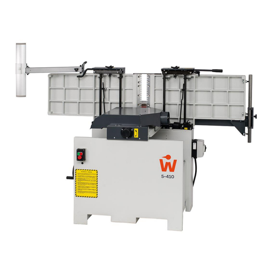
Combined Surface Planer & Thicknesser
WOOD
PECKER
ADH 5-410
ADH 5-410
Machine Type:
WOOD
PECKER
HOKUBEMA Maschinenbau GmbH
Graf-Stauffenberg-Kaserne, Binger Str. 28 | Halle 120
DE 72488 Sigmaringen | Tel. +49 07571 755-0
E-Mail:
info@ichbinwoodpecker.de
| Web:
https://www.ichbinwoodpecker.de
Advertisement
Table of Contents
Troubleshooting

Subscribe to Our Youtube Channel
Summary of Contents for Woodpecker ADH 5-410
- Page 1 TRANSLATION OF THE ORIGINAL VERSION Operating Manual Combined Surface Planer & Thicknesser WOOD PECKER ADH 5-410 ADH 5-410 Machine Type: WOOD PECKER HOKUBEMA Maschinenbau GmbH Graf-Stauffenberg-Kaserne, Binger Str. 28 | Halle 120 DE 72488 Sigmaringen | Tel. +49 07571 755-0 E-Mail: info@ichbinwoodpecker.de...
-
Page 2: Table Of Contents
Table of Contents Introduction ..............................6 Legal Notice ................................6 Figures ..................................6 Symbols ................................6 General Symbols ..............................6 Symbols in Safety Instructions ..........................7 General ................................8 Target Group and Previous Experience ........................8 Requirements for the Operators ..........................8 Accident Prevention .............................. - Page 3 Installation and Connection ......................... 23 Check Delivery Conditions ............................ 23 Transport ................................23 7.2.1 Unloading with a Forklift Truck ........................23 7.2.2 Setting down with a Forklift Truck ......................23 7.2.3 Unloading and setting down with Overhead Crane ..................24 Machine Installation .............................
- Page 4 10.2.13 Adjusting the Parallelism of the Planing Tables................... 38 10.3 Operating Mode Thickness Planing ........................39 10.3.1 Operating Elements for Thickness Planing ....................39 10.3.2 Conversion from Surface Planer & Jointer to Thicknesser ................40 10.3.3 Thickness Planing Procedure ........................40 10.3.4 Safe Working on the Thicknesser ........................
- Page 5 List of Figures Figure 1: ADH 5-410 in surface planing mode ............................6 Figure 2: Danger zones during surface planing ............................ 18 Figure 3: Danger zones during thicknessing ............................19 Figure 4: Name plate ................................... 20 Figure 5: Working areas ..................................21 Figure 6: Dimensions ...................................
-
Page 6: Introduction
Legal Notice WOODPECKER is a brand of Hokubema Maschinenbau GmbH. All contents of these operating instructions are subject to the rights of use and copyright of HOKUBEMA Maschinenbau GmbH. Any reproduction, modification, further use and publication in other electronic or printed media, as well as their online publication, requires the prior written consent of HOKUBEMA Maschinenbau GmbH. -
Page 7: Symbols In Safety Instructions
Symbols in Safety Instructions Symbol Safety Instruction General danger symbol, which requires the highest attention! Failure to observe may result in damage to the equipment, serious injury or even death. Warning of possible danger from forklift traffic! Non-observance may result in life-threatening injuries. Warning indicates a possible hazard under suspended loads! Non-observance may result in life-threatening injuries. -
Page 8: General
3 General This combined planer and thicknesser ADH 5-410 was produced according to the current state of the art and put into operation as a complete machine. All legal and normative regulations were complied with. • The machine has a surface planing width of 410 mm and a thickness planing width of 406 mm. -
Page 9: General Safety Regulations
General Safety Regulations In general, the following safety regulations and obligations apply when handling the planer & thicknesser: • A planer & thicknesser may only be operated in a technically perfect and clean condition. • It is prohibited to remove, modify or bypass any protective, safety or monitoring equipment. •... -
Page 10: Standard Equipment
3.5 Standard Equipment • Powerful three-phase motor 5.5 kW (7.5 HP) • Foldable bridge guard as cutter block cover • Manual adjustment of the feed table during surface planing via scale • Manual height adjustment of the thicknessing table via handwheel (with scale, fine adjustment to 0.1 mm via analogue display) •... -
Page 11: Safety
Safety Basic Safety Instructions Woodworking machines can be dangerous if used improperly. Therefore, observe the safety instructions listed in this chapter and the accident prevention regulations of your employer's liability insurance association! The manufacturer accepts no liability for damage and malfunctions resulting from failure to observe these operating instructions. -
Page 12: Residual Risks
4.1.3 Residual Risks The machine is built according to the latest state of the art and the recognised safety rules. Nevertheless, the use of the machine may cause danger to life and limb of the user or third parties or damage to the machine and other equipment. -
Page 13: Observe The Environmental Protection Regulations
4.1.4 Observe the Environmental Protection Regulations During all work with the machine, the environmental protection regulations, obligations and laws for waste avoidance and proper recycling and/or disposal applicable at the place of use must be observed. This applies in particular to installation, repair and maintenance work involving substances that could pollute the groundwa- ter (e.g. -
Page 14: Training Of Personnel
4.1.7 Training of Personnel All machine operators must be adequately trained in the operation and maintenance of the machine. In partic- ular, the training must include the following: • General rules for the use of the machine, proper operation, correct adjustment of the machine and sur- face planer fence as well as the use of other accessories (e. -
Page 15: Special Work Within The Scope Of Maintenance Work As Well As Troubleshooting In The Workflow
Machine condition: Check the machine for externally visible damage and defects at least once per shift! Any changes that have occurred (including those in the operating behaviour) must be reported immedi- ately to the responsible office or person! If necessary, stop and secure the machine immediately! Extraction: The machine must be connected to an effective extraction system. -
Page 16: Safe Working Practices
4.2.3 Safe Working Practices Wear personal protective equipment (safety goggles, safety shoes, hearing protection, dust mask)! Always work with all protective devices! These must be in the intended places and in perfect working order. Defective guards must be replaced immediately. Do not start planing until the motor / tool has reached full speed. -
Page 17: Electrical Safety Devices
• Anti-kickback fingers when operating as a thickness planer: This protection device against kickback is lo- cated on the infeed side in front of the feed roller of the thickness planer and covers the entire working width. The system consists of individual fingers that are mounted on a ø 20 mm shaft. The width of the fingers is 15 mm and the distance between the fingers is 6 mm. -
Page 18: Hazardous Areas
4.4 Hazardous Areas 4.4.1 Danger Zones during Surface Planing Danger Zone 2 Helper Danger Zone 1 Operator Figure 2: Danger zones during surface planing Danger Zone Type of hazard Prevention Danger of drawing in and cutting! 1. Never reach into the Danger Zone 1 when the cutter is The area around the cutter block is ... -
Page 19: Danger Zones During Thicknessing
4.4.3 Danger Zones during Thicknessing Danger Zone 3 Danger Zone 2 Helper Operator Obstacle Danger Zone 1 (e.g. wall etc.) Figure 3: Danger zones during thicknessing Danger Zone Type of hazard Prevention Danger of drawing in and cutting! Never reach into the opening of the thickness Although the cutter block is not accessible planer while the cutter is running or the ma- from the outside, it is theoretically possi-... -
Page 20: Machine Data
Machine Data Technical Specifications Planing width (planer/jointer): max. 410 mm Planing width (thicknesser): max. 406 mm Passage height: min. 4 mm / max. 225 mm Table height: 850 mm Table length (planer/jointer): 1800 mm Table length (thicknesser): 700 mm Chip removal (thicknesser): max. -
Page 21: Emission Levels
Emission Levels 5.3.1 Noise Information The values given are emission levels and therefore do not necessarily represent safe workplace values. Alt- hough there is a correlation between emission and immission levels, it cannot be reliably deduced whether additional precautionary measures are necessary or not. Factors that may affect the current immission level at the workplace include the duration of exposure, the nature of the workspace, other noise sources, etc., e.g. -
Page 22: Dimensions
6 Dimensions 1900 Figure 6: Dimensions Subject to design and dimensional changes! BA_WP_ADH5-410_EN_22-22.docx... -
Page 23: Installation And Connection
Installation and Connection Check Delivery Conditions Check the consignment for completeness and possible transport damage. In case of transport damage, please keep the packaging and inform the shipping company and the manufacturer immediately! Later complaints cannot be accepted. Transport Lifting and transporting the machine must be carried out by qualified persons who have the required experi- ence and equipment. -
Page 24: Unloading And Setting Down With Overhead Crane
7.2.3 Unloading and setting down with Overhead Crane • Prepare four tension belts or nylon slip ropes (C) with the re- quired load capacity and in sufficient length and hang them on the crane hook (D) as shown in Figure 9. •... -
Page 25: Temporary Storage
Temporary Storage If the machine is not put into operation immediately after delivery, it must be stored carefully in a protected place. Carefully cover the entire machine so that neither dust nor moisture can penetrate. The bare, non-surface-treated parts (e.g. the cast iron tabletop) are provided with a preservative. This must be checked regularly for effectiveness and renewed if necessary. -
Page 26: Connecting The Extraction Unit
Connecting the Extraction Unit • The machine must be connected to an effective extraction system on-site. Installation only by a qualified electrician! • The foldable chip collector has a suction nozzle with a diameter of 120 mm. • All parts of the extraction system, incl. hoses, must be included in the earthing measure. -
Page 27: Electrical Connections
Electrical Connections The connection must be carried out by an authorised electrician! You will find the electrical circuit diagram in the chapter 15. Please observe the specified nominal voltage 400 VAC / 50 Hz (3 phases / N / PE)! •... -
Page 28: Machine Overview
8 Machine Overview Main Components 1 Figure 14: Machine overview - main components 1 Description Description Surface planer fence Machine body Height adjustment bridge guard Main switch Swing-away arm clamping for bridge guard Height adjustment lever for infeed table Height adjustment of the outfeed table Height adjustment clamping infeed table Control unit with on/off switch &... -
Page 29: Main Components 2
Main Components 2 Figure 15: Machine overview - main components 2 Description Description Outfeed table (planer & jointer) Thickness planing table (thicknesser) Bridge guard (planer & jointer) Handwheel for passage height (thicknesser) Bridge guard clamping (planer & jointer) Clamping for height adjustment (thicknesser) Scale for chip removal (planer &... -
Page 30: Machining Options
9 Machining Options Do not perform machining operations on the machine that do not involve machining the entire length of the workpiece. Heavily curved workpieces that cannot rest well on the table tops of the surface planer and on the fence must not be machined. During operation as a thickness planer, workpieces with cross-sections that cannot be complete- ly encompassed by the anti-kickback fingers must not be processed. -
Page 31: Workpiece Requirements
Workpiece Requirements The user is solely liable for any personal injury or damage to machinery caused by the processing of unauthorised materials (see section 4.1.1). 9.4.1 Machining as a Surface Planer & Jointer Maximum dimensions of workpieces that can be machined on the machine: 1800 x 410 mm When machining very long or wide workpieces, roller supports must be used to support the workpiece. -
Page 32: Operating The Machine
Operating the Machine Before commissioning, carefully read and observe the operating manual and the safety instructions 4. Before switching on, check that • there are no loose parts on the table top and all tools have been removed, • the guards and covers are fitted in accordance with the regulations, •... -
Page 33: Operating Mode Surface Planing & Jointing
10.2 Operating Mode Surface Planing & Jointing 10.2.1 Operating Elements for Surface Planing & Jointing Figure 20: Operating elements during planing & jointing Description Description Workpiece fence Bridge guard Height adjustment for the bridge guard Bridge guard clamping Swing-away arm clamping for bridge guard Scale for chip removal Height adjustment lever for infeed table Infeed table... -
Page 34: Conversion From Thicknesser To Surface Planer & Jointer
10.2.2 Conversion from Thicknesser to Surface Planer & Jointer Before converting from thicknesser to surface planer & jointer, turn off the main switch (9) and secure it against unauthorised restarting by locking it. Important: To change the machine from thicknessing to planing mode, the thicknessing table must first be adjusted downwards by at least 180 mm using the handwheel. -
Page 35: Surface Planing Of Workpieces Up To 65 Mm Thickness
Be aware of a possible danger of being drawn in by the rotating cutter block. This can cause items of clothing, hair, watches and jewellery to be caught. • The use of the bridge guard is mandatory in planing and jointing mode! •... -
Page 36: Jointing Of Workpieces Up To 65 Mm Thickness
10.2.5 Jointing of Workpieces up to 65 mm Thickness Jointing preparation: • For jointing, the workpiece is placed with the right hand against the workpiece fence and pressed forward onto the infeed table approximately to the front edge of the table lip. •... -
Page 37: Surface Planing And Jointing Of Small Cross Sections (E.g. Strips)
10.2.8 Surface Planing and Jointing of Small Cross Sections (e.g. Strips) Surface planing (small cross-sections): • Push the workpiece forward with both palms (as for workpieces up to 65 mm thickness). Jointing (small cross-sections): • Push the workpiece against the workpiece fence and the table top and press it down with both hands clenched in a fist. -
Page 38: Safety Accessories For Small, Short Or Narrow Workpieces
10.2.12 Safety Accessories for small, short or narrow Workpieces Increased risk of accidents due to restricted guidance of the workpiece when machining small, short or very narrow workpieces. Use suitable pushing devices! When machining small, short or very narrow workpieces, always use a pushing device suitable for the respec- tive operation to protect your hands (e.g. -
Page 39: Operating Mode Thickness Planing
10.3 Operating Mode Thickness Planing 10.3.1 Operating Elements for Thickness Planing 32 33 Figure 38: Operating elements for thickness planing Description Description Feed On/Off switch lever Anti-kickback fingers Thickness table Infeed roller Handwheel with display for passage height Front pressure bar Clamping for height adjustment Cutter block Scale for height adjustment (thicknesser) -
Page 40: Conversion From Surface Planer & Jointer To Thicknesser
10.3.2 Conversion from Surface Planer & Jointer to Thicknesser Before converting from surface planer & jointer to thicknesser, turn off the main switch (9) and secure it against unauthorised restarting by locking it. • First, the two planing tables must be folded all the way up in the correct order. Important: Please make sure beforehand that the workpiece fence has been fixed on the table by means of the clamping screw (12) and that there are no loose parts on the tabletop that could fall off. -
Page 41: Safe Working On The Thicknesser
• Now activate the feed. To do this, you must move the switch lever (20) downwards. • Switch on the main switch (9). • Start the cutter block via the green push button (B). • Place the workpiece with the already surface planed side on the thicknessing table (21) and push it man- ually up to the infeed roller (32) →... -
Page 42: Changing The Planer Knives
Changing the Planer Knives Switch off the machine during maintenance and repair work and secure it against being switched on again unexpectedly! Lock the main switch with a padlock! Even when stationary, cuts from the knives are possible! Always wear protective gloves when changing the knives! 11.1 Changing the Knives on Traditional Cutter Block Permitted spare blades for ADH5-410: 410 x 35 x 3 mm. -
Page 43: Magnetic Quick Adjusters 1533 (Option)
11.1.2 Magnetic Quick Adjusters 1533 (Option) The blades can be adjusted even faster, more precisely and more comfortably with the two optionally available magnetic quick adjusters 1533 (Art. No. see 17.1). Before starting, make sure that the clamping surfaces of the cutter block and the cutter wedges are clean. -
Page 44: Changing The Knives On Spiral Cutter Block (Option)
11.2 Changing the Knives on Spiral Cutter Block (Option) The optionally available spiral cutter block consists of 3 spiral-shaped rows of cutters, each segmented with 22 special 4-fold carbide inserts. Only use the torque spanner supplied to change and turn the inserts. The manufac- turer is not liable for any damage caused by a deviating or improper procedure! Figure 45: Indexable inserts of the spiral cutter block... -
Page 45: Optional Components
Optional Components 12.1 Bridge Guard SUVAMATIC Optionally, the planer guard SUVAMATIC with two-part fold-down cover and with spring-loaded contact pressure is available. For article number refer to section 17.3. • Secure cutter block cover The entire planing area is secured with one single cutter block cover. It can be folded down via a hinge lock system. -
Page 46: Troubleshooting
Troubleshooting Proceed systematically when searching for the cause of a malfunction. If you are unable to find the fault or to remedy the malfunction, contact our customer service department. Phone number: 0049 - 7571 / 755 - 0 Before you call us, please follow these steps: •... -
Page 47: Maintenance And Inspection
Maintenance and Inspection Before carrying out any maintenance and inspection work, chapter 4 “Safety” must be read carefully and observed! Breakdowns caused by inadequate or improper maintenance can result in very high repair costs and long ma- chine downtimes. Regular maintenance is therefore essential. Switch off the machine during all maintenance and repair work and secure it against being switched on again unexpectedly! Lock the main switch with a padlock! Due to the different operating conditions, it is not possible to determine in advance how often a wear check,... -
Page 48: Tensioning The V-Belts
14.3 Tensioning the V-Belts Switch off the machine during all maintenance and repair work and secure it against being switched on again unexpectedly! Lock the main switch with a padlock! After the first ten hours of operation, check the V-belt tension. If the two belts are too loose, they must be retightened as follows: •... -
Page 49: Checking The Anti-Kickback Fingers
14.7 Checking the Anti-Kickback Fingers The anti-kickback fingers installed in the machine serve to protect the operating personnel from dangerous workpiece kickbacks. For this reason, it is of elementary importance that their functionality is checked at regu- lar intervals. • Each individual anti-kickback finger, after being turned upwards, should move back to the lower start- ing position by its own weight. -
Page 50: Electrical Circuit Diagram
Electrical Circuit Diagram Work on the electrical components of the machine may only be carried out by an authorised electrician! Figure 55: Electrical circuit diagram BA_WP_ADH5-410_EN_22-22.docx... -
Page 51: Disassembly And Scrapping
Disassembly and Scrapping When dismantling and scrapping the machine, the current EU regulations or the respective regulations and laws of the country of operation, which are prescribed for proper dismantling and disposal, must be observed. The aim is to dismantle the machine and its various materials and components properly, to recycle all possible parts and to dispose of non-recyclable components in the most environmentally friendly way. -
Page 52: Options And Accessories
Options and Accessories 17.1 Accessories for Traditional Cutter Blocks Article Description Art. No. Magnetic Quick With strong magnetic adhesion, the planing knife protrusion is accurate Adjusters Type 1533 to 1/10 mm due to the fine adjustment. Suitable for all cutter block 2004 diameters from 80 - 145 mm. -
Page 53: Optional Bridge Guard
SUVAMATIC Mounting Plate for Suitable mounting plate for attaching the SUVAMATIC bridge guard to On request SUVAMATIC the surface planing thicknesser type ADH 5-410. 17.4 SI-TEC - Pushing Devices / Feeding Aids Article Description Art. No. With universal infeed beak that does not have to be folded down for Infeed system (with surface planing and joining work. -
Page 54: Eu - Declaration Of Conformity
EU - Declaration of Conformity in accordance with the EU Machinery Directive 2006/42/EC Annex II A The manufacturer, HOKUBEMA Maschinenbau GmbH Graf-Stauffenberg-Kaserne Binger Str. 28 | Halle 120 Phone: +49 (0) 7571 / 755 - 0 D- 72488 Sigmaringen (Germany) Fax: +49 (0) 7571 / 755 - 222 hereby declares that the manufactured machine...
Need help?
Do you have a question about the ADH 5-410 and is the answer not in the manual?
Questions and answers