Sign In
Upload
Manuals
Brands
WMS Manuals
Arcade Game Machines
Bluebird Series
WMS Bluebird Series Manuals
Manuals and User Guides for WMS Bluebird Series. We have
1
WMS Bluebird Series manual available for free PDF download: Service Manual & User Manual
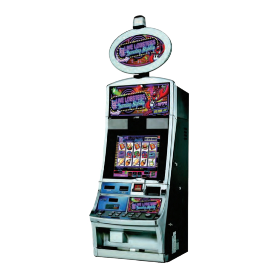
WMS Bluebird Series Service Manual & User Manual (116 pages)
Upright (BBU) Video Gaming Devices
Brand:
WMS
| Category:
Arcade Game Machines
| Size: 6.41 MB
Table of Contents
Table of Contents
3
About this Guide
13
Safety Symbols and Information
14
Preventing Injury and Damage
15
Disconnect Power Cord from Game (When Not Handling ESD-Sensitive Equipment)
15
ESD Wrist Strap
15
Figure 1-1 ESD Wrist Strap on Arm
15
Figure 1-2 Power Supply Cord Plugged into Power Entry Assembly
15
Power Game or Top Box off at the Power Switch
15
Prevent Shock and ESD
15
Special Instructions for Pcbs
15
About this Guide General Information
13
Documentation Copyright
13
Game Copyright, Trademark, and Patent Laws
13
Check Local Laws
13
CE Marking
13
Customer Product Support Center
13
Conventions
13
Text Conventions
13
CHAPTER 1: Introduction and Features
18
Reference Documentation
18
Introduction
18
Table 1-1 Reference Documentation
18
Base Game Dimensions and Weights
19
Weight
19
Table 1-2 Game Weight
19
Figure 1-1 Dimensions of BBU with 7'' Top Box (Left), 12'' Top Box (Center)
19
Power Dissipation
20
Features: Doors
20
Figure 1-2 Open BBU Doors
20
Table 1-3 Heat/Electricity Dissipation
20
Figure 1-3 Latches to Separate Doors (Left) and Lower Door Separated (Right)
21
Figure 1-4 Gas Strut
21
Figure 1-5 Components in Main Door
21
Main Door and Lower Door
21
Door Switches
22
CPU Enclosure
22
Figure 1-6 Main Door Switch above LCD Shelf
22
Figure 1-7 Belly Door Switch in Center of Inside of Belly Door
22
Figure 1-8 CPU Enclosure Installed (Left) and Four Mounting Tabs (Right)
22
Hard Meters
23
Bose® Audio System
23
Figure 1-9 the Hard Meters Inside BBU (Left) Is Visible through the LCD Bezel (Right)
23
Figure 1-10 Installed Bose Wave Guide Sound System Components
23
Top Box Connector Plate
24
Player Tracking SMIB Mounting Plate
24
Table 1-4 Cabinet Top Box Connector Plate Designations
24
Figure 1-11 Top Box Connector Plate
24
Figure 1-12 WMS SMIB Mounting Plate in Top Box
24
Top Box Mounting Hardware
25
In-Game Progressive Meter
25
Figure 1-13 Video Top Box Mounting Hardware
25
CPU Enclosures (Rohs CPU-NXT and CPU-NXT2)
26
Rohs CPU-NXT: Board Identification
26
Table 1-5 Layout of Rohs CPU-NXT
26
Figure 1-15 Layout of Rohs CPU-NXT PCB
26
Rohs CPU-NXT: Compactflash Slots and Cable Connectors
27
Figure 1-16 Compactflash Slots and Cable Connectors
27
Table 1-6 Layout of CPU-NXT2
28
Figure 1-17 Layout of CPU-NXT2 PCB
28
Blind Mate Connectors for Bulkhead Board
29
Figure 1-18 Compactflash Slots and Cable Connectors
29
Figure 1-19 Blind Mate Connectors on Outside of CPU Enclosure
29
Logic Door
30
Security Wire Holes
30
Figure 1-20 Open Logic Door (Left) and Warning Label on Logic Door (Right)
30
Figure 1-21 Security Wire Holes
30
Ethernet/Usb Port Cover Plate (in Select Jurisdictions)
31
Table 1-7 Ethernet/Usb Port Cover Plates
31
Bulkhead Board
32
Table 1-8 Bulkhead Board Connectors
32
Figure 1-22 Bulkhead Board
32
Figure 1-23 Bulkhead Board Inside Game
32
Safety Features
33
Liquid Diversion
33
Figure 1-24 Plastic Shield for AC Components, Located Behind the Power Switch (Left) and
33
Foam above Speakers
33
Plastic Shield for Power Components
33
Below Bulkhead (Right)
33
Figure 1-25 Two Foam Strips above the Speakers
33
Ground Braids
34
Electrical Requirements
34
Properly Ground Gaming Devices
34
Use Functional Power Supply Cord
34
Outdoor Use
34
Game Maintenance
34
Table 1-9 Game Power Requirements
34
Figure 1-26 Ground Braids from Door Locking Bar
34
Radio Interference
35
Replacement Fuse
35
Table 1-10 Fuse Type
35
Figure 1-27 Power Entry Assembly
35
Service Receptacle
36
Power Strip/Service Receptacle
36
Line Voltage Auto-Detect
36
Table 1-11 Service Receptacle Information
36
Figure 1-28 Power Strip Detail
36
Figure 1-29 Warning Label
36
Introduction
37
Preparation
38
ESD Prevention
38
Install Game Onto Stand
38
Figure 2-1 Bluebird Drill Fixture
38
Lock Specifications
39
Table 2-1 Lock Specifications (Inches)
39
CHAPTER 2: Installation
40
Table 2-2 Lock Specifications (Metric)
40
Figure 2-2 Shipping Lock on the Inside of the CPU Enclosure Door
40
Cashbox Locks
41
Remove Cover Plate to Install Second Lock (if Necessary)
41
Power Setup
41
Figure 2-3 Shipping Lock on the Inside of the CPU Enclosure Door
41
Figure 2-4 Power Components
41
Verify LCD Connection
42
Bulkhead Board Jumper Settings
42
Bill Acceptor Jumpers
42
Progressive Port Jumpers
42
Figure 2-5 LCD Connection to CPU Enclosure
42
Figure 2-6 Bulkhead Board Jumper Locations
42
Figure 2-7 Bill Acceptor Jumpers
43
Table 2-3 Bill Acceptor Jumpers
43
Figure 2-10 Jumper Setting at JP6 on Bulkhead Board
44
Figure 2-9 Jumper Setting at JP4 on Bulkhead Board
44
Table 2-4 Progressive Port Jumpers
44
Host 1 Jumpers
45
Host 2 Jumpers
45
Table 2-5 Host 1 Jumpers
45
Table 2-6 Host 2 Jumpers
45
Installing the Top Box
46
Mount Top Box
46
Figure 2-12 Location of Top Box Mounting Studs or Posts
46
Figure 2-13 Two Mounting Configurations for BBU Top Box
46
Install Two Crown Pieces
47
Table 2-7 Part Descriptions for Crown Pieces
47
Figure 2-14 One of Two Crown Brackets
47
Figure 2-15 Mounting Setup for Left Crown Piece (Left) and the Outside View of Properly Mounted
47
Figure 2-16 Secured Crown Piece
47
Electronic Connections
48
Table 2-8 BBU Cabinet Top Box Connector Plate Designations
48
Figure 2-17 Top Box Connector Plate
48
CHAPTER 3: Maintenance
49
CHAPTER 3: Maintenance
50
Overview
50
ESD Prevention
50
Cleaning the Game
50
Game Cabinet
50
Lcd
50
Bill Acceptor
50
Table 3-1 Division of Maintenance Responsibilities
50
Removing the Bill Acceptor and Cashbox
51
Remove the Bill Acceptor
51
Remove the Cashbox
51
Figure 3-1 Open Bill Acceptor Door
51
Figure 3-2 Open Bill Acceptor Door
51
Figure 3-3 Gripping the Lamp
52
Figure 3-4 Pulling the Lamp from the Socket
52
Button Panel Maintenance
53
Table 3-2 Bulb Size
53
Figure 3-5 Inserting the LED into the Small Button (Left) and Large Button (Right)
53
Figure 3-6 Polarity Stripe on LED (Left) and Positive Marking on Rear of Button (Right)
53
Figure 3-7 Replacing the Button Insert
54
Figure 3-8 Snapping the Lens into the Button
54
Figure 3-9 Original Button Panel and Cables
54
Remove Button Panel
54
Replacing the Button Panel Lenses and Inserts
54
Figure 3-10 Rotate the Belly Light Bracket Backward
55
Figure 3-11 Slide out the Existing Button Panel
55
Figure 3-12 Empty Button Panel Area
55
Figure 3-13 Install the Button Panel
56
Figure 3-14 Connect Cables
56
Figure 3-15 Secured Universal Animator Bracket
57
Figure 3-16 Universal Animator Without Formex Cover (Left) and with Formex Cover (Right)
57
Figure 3-17 Universal Animator Seated on Bracket
57
Mount the Universal Animator to Bracket
57
Replace SPN Components
57
Install Button Panel
56
Install the SPN Distribution Board
58
Mount SPN Board to SPN Bracket
58
Figure 3-18 SPN Bracket and SPN Distribution Board
58
Figure 3-19 Remove Top Ground Braid
58
Connect the SPN Distribution Board
58
Figure 3-20 Mount the SPN Distribution Board and Bracket
59
Figure 3-21 Replace Ground Braid
59
Connect the SPN Distribution Board
60
Connect the Universal Animator
60
Connect the Universal Animator (with SPN Distribution Board)
60
Figure 3-22 Connect the DC Power and Two SPN Cables
60
Figure 3-23 Universal Animator Connections
60
Connect the Universal Animator (Without SPN Distribution Board)
61
Figure 3-24 Connect the Ribbon Cable to the Universal Animator
61
Bose Audio System Maintenance
62
Figure 3-25 Setup Menu
62
Figure 3-26 Sound Controls
62
CHAPTER 4: Troubleshooting
63
CHAPTER 4: Troubleshooting
64
Overview
64
Tower Light Codes
64
Table 4-1 Tower Light Troubleshooting
64
Basic Game Troubleshooting
65
Table 4-2 Basic Game Troubleshooting
65
Diagnostic Tools
67
Cash Devices Diagnostics
67
Figure 4-1 Diagnostics Menu
67
Bill Acceptor Test
67
Coin Acceptor Diagnostics
67
Bill Acceptor Test
68
Figure 4-2 Cash Device Diagnostics Menu
68
Figure 4-3 JCM Billval Diagnostic Screen
68
Figure 4-4 JCM Billval Diagnostic Screen: $20 Bill Example
69
Figure 4-5 JCM Billval Diagnostic Screen: Ticket
69
Figure 4-6 JCM Billval Diagnostic Screen
70
Figure 4-7 Exit Banner
70
Figure 4-8 Coin Acceptor Diagnostics Screen
71
Hopper Diagnostics
72
Figure 4-9 Hopper Diagnostics Screen
72
Printer Diagnostics
73
Figure 4-10 Printer Diagnostics Screen
73
Figure 4-11 Printer Diagnostics Screen
73
Figure 4-12 WMSP Diagnostics Menu
74
Figure 4-13 WMSP Traffic Statistics Screen
74
Progressive Diagnostics
75
Figure 4-14 WMSP Link Statistics Screen
75
Figure 4-15 SPN Diagnostics Menu
76
Figure 4-16 SPN Traffic Statistics Screen
76
SPN Diagnostics
76
SPN Diagnostics
77
SPN Diagnostics - Link Statistics
77
SPN Devices Diagnostics
77
Figure 4-17 SPN Link Statistics Screen
77
Figure 4-18 SPN Device Diagnostics Screen
77
SPN Diagnostics - Traffic
77
Using SVC/GAT
78
Table 4-3 SPN Device Diagnostic Tests
78
Figure 4-19 Active SPN Device Diagnostic Example
78
Figure 4-20 Bluebird (Upright) CPU Enclosure
78
Figure 4-21 SVC/GAT on the Administration Menu
79
Figure 4-22 SVC Authentication Interface Screen
79
Figure 4-23 os Authentication Level 2 Screen
80
Figure 4-24 os Authentication Level 2 Screen Example
80
Tilt Codes
81
Table 4-4 Tilt Codes
81
CHAPTER 4 Figure
84
Figure
86
CHAPTER 5: Exploded Views
89
Chapter 5: Chapter
105
CHAPTER 6: BBU Video Replacement Parts
105
CHAPTER 6: BBU Video Replacement Parts
106
Overview
106
Ordering Parts
106
Electrical Parts
107
Batteries
107
Bulbs and Ballasts
107
Button Panel, Buttons, and Button Inserts
107
Table 6-1 Bulbs and Ballasts
107
Table 6-2 Batteries
107
Table 6-3 Buttons and Button Lenses
107
Cables
109
Table 6-4 Cables
109
Electrical Assemblies/ Printed Circuit Boards
110
Fuses
110
Mechanical Assemblies
110
Table 6-5 Electrical Assemblies/Printed Circuit Boards (Pcbs)
110
Table 6-6 Fuses
110
Table 6-7 Mechanical Assemblies
110
Media
111
Miscellaneous Electrical Parts
111
RAM 256MB to 512MB Upgrade Kit
111
Switches
111
Table 6-10 Switches
111
Table 6-11 Miscellaneous Electrical Parts
111
Table 6-8 Media
111
Table 6-9 RAM 256MB to 512MB Upgrade Kit
111
Mechanical Parts
112
Cams
112
Marquees
112
Marquee Adaptor Kits
112
Miscellaneous Mechanical Parts
112
Plates, Brackets, and Covers
112
Table 6-12 Cams
112
Table 6-13 Marquees
112
Table 6-14 Marquee Adaptor Kits
112
Table 6-15 Miscellaneous Mechanical Parts
112
Top Box Glass Mounting Frame
113
Table 7 Part Descriptions
113
Table 6-1 Top Box Glass Mountaining Frame
113
Transmissive Reels
113
Top Box Kits
114
Tower Lights
114
Peripherals
114
Table 6-2 Top Box Kits
114
Table 6-3 Tower Lights
114
Other Parts
115
Decals & Inserts
115
Labels
115
Top Award Inserts
115
Table 6-4 Insert Bill here Decal
115
Table 6-5 Labels
115
Table 6-6 Top Award Inserts
115
Top Coin Entry Inserts
116
Tower Light Inserts
116
Table 6-7 Top Coin Entry Inserts
116
Table 6-8 Tower Light Inserts
116
Advertisement
Advertisement
Related Products
WMS Categories
Adapter
Motherboard
Microphone system
Arcade Game Machines
More WMS Manuals
Login
Sign In
OR
Sign in with Facebook
Sign in with Google
Upload manual
Upload from disk
Upload from URL