
Subscribe to Our Youtube Channel
Summary of Contents for WMS Bluebird Series
- Page 1 Service Manual & User Guide Upright (BBU) Video Gaming Devices 24/7 Product Support Center: 1.866.967.4457 or CustomerSupport@WMS.com WMS Gaming, Inc. • 800 S. Northport Boulevard • Waukegan, IL 60085...
-
Page 3: Table Of Contents
Table of Contents ABOUT THIS GUIDE: General Information Documentation Copyright................1-1 Game Copyright, Trademark, and Patent Laws........1-1 Check Local Laws..................1-1 CE Marking ....................1-1 Customer Product Support Center............1-1 Conventions....................1-1 Text Conventions ................1-1 Safety Symbols and Information ............1-2 Preventing Injury and Damage..............1-3 Prevent Shock and ESD ..............1-3 Power Game or Top Box OFF at the Power Switch ...... - Page 4 Table of Contents: Ground Braids ................1-18 Electrical Requirements ................1-18 Properly Ground Gaming Devices ..........1-18 Use Functional Power Supply Cord..........1-18 Outdoor Use ................... 1-18 Game Maintenance ................ 1-18 Radio Interference ................1-19 Replacement Fuse ................. 1-19 Service Receptacle................. 1-20 Power Strip/Service Receptacle .............
- Page 5 Connect the Universal Animator .............3-12 Connect the Universal Animator (with SPN Distribution Board)..3-12 Connect the Universal Animator (without SPN Distribution Board)..3-13 Bose Audio System Maintenance ............3-14 ® CHAPTER 4: Troubleshooting Table of Contents ..................4-1 Overview ....................4-2 Tower Light Codes..................4-2 Basic Game Troubleshooting ............4-3 Diagnostic Tools ..................4-5 Cash Devices Diagnostics ..............4-5...
- Page 6 Table of Contents: Other Parts .....................6-11 Decals & Inserts................6-11 Labels ..................... 6-11 Top Award Inserts ................6-11 Top Coin Entry Inserts ..............6-12 Tower Light Inserts................6-12 November 2007...
- Page 7 List of Tables CHAPTER 1: Introduction and Features Table 1-1 Reference Documentation..............1-2 Table 1-2 Game weight..................1-3 Table 1-3 Heat/Electricity Dissipation..............1-4 Table 1-4 Cabinet Top Box Connector Plate Designations........1-8 Table 1-5 Layout of RoHS CPU-NXT..............1-10 Table 1-6 Layout of CPU-NXT2................1-12 Table 1-7 Ethernet/USB Port Cover Plates.
- Page 8 List of Tables: Table 6-15 Miscellaneous Mechanical Parts ............6-8 Table 6-16 Plates, Brackets and Covers ...............6-8 Table 7 Part Descriptions ..................6-9 Table 6-1 Top Box Glass Mountaining Frame ............6-9 Table 6-2 Top Box Kits ..................6-10 Table 6-3 Tower Lights ..................6-10 Table 6-4 Insert Bill Here Decal ................6-11 Table 6-5 Labels ....................6-11 Table 6-6 Top Award Inserts ................6-11...
- Page 9 Installed Bose Wave Guide Sound System components..........1-7 Figure 1-11 Top Box Connector Plate................... 1-8 Figure 1-12 WMS SMIB Mounting Plate in Top Box..............1-8 Figure 1-13 Video Top Box mounting hardware................1-9 Figure 1-14 In-Game Progressive Meter location................. 1-9 Figure 1-15 Layout of RoHS CPU-NXT PCB.
- Page 10 List of Figures: Figure 2-10 Jumper setting at JP6 on Bulkhead Board..............2-8 Figure 2-11 Host 1 (bottom) and Host 2 (top) jumpers, both set to RS-232.........2-9 Figure 2-12 Location of Top Box Mounting Studs or Posts............2-10 Figure 2-13 Two mounting configurations for BBU Top Box.
- Page 11 Figure 4-14 WMSP Link Statistics screen................... 4-13 Figure 4-15 SPN Diagnostics menu.................... 4-14 Figure 4-16 SPN Traffic Statistics screen..................4-14 Figure 4-17 SPN Link Statistics screen..................4-15 Figure 4-18 SPN Device Diagnostics screen................4-15 Figure 4-19 Active SPN device diagnostic example.
- Page 12 List of Figures: November 2007...
-
Page 13: About This Guide General Information
WMS. WMS reserves the right to revise this documentation and to make changes in content from time to time without obligation on the part of WMS to provide notification of such revision or change. -
Page 14: Safety Symbols And Information
About this Guide: General Information Safety Symbols and When required, information is provided in procedures about potential challenges and dangers. The Information terms WARNING, CAUTION, and NOTE are used for specific safety reasons. For emphasis, WARNING and CAUTION appear beside the characteristic triangle symbol. Table 1 lists notice icons used in this guide. -
Page 15: Preventing Injury And Damage
Preventing Injury and Damage Preventing This section provides instructions for preventing electrical injury and protecting components from Injury and ESD damage. Damage Depending on the procedure, one or more of the measures listed below must be taken to prevent Prevent Shock and electrical shock and/or electrostatic discharge (ESD) when servicing the game. - Page 16 About this Guide: General Information October 2007...
- Page 17 Chapter 1 Introduction and Features Table of Reference Documentation ............1-2 Contents Introduction.................. 1-2 Base Game Dimensions and Weights........1-3 Weight....................1-3 Power Dissipation ................1-4 Features: Doors ................1-4 Main Door and Lower Door...............1-5 Door Switches...................1-6 CPU Enclosure................1-6 Hard Meters .................. 1-7 Bose®...
-
Page 18: Chapter 1: Introduction And Features
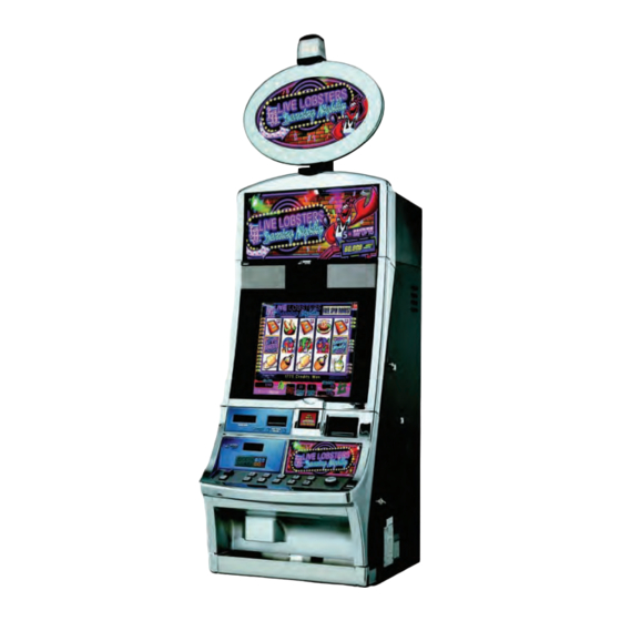
Introduction The Bluebird Upright cabinet (BBU) from WMS is designed from an end-user point-of-view. Listening to their customers and technicians, engineers designed Bluebird with a lower button panel and a modified coin tray to provide both comfort and security. The sound system features two mid- range speakers for an encompassing audio effect. -
Page 19: Base Game Dimensions And Weights
Skid 25 lbs (11 kg) CAUTION: The maximum weight of a game is 452 lbs. (205 kg). Verify that any non-WMS game stand specifications meet this weight requirement before mounting the game. Using inadequate game stands voids the WMS Warranty and may lead to distortion of the game cabinet, including the inability to close and lock the Main Door. -
Page 20: Power Dissipation
Chapter 1: Introduction and Features Power Dissipation Table 1-3 lists the power dissipation and BTU ratings for the BBU-Video and BBU-Video Dual Screen. Current values for all machines are based on a 120VAC configuration, with Bill Acceptors installed. The British Thermal Units (BTUs) were calculated by using the following equation: BTUs = 3.413 * voltage * current Any decrease in BTUs due to actual work performed (spinning Hopper motor) was neglected. -
Page 21: Main Door And Lower Door
Features: Doors Main Door and The Bluebird Main Door is a two-part design comprised of the following: Lower Door An individual lower door, Figure 1-3, which opens with the lower latch, Figure 1-3 The full Main Door, which opens with the upper latch, Figure 1-3 Figure 1-3 Latches to separate doors (left) and Lower Door separated (right). -
Page 22: Door Switches
Chapter 1: Introduction and Features Door Switches The Main Door switch confirms that the door is closed properly and places the game into play mode. The switch is located on the right side of the cabinet, above the shelf, Figure 1-6. -
Page 23: Hard Meters
Hard Meters Hard Meters The hard meters, Figure 1-9, are located behind the Main Door on the right side of the game, and track the following information: (A) Coins In (B) Coins Out (C) Coins Drop (D) Bills In (E) Jackpots (F) Blank Figure 1-9 The Hard Meters inside BBU (left) is visible through the LCD Bezel (right). -
Page 24: Top Box Connector Plate
1-12. The SMIB Mounting Plate may be removed. Plate Figure 1-12 WMS SMIB Mounting Plate in Top Box. 1 Disengage the pull pin securing the WMS SMIB Mounting Plate to the Top Box, Figure 1-12 (A). 2 Lift and pull the pull pin towards you to disengage the mounting tabs, Figure 1-12 (B). -
Page 25: Top Box Mounting Hardware
Top Box Mounting Hardware Top Box The mounting hardware includes mounting posts that engage the Mounting Keyholes on the Top Mounting Box, Figure 1-13 (A). Hardware Figure 1-13 Video Top Box mounting hardware. In-Game If applicable, the Progressive Meter, Figure 1-14 (A), mounts into the game Top Box. -
Page 26: Cpu Enclosures (Rohs Cpu-Nxt And Cpu-Nxt2)
1-10 Chapter 1: Introduction and Features CPU Enclosures This section contains information about the RoHS CPU-NXT and CPU-NXT2. (RoHs CPU-NXT and CPU-NXT2) RoHs CPU-NXT: All components are on the top side of the Printed Circuit Board (PCB). Reference Figure 1-17 Board Identification Table 1-6 to identify the components on the PCB. -
Page 27: Rohs Cpu-Nxt: Compactflash Slots And Cable Connectors
1-11 CPU Enclosures (RoHs CPU-NXT and CPU-NXT2) The RoHS CPU-NXT has two CompactFlash slots and five cable connectors on the outside of the CPU RoHS CPU-NXT: Enclosure: CompactFlash Slots and Cable CompactFlash slot for OS software, Figure 1-18 Connectors CompactFlash slot for game software, Figure 1-18 Auxiliary Serial Connector, Figure 1-18... -
Page 28: Table 1-6 Layout Of Cpu-Nxt2
1-12 Chapter 1: Introduction and Features CPU-NXT2 Board On CPU-NXT2, all components are on the top side of the Printed Circuit Board (PCB). Reference Identification Figure 1-17 Table 1-6 to identify the components on the PCB. CAUTION: Do not remove the PCB from the enclosure. Figure 1-17 Layout of CPU-NXT2 PCB. -
Page 29: Blind Mate Connectors For Bulkhead Board
1-13 CPU Enclosures (RoHs CPU-NXT and CPU-NXT2) CPU-NXT2: The CPU-NXT2 has two CompactFlash slots and ten cable connectors on the outside of the CompactFlash Slots Enclosure: and Cable CompactFlash slot for OS software, Figure 1-18 Connectors CompactFlash slot for game software, Figure 1-18 SPDIF, Figure 1-18... -
Page 30: Logic Door
1-14 Chapter 1: Introduction and Features Logic Door The Logic Door, Figure 1-20 (A), covers the PCB and two slots for the CompactFlash cards. NOTE: CPU-NXT2 cannot be installed or removed without unlocking and/or removing the Logic Door, as indicated on the yellow warning label on the Logic Door, Figure 1-20 (B). -
Page 31: Ethernet/Usb Port Cover Plate (In Select Jurisdictions)
1-15 Ethernet/USB Port Cover Plate (in select jurisdictions) Ethernet/USB In select jurisdictions, a metal cover plate protects the Ethernet/USB ports on CPU-NXT and Port Cover Plate CPU-NXT2 enclosures. Table 1-7 lists the CPU Enclosures and corresponding cover plates. (in select Table 1-7 Ethernet/USB Port Cover Plates. -
Page 32: Bulkhead Board
1-16 Chapter 1: Introduction and Features Bulkhead Board Most game components, including peripherals, connect to the Bulkhead Board, Figure 1-22 Table 1-8 NOTE: The current revision of the Bulkhead Board is compliant with the Restriction on use of Certain Hazardous Substances in Electrical and Electronic Equipment (RoHS; Directive 2002/ 96/EC) regulations. -
Page 33: Safety Features
1-17 Safety Features Safety Features Several safety features are included in the Bluebird Upright cabinet. Liquid Diversion The liquid diversion parts on the game are designed to handle less than one liter of liquid. During game setup, verify that all parts are securely installed and adequately cover the sensitive components. -
Page 34: Ground Braids
Avoid electrical shocks by using proper grounding at all times. Do not plug in the gaming device until Gaming Devices you inspect and verify the outlet. Only connect the WMS device to grounded, three-wire outlets. Do not use a cheater plug to defeat the power cord’s ground pin. Do not cut off the ground pin. After servicing a gaming device, ensure that ground wires are secure. -
Page 35: Radio Interference
1-19 Electrical Requirements Radio Interference Please be aware of the safety notices listed below. Pending approval, some or all of the following may apply: FCC Interference Notice. This equipment has been tested and complies with the limits for a Class B digital device, pursuant to Part 15 of the FCC Rules. These limits provide reasonable protection against harmful interference when the equipment is operated in a commercial environment. -
Page 36: Service Receptacle
Hertz 120 VAC 50/60Hz 220-240 VAC 50-60Hz Line Voltage The main power supply used in WMS Bluebird products has a line voltage feature that automatically Auto-Detect detects the proper line voltage needed for the game and adjusts accordingly. November 2007... -
Page 37: Introduction
Chapter 2 Installation Table of Introduction.................. 2-1 Contents Preparation ................... 2-2 ESD Prevention ................2-2 Install Game onto Stand..............2-2 Lock Specifications ................2-3 Change CPU Shipping Lock(s) ............2-4 Cashbox Locks .................2-5 Power Setup ................. 2-5 Verify LCD Connection..............2-6 Bulkhead Board Jumper Settings ..........2-6 Bill Acceptor Jumpers ...............2-7 Progressive Port Jumpers..............2-8 Installing the Top Box.............. -
Page 38: Preparation
Figure 2-1. To obtain the fixture, contact WMS Field Service. CAUTION: The maximum weight for any BBU game is 452 lbs (205 kg). Verify that any non-WMS game stand specifications meet this weight requirement before mounting the game. Using inadequate game stands voids the WMS Warranty and may lead to distortion of the game cabinet, including the inability to close and lock the Main Door. -
Page 39: Lock Specifications
Large shaded holes are 2.75" diameter Small shaded holes are 0.50" diameter CAUTION: WMS requires that all BBU games are mounted to Game Stands using four bolts for stability and security. Failing to do so may lead to cabinet warping. -
Page 40: Chapter 2: Installation
Chapter 2: Installation Table 2-2 Lock Specifications (metric) Rotation to Designed Extended Lock (viewed Lock Location Length Length* Description Cam Part No. from key end) Upper (Main) 16 mm 13 mm inside 38 mm lg. 6 mm 01-001614-04 clockwise Door or outside offset Lower (Belly) -
Page 41: Remove Cover Plate To Install Second Lock (If Necessary)
Power Setup Remove Cover Plate To Install Second Lock (If necessary) If a second lock is required in the place of the cover plate, Figure 2-3 (A), complete the following steps to remove the cover plate: 1 Use a screwdriver to punch the perforated cover plate out of the CPU Enclosure Door, Figure 2-3 (A). -
Page 42: Verify Lcd Connection
Chapter 2: Installation Verify LCD If a Belly LCD is installed, verify the VGA cable is connected to the CPU Board, Figure 2-5. Connection Figure 2-5 LCD connection to CPU Enclosure. Bulkhead Board The Bulkhead Board includes ten jumpers, Figure 2-6, that determine the game communication Jumper interface with the Bill Acceptor, Progressive System, and the Host System(s). -
Page 43: Table 2-3 Bill Acceptor Jumpers
Bulkhead Board Jumper Settings Bill Acceptor Three jumpers on the Bulkhead Board control the Bill Acceptor interface option used by the game, Jumpers Figure 2-7. Three interface options are available, including RS-232, TTL, and Current Loop. Figure 2-7 Bill Acceptor Jumpers. Figure 2-8 Diagram of Bill Acceptor Jumpers. -
Page 44: Table 2-4 Progressive Port Jumpers
Chapter 2: Installation Progressive Port Three jumpers on the Bulkhead Board control the type of progressive system and interface used by Jumpers the game. If applicable, confirm that the Progressive Jumpers (PROG JMPRS) at JP4, JP5, and JP6, are set to work with a Progressive System: The Jumper at JP4 must be set to RS485, Figure 2-9. -
Page 45: Host 1 Jumpers
Bulkhead Board Jumper Settings Host 1 Jumpers Bluebird may be configured as a dual host system. Two jumpers control the Host 1 communication interface, Figure 2-11. The two options are RS-232 and RS-485, Table 2-5. Figure 2-11 Host 1 (bottom) and Host 2 (top) jumpers, both set to RS-232. Table 2-5 Host 1 jumpers. -
Page 46: Installing The Top Box
2-10 Chapter 2: Installation This section describes the steps to secure and connect the Top Box to a BBU. Installing the Top Box ESD: Ensure that you take the following measures to prevent ESD: Turn the game OFF at the Power Switch. Remove the AC Line Cord from the Power Entry Assembly. -
Page 47: Install Two Crown Pieces
2-11 Installing the Top Box Two Crown Pieces, located in the final packet assembly of certain Top Boxes, are mounted to the front Install Two Crown of the Top Box Frame. Each Crown Piece is made up of two components: the outside rail and the inside Pieces bracket, 2-7. -
Page 48: Electronic Connections
2-12 Chapter 2: Installation Electronic Complete the following electronic connections to the Top Box Connector Plate, Figure 2-17 Connections Table 2-8 1 Gather all of the cables from the Top Box and confirm that there is access to the Top Box Connector Plate, which is in the left section of the Top Box, Figure 2-17. -
Page 49: Chapter 3: Maintenance
Chapter 3 Maintenance Table of Overview..................3-2 Contents ESD Prevention................3-2 Cleaning the Game ..............3-2 Game Cabinet...................3-2 LCD....................3-2 Bill Acceptor ..................3-2 Removing the Bill Acceptor and Cashbox ........ 3-3 Remove the Bill Acceptor..............3-3 Remove the Cashbox ...............3-3 Button Panel Maintenance............3-4 Inserting the LED ................3-4 Replacing the Button Panel Lenses and Inserts .......3-6 Remove Button Panel ...............3-6... -
Page 50: Chapter 3: Maintenance
Chapter 3: Maintenance Overview WMS games function optimally with periodic maintenance. The tasks in this section are performed by personnel that fit into three categories: Drop Crew Attendants Technicians Table 3-1 identifies the tasks performed by these personnel: Table 3-1 Division of maintenance responsibilities... -
Page 51: Removing The Bill Acceptor And Cashbox
Removing the Bill Acceptor and Cashbox Removing the The procedures in this section describe how to remove the Bill Acceptor and Cashbox from the Bill Acceptor BBU. and Cashbox Remove the Bill Complete the following steps to remove the Bill Acceptor from the game: Acceptor 1 Unlock and open the Belly Door. -
Page 52: Figure 3-3 Gripping The Lamp
Chapter 3: Maintenance Button Panel This section contains maintenance procedures for the Button Panel. Maintenance Inserting the LED To remove the button lamp and insert the LED, complete the following steps: 1 Using the needle-nose pliers, gently grip the lamp within the button, Figure 3-3 (A). -
Page 53: Button Panel Maintenance
Button Panel Maintenance 3 Using the needle-nose pliers, insert the LED into the button socket by determining the following Table 3-2: Table 3-2 Bulb size. If the button is a... then... small square unit use LED 24-018185-00-00 large circular unit use LED 24-018186-00-00 Figure 3-5 Inserting the LED into the small button (left) and large button (right). -
Page 54: Replacing The Button Panel Lenses And Inserts
Chapter 3: Maintenance Replacing the Replace the lens and button insert by completing the following steps: Button Panel 1 Replace the saved insert onto the button, Figure 3-7. Lenses and Inserts Figure 3-7 Replacing the button insert. 2 Snap the lens back onto the button by using the forefinger pushing straight down at the center, Figure 3-8. -
Page 55: Figure 3-10 Rotate The Belly Light Bracket Backward
Button Panel Maintenance 5 Disconnect Belly Light cable from the Belly Light cable connector, Figure 3-9. 6 Using a 1/4" nut driver, remove the two #6 hex screws securing the Belly Light Bracket, Figure 3-9. 7 Using an 11/32" nut driver, remove the two #8 Keps nuts securing the Belly Light Bracket, Figure 3-9. -
Page 56: Install Button Panel
Chapter 3: Maintenance Install Button Panel Use the following instructions to install the Button Panel: 1 From the inside of the Door, slide the Button Panel into the bracket, Figure 3-13. Figure 3-13 Install the Button Panel. 2 Route the Button Panel cables through the cable clamp, Figure 3-14. -
Page 57: Mount The Universal Animator To Bracket
Button Panel Maintenance Replace SPN This section provides the procedure for replacing Smart Peripheral Network (SPN) components Components required for select SPN-controlled Button Panels. Mount the Universal Animator to Bracket Complete the following steps to mount the Universal Animator to the SPN Bracket. ESD: Before handling the SPN Distribution Board, or any PCB, confirm ESD precautions are followed. -
Page 58: Install The Spn Distribution Board
3-10 Chapter 3: Maintenance Install the SPN Complete the procedures below to mount and connect the SPN Distribution Board (A-012604-02- Distribution 00). Board Mount SPN Board to Complete the following steps to mount the SPN Board to the SPN Bracket. SPN Bracket ESD: Before handling the SPN Distribution Board, or any PCB, confirm ESD precautions are followed. -
Page 59: Figure 3-20 Mount The Spn Distribution Board And Bracket
3-11 Install the SPN Distribution Board 5 Align the two mounting holes on the SPN Bracket, Figure 3-18 (B), with the top two 8-32 mounting studs on the left wall of the cabinet, Figure 3-20 (A). Figure 3-20 Mount the SPN Distribution Board and Bracket. 6 Replace the ground braid over the top 8-32 mounting stud and the SPN Distribution Board, Figure 3-21 (A). -
Page 60: Connect The Spn Distribution Board
3-12 Chapter 3: Maintenance Connect the SPN Complete the following steps to connect the SPN Distribution Board: Distribution Board 1 Connect either end of the 8-pin DC Power Cable (H-013768-04) to either of the 8-pin connectors on the SPN Distribution Board, Figure 3-22 (A). -
Page 61: Connect The Universal Animator (Without Spn Distribution Board)
3-13 Install the SPN Distribution Board Connect the Universal Animator (without SPN Distribution Board) Complete the following steps to connect the Universal Animator when no SPN Distribution Board is present: 1 Connect the 8-inch Ribbon Cable to the Universal Animator, Figure 3-24 (A). -
Page 62: Bose Audio System Maintenance
3-14 Chapter 3: Maintenance ® Bose Audio The Bose Sound System features superb sound quality and clear directionality. Complete the System following steps to adjust the volume: Maintenance ® NOTE: The Bose Sound System contains no serviceable parts and must be replaced as a unit. Do not remove speaker screens. -
Page 63: Chapter 4: Troubleshooting
Chapter 4 Troubleshooting Table of Overview..................4-2 Contents Tower Light Codes............... 4-2 Basic Game Troubleshooting ............. 4-3 Diagnostic Tools ................4-5 Cash Devices Diagnostics ..............4-5 Bill Acceptor Test ................4-6 Coin Acceptor Diagnostics..............4-9 Hopper Diagnostics.................4-10 Printer Diagnostics................4-11 Progressive Diagnostics............4-12 WMSP Diagnostics - Traffic Statistics ..........4-12 WMSP Diagnostics - Link Statistics ..........4-13 SPN Diagnostics ................ -
Page 64: Chapter 4: Troubleshooting
Chapter 4: Troubleshooting Overview The purpose of this chapter is to guide the troubleshooting steps and considerations for the BBU Video game. In addition to several basic conditions, this chapter explains the functionality of diagnostic tools that thoroughly ensure game functionality, as well as tools for identifying operational errors in the game. -
Page 65: Basic Game Troubleshooting
Basic Game Troubleshooting Basic Game Reference Table 4-2 for a list of basic BBU troubleshooting steps. Troubleshooting Table 4-2 Basic Game Troubleshooting. Game Condition Troubleshooting Steps The game is plugged in and the LCD is 1 Check the power cord from the Power Entry Assembly to the power blacked out. - Page 66 Chapter 4: Troubleshooting Table 4-2 Basic Game Troubleshooting. (continued) Game Condition Troubleshooting Steps Tower Light not working. 1 Check to see if Tower Light is connected to Top Box Connector Plate. 2 Check connection to Bulkhead Board. 3 Replace Tower Light Bulbs. 4 Replace CPU.
-
Page 67: Diagnostic Tools
Diagnostic Tools Diagnostic CPU-NXT™ includes diagnostic tools to test game components and verify functionality. Some of the Tools components that are tested using the Administration Menu include: Compact Flash EEPROMS Bill Acceptor Coin Acceptor Hopper Printer Reference the following sections for detailed steps on troubleshooting these components. Cash Devices The Diagnostics Menu, Figure... -
Page 68: Bill Acceptor Test
Chapter 4: Troubleshooting Bill Acceptor Test Complete the following steps to initiate a Bill Acceptor Test: 1 From the Administration Menu, select Diagnostics. 2 Select Input/Output Diagnostics. 3 Select Cash Device Diagnostics, Figure 4-2. Figure 4-2 Cash Device Diagnostics Menu. 4 Select Bill Validator. -
Page 69: Figure 4-4 Jcm Billval Diagnostic Screen: $20 Bill Example
Diagnostic Tools 6 A message regarding the inserted bill or voucher displays, Figure 4-4 Figure 4-5. Figure 4-4 JCM Billval Diagnostic screen: $20 bill example. Figure 4-5 JCM Billval Diagnostic screen: ticket. 16-020834-00... -
Page 70: Figure 4-6 Jcm Billval Diagnostic Screen
Chapter 4: Troubleshooting 7 Select Reject to return the bill or ticket. A message displays to denote the successful rejection, Figure 4-6. NOTE: After a time-out period, the Bill Acceptor rejects the bill or voucher automatically. Figure 4-6 JCM Billval Diagnostic screen. 8 Press Exit or Return to Game. -
Page 71: Figure 4-8 Coin Acceptor Diagnostics Screen
Diagnostic Tools Coin Acceptor Complete the following steps to access the Coin Acceptor Test: Diagnostics 1 From the Administration Menu, select Diagnostics. 2 Select Input/Output Diagnostics. 3 Select Cash Devices Diagnostics. 4 Select Coin Acceptor. The Coin Acceptor Diagnostic screen displays, Figure 4-8. -
Page 72: Hopper Diagnostics
4-10 Chapter 4: Troubleshooting Hopper Diagnostics Complete the following steps to test the Hopper: 1 From the Administration Menu, select Diagnostics. 2 Select Input/Output Diagnostics. 3 Select Cash Devices Diagnostics. 4 Select Hopper. The Hopper Diagnostic screen displays, Figure 4-9. Figure 4-9 Hopper Diagnostics screen. -
Page 73: Printer Diagnostics
4-11 Diagnostic Tools Printer Diagnostics Complete the following steps to test the Printer: 1 From the Administration Menu, select Diagnostics. 2 Select Input/Output Diagnostics. 3 Select Cash Devices Diagnostics. 4 Select Printer. The Printer Diagnostic screen displays, Figure 4-10. Figure 4-10 Printer Diagnostics screen. 5 Select Print Void Ticket. -
Page 74: Figure 4-12 Wmsp Diagnostics Menu
Chapter 4: Troubleshooting Progressive Reference this section for Progressive Diagnostics: Diagnostics WMSP Diagnostics - This function displays WMS Progressive traffic data corresponding to the game. Complete the following steps: Traffic Statistics 1 From the Administration Menu, select Diagnostics. 2 Select WMSP Diagnostics, Figure 4-12. -
Page 75: Progressive Diagnostics
4-13 Progressive Diagnostics WMSP Diagnostics - This function displays WMS Progressive statistical link data corresponding to the game. Complete Link Statistics the following steps: 1 From the Administration Menu, select Diagnostics. 2 Select WMSP Diagnostics, Figure 4-12. 3 Select WMSP Link Statistics, Figure 4-12. -
Page 76: Figure 4-15 Spn Diagnostics Menu
4-14 Chapter 4: Troubleshooting The Progressive System is a Smart Peripheral Network (SPN) device. Reference this section for Diagnostics SPN Diagnostics. SPN Diagnostics - This function displays SPN traffic data corresponding to the game. Complete the following steps: Traffic 1 From the Administration Menu, select Diagnostics. 2 Select SPN Diagnostics, Figure 4-15. -
Page 77: Spn Diagnostics
4-15 SPN Diagnostics SPN Diagnostics - This function displays SPN link data corresponding to the game. Complete the following steps: Link Statistics 1 From the Administration Menu, select Diagnostics. 2 Select SPN Diagnostics, Figure 4-15. 3 Select SPN Link Statistics, Figure 4-15. -
Page 78: Using Svc/Gat
4-16 Chapter 4: Troubleshooting 4 To perform an SPN device diagnostic test, select Start next to the desired device. The Device Diagnostics screen displays the device actively running its diagnostic test, Figure 4-19. Figure 4-19 Active SPN device diagnostic example. Table 4-3 for information on the individual SPN device diagnostic tests. -
Page 79: Figure 4-21 Svc/Gat On The Administration Menu
4-17 Using SVC/GAT 4 Select SVC/GAT, Figure 4-21. Figure 4-21 SVC/GAT on the Administration Menu. The SVC Authentication Interface screen displays, Figure 4-22. Figure 4-22 SVC Authentication Interface screen. 5 Select the Stage 1 or Stage 2 button to verify any of the available software components. 16-020834-00... -
Page 80: Figure 4-23 Os Authentication Level 2 Screen
4-18 Chapter 4: Troubleshooting 6 Depending on the component selected, an information screen displays, identifying the Part Number, Function, Media Type, Media Size, and Time Since Last Verified, Figure 4-23. Figure 4-23 OS Authentication Level 2 screen. 7 Follow the instructions provided on the screen to perform the authentication, Figure 4-24. -
Page 81: Tilt Codes
4-19 Tilt Codes Tilt Codes Refer to Table 4-4 for a definition and possible solution(s) for the tilts displayed by a CPU-NXT game. Table 4-4 Tilt Codes . Display Definition Possible Solution(s) Assert Fail Message displays: When doing a RAM clear, be sure to wait for RAM clear to complete. - Page 82 4-20 Chapter 4: Troubleshooting Table 4-4 Tilt Codes (continued). Display Definition Possible Solution(s) Closure D Drop Door was closed. No action required. Error clears after one game is played. Closure H Hatch Door was closed. (Slant No action required. Error clears after one game is ONLY) played.
- Page 83 4-21 Tilt Codes Table 4-4 Tilt Codes (continued). Display Definition Possible Solution(s) EPROM System Critical error: An invalid signature Perform the corresponding solution: Error ID was detected and all processes RAM Clear were suspended. Replace the CPU Board battery and RAM Clear. Extra Coin Out The OS detected a coin out after Check Hopper and knife.
-
Page 84: Chapter 4 Figure
4-22 Chapter 4: Troubleshooting Table 4-4 Tilt Codes (continued). Display Definition Possible Solution(s) Hopper Tamper The OS detected that the coin Check Hopper coin out switch. pulse was too short or the coin pulse occurred during no payout. IGM Bad Firmware The firmware installed in the Run SPN Diagnostics and make sure that the Version... - Page 85 4-23 Tilt Codes Table 4-4 Tilt Codes (continued). Display Definition Possible Solution(s) Open Door B Belly Door is open. Check the Belly Door. Check connections on cherry switch. Replace switch. Replace the CPU Board. Replace Bulkhead. Open Door D Drop Door is open. Check the Drop Door.
-
Page 86: Figure
4-24 Chapter 4: Troubleshooting Table 4-4 Tilt Codes (continued). Display Definition Possible Solution(s) Power Fault while The Printer lost power while Check power connection to Printer. Printing printing. Power Reset The game powered up. No action required. Error clears after one game is played. - Page 87 4-25 Tilt Codes Table 4-4 Tilt Codes (continued). Display Definition Possible Solution(s) Program Error Critical error: A program detected Turn the Attendant Key to display the fault an unrecoverable error and all information. processes were suspended. Turn the Attendant Key a second time to force a restart.
- Page 88 4-26 Chapter 4: Troubleshooting Table 4-4 Tilt Codes (continued). Display Definition Possible Solution(s) Stacker Switch Bill Acceptor Stacker Door is Check the Bill Acceptor Stacker/Cashbox Door. Open open. Check connections on cherry switch. Replace switch. Replace the CPU Board. Replace Bulkhead. Touch Screen The controller reported an error Calibrate the Touch Screen.
-
Page 89: Chapter 5: Exploded Views
Chapter 5 Exploded Views Table of Contents Bluebird Upright (BBU) Video Cabinet Power Components.. 5 - 2 Bluebird Upright (BBU) Video Cabinet (page 1 of 2) ....5 - 3 Bluebird Upright (BBU) Video Cabinet (page 2 of 2) ....5 - 4 Bluebird Upright Video Cabinet (BBU) Upper Door .... - Page 90 Chapter 5: Exploded Views Bluebird Upright (BBU) Video Cabinet Power Components ITEM DESCRIPTION POWER STRIP BALLAST/POWER SWITCH ASSEMBLY BULKHEAD PANEL ASSEMBLY CPU ENCLOSURE 24V POWER SUPPLY/BOSE AMP ASSEMBLY POWER ENTRY ASSEMBLY ATX DC POWER SUPPLY...
- Page 91 Chapter 5: Exploded Views Bluebird Upright (BBU) Video Cabinet (page 1 of 2) ITEM PART NUMBER DESCRIPTION Q TY 1 A-015733 ASY: 24V PWR SPLY W/AMP-BBU 2 6555-009823-01-00 ASSY: BOSE-W/GDE-UBX 3 01-013211 BRKT: T/B CONN-BUX 4 01-018446-00-00 CVR: TB CONN PLT-BBU 5 01-018447-00-00 BRKT: TB CONN CVR STRAP-BBU 6 4008-007026-04...
- Page 92 Chapter 5: Exploded Views Bluebird Upright (BBU) Video Cabinet (page 2 of 2) ITEM PART NUMBER DESCRIPTION 29 03-008255 CHUTE: CN XFER-UBX 30 A-010533 ASY: ATX DC PWR SPLY-UBX 31 A-015309-01-00 ASY: PDU, BUX 32 01-008307-ZZZ CVR: CAB-A/MECH-UBV 33 01-010676-01-00 HSG: WBA/CAB-MTG-BUX 34 01-008248 BRKT: WBA-CONN MTG-UBV...
- Page 93 Chapter 5: Exploded Views Bluebird Upright Video Cabinet (BBU) Upper Door ITEM PART NUMBER DESCRIPTION A-010582-XX-YY-ZZZ ASSY: UPR DR CSTG-BUR 2 A-011048 BBU BARRIER PANEL ATO 3 01-013185-ZZZ BRKT: BRR PNL-CRDR MTG-BBU 4 01-013186 CLLR: BRR PNL-CRDR MTG-BBU 5 4008-007026-06 8-32x06 phl hxw f ms st zn 6 4010-007027-06 10-24x06 phl hxw f tt st zn...
- Page 94 Chapter 5: Exploded Views Bluebird Upright (BBU) Video Cabinet Lower Door BBU-LOWER DOOR NO LCD ITEM PART NUMBER DESCRIPTION A-016753-00-00-ZZZ ASY: LWR DR-BUX 2 03-008240 BZL: WBA-EXTN-UBV 3 4700-00060-00 FW: .219X0.500X.062 CRS ZN 4 4008-008342-05B 8-32X05 HEX SOC SHL ST ZN 5 01-016185-01-00 PLT: BAP PCB MTG-BUX 6 A-012562-01-00...
- Page 95 Chapter 5: Exploded Views Bluebird Upright (BBU) Door Latch Mechanism ITEM PART NUMBER DESCRIPTION 01-008214 BAR: CAB-MAIN LOC-UBV 2 4700-002560-00 FW: .320x .750x.030 CRS ZN 3 4008-000203-06 8-32x06 PHL TRS MS ST ZN 4 01-010209 BRKT: CAB-DR REL-UBX 5 4420-01141-00 NUT: 1/4 - 20 FLANGRIP ST ZN 6 02-008218...
- Page 96 Chapter 5: Exploded Views Bluebird Upright (BBU) Bill Acceptor ITEM PART NUMBER DESCRIPTION 01-013248-01-00 HSG: WBA - BUX 2 20-004576 LOCK: THUMB, NO KEY, SHIPPING 3 01-12793-08 CAM: FLT-1.25-DUAL MTG. 4 4008-007027-04 8-32x04 PHL HXW F ST TT ZN 5 01-008302 BRKT: WBA-DR SW ACTR-UBX 6 4006-01027-04 6-32x04 PHL RDW MS ST ZN...
- Page 97 Chapter 5: Exploded Views Bluebird Upright (BBU) 12-inch Top Box ITEM PART NUMBER DESCRIPTION 01-010092-03ZZZ T/B: CAB TTL HI-48" BUX 2 01-011471 CHNL: T/B GLS CVR-BUX 3 01-012051-ZZZ CVR: T/B HOLE-UBX 4 02-012839-02 PST: 8-32 x .125 SHLDR 5 03-7655-12 CLAMP: CBL 3/4"...
- Page 98 5-10 Chapter 5: Exploded Views Bluebird Upright (BBU) 13-inch Round Top Box ITEM PART NUMBER DESCRIPTION 01-012489-ZZZ PLT: FILLER, VERT, RTOP 01-012490-ZZZ PLT: FILLER, CURVED, RTOP 01-012858-ZZZ CAB: 13: RTOP 02-012839-02 PST: 8-32 x . 1 25 SHLDR 03-7655-8 CLAMP: CBL 1/2" 20-010653-01 FASTNER: PUSH-RICHCO BPF-F4410 24-8804...
- Page 99 5-11 Chapter 5: Exploded Views Bluebird Upright (BBU) 17-inch Top Box ITEM PART NUMBER DESCRIPTION 01-010060 BRKT: BALLAST MTG 2 01-011471 CHNL: T/B GLS CVR-BUX 3 01-011987-01-ZZZ T/B: CAB 17 FAST BK-BUX 4 01-012680-01-00-ZZZ MTG: MARQUEE FOOT-BBU 5 01-013956-01 BRKT: LMP MTG-LH-LCD 19.0-BUX 6 01-013956-02 BRKT: LMP MTG-RH-LCD 19.0-BUX 7 01-014371-01...
- Page 100 5-12 Chapter 5: Exploded Views Bluebird Upright (BBU) 7-inch Top Box ITEM PART NUMBER DESCRIPTION 01-010092-01ZZZ T/B: CAB TTL HI-43" BUX 2 01-011471 CHNL: T/B GLS CVR-BUX 3 01-012051-ZZZ CVR: T/B HOLE-UBX 4 02-012839-02 PST: 8-32 x .125 SHLDR 5 03-7655-12 CLAMP: CBL 3/4"...
- Page 101 5-13 Chapter 5: Exploded Views Block Diagram for BBU AC Power Distribution...
- Page 102 5-14 Chapter 5: Exploded Views Block Diagram for BBU Bulkhead (with CPU-NXT)
- Page 103 5-15 Chapter 5: Exploded Views Block Diagram for BBU Bulkhead (with CPU-NXT)
-
Page 105: Chapter 5: Chapter
Chapter 6 BBU Video Replacement Parts Table of Overview..................6-2 Contents Ordering Parts...................6-2 Electrical Parts ................6-3 Bulbs and Ballasts ................6-3 Batteries....................6-3 Button Panel, Buttons, and Button Inserts ........6-3 Cables....................6-5 Electrical Assemblies/ Printed Circuit Boards ........6-6 Fuses ....................6-6 Mechanical Assemblies ..............6-6 Media ....................6-7 RAM 256MB to 512MB Upgrade Kit ..........6-7 Switches....................6-7... -
Page 106: Chapter 6: Bbu Video Replacement Parts
BBU. Only replace BBU components with WMS-approved components and parts to ensure compliance with all product and safety certifications and requirements. Ordering Parts Replacement parts are ordered by contacting the Customer Resource Center at WMS: 866-967-4457. August 2007... -
Page 107: Electrical Parts
Electrical Parts Electrical Parts The parts below reflect the current production Bluebird Upright Video. Bulbs and Ballasts Table 6-1 Bulbs and Ballasts Part Numbers Description 6620-008027-00-00 ballast: dual univ in 9w x 2 6620-018006-00-00 ballast: univ input, dual 6w 6620-004995-00-00 ballast: universal input, 15wS 24-005467 bulb: 4pin pl-9 w/o starter... - Page 108 Chapter 6: BBU Video Replacement Parts Table 6-3 Buttons and Button Lenses (continued) Part Numbers Description KIT-015880-00-12-zzz 12 Button w/ Green Feature KIT-015880-01-09-zzz 13 Button KIT-015880-00-15-zzz 13 Button (no 5 credit) KIT-015880-00-17-zzz 13 Button w/ Lrg Rnd KIT-015880-00-18-zzz 14 Button (std w/ See Pays) KIT-015880-00-16-zzz 14 Button w/ Green Feature KIT-015880-00-13-zzz...
-
Page 109: Cables
Electrical Parts Table 6-3 Buttons and Button Lenses (continued) Part Numbers Description KIT-015880-00-02-zzz 6 Button (See Pays) KIT-015880-00-04-D12 6 Button Monopoly Money (See Pays) KIT-015880-00-10-zzz 8 Button (Med Rnd Btns) 20-001986-246 BTN: LRG. RND. W/O LENS/LGND PLT 20-018133-03-02-02-01 btn: med rnd w/o lens/lgnd-db5g b1aa sw 20-010135-03-02-02-01 btn: sq w/o lens/lgnd-db5g-b1aa sw 24-018186-00-00... -
Page 110: Electrical Assemblies/ Printed Circuit Boards
Chapter 6: BBU Video Replacement Parts Electrical Table 6-5 Electrical Assemblies/Printed Circuit Boards (PCBs) Assemblies/ Printed Circuit Boards Part Numbers Description A-015310-01-00 assembly: 24v aux psply - bux 6555-009823-00-00 assembly: bose-w/gde-ubx A-017999-xx-yy assembly: cpu-nxt2 A-010786 assembly: lcd and brackets -ubv A-015309-01-00 assembly: pdu, BUX A-012492-01-00... -
Page 111: Media
Electrical Parts Media Table 6-8 Media Part Numbers Description 6769-020451-00-01 crd: compact flash, w/dma, w/dual plane, 128 MB 6769-020451-00-04 crd: compact flash, w/dma, w/dual plane, 1GB 6769-020451-00-02 crd: compact flash, w/dma, w/dual plane, 256 MB 6769-020451-00-05 crd: compact flash, w/dma, w/dual plane, 2GB 6769-020451-00-03 crd: compact flash, w/dma, w/dual plane, 512 MB 6769-020451-00-00... -
Page 112: Mechanical Parts
Chapter 6: BBU Video Replacement Parts Mechanical The parts below reflect the current production Bluebird Upright Video. Parts Cams Table 6-12 Cams Part Numbers Description 01-12793-08 cam: flt 1.25 dual mtg (used on the Bill Acceptor enclosure door on BBS) 01-001614-04 cam: offset 1.50x.25 dual mtg 01-12793-02... -
Page 113: Top Box Glass Mounting Frame
Mechanical Parts Table 6-16 Plates, Brackets and Covers (continued) Part Numbers Description 01-008306 bracket: fan mtg-ubx 02-014798-00-00 bracket: lcd mtg btm-ubv 02-014797-01-00 bracket: lcd mtg-lh-ubv 02-014797-02-00 bracket: lcd mtg-rh-ubv 01-13533 bracket: line in cvr w/b 01-011594 bracket: lwr dr - hook - ubv 01-011594-01-00 bracket: lwr dr - hook - ubv 01-010422... -
Page 114: Top Box Kits
6-10 Chapter 6: BBU Video Replacement Parts Top Box Kits Table 6-2 Top Box Kits Part Numbers Description PSA-015929-03-zzz-zzz psa: t/b-12" BBU Video PSA-015930-05-zzz-zzz psa: t/b-13" Round BBU Video PSA-016679-00-zzz-zzz psa: t/b-17" Fastback BBU Video LCD PSA-016992-00-zzz-zzz psa: t/b-18" Round BBU Video PSA-015928-01-zzz-zzz psa: t/b-7"... -
Page 115: Other Parts
6-11 Other Parts Other Parts Decals & Inserts Table 6-4 Insert Bill Here Decal Part Numbers Description 31-015182-xx decal: insert bill here (Canada) 31-011171-xx decal: insert bill here (International) 31-009924-xx decal: insert bill here (US) 31-009924-xx decal: insert bill here (US) 31-009912-04 insert: tce Labels... -
Page 116: Top Coin Entry Inserts
6-12 Chapter 6: BBU Video Replacement Parts Table 6-6 Top Award Inserts (continued) Part Numbers Description 31-011165-xx insert: Top Award (purple/gold) 31-011164-xx insert: Top Award (red/gold) 31-011163-xx insert: Top Award (red/white) 31-014676-100 Monopoly Reel Riches Top Award Insert kit Top Coin Entry Table 6-7 Top Coin Entry Inserts Inserts Part Numbers...
Need help?
Do you have a question about the Bluebird Series and is the answer not in the manual?
Questions and answers
Error messages saying loop is spinning