Sign In
Upload
Manuals
Brands
Wintriss Manuals
Measuring Instruments
autoset 1504 plus
Wintriss autoset 1504 plus Manuals
Manuals and User Guides for Wintriss autoset 1504 plus. We have
1
Wintriss autoset 1504 plus manual available for free PDF download: User Manual
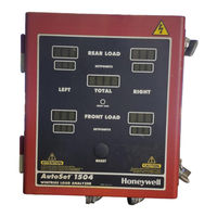
Wintriss autoset 1504 plus User Manual (102 pages)
load analyzer
Brand:
Wintriss
| Category:
Measuring Instruments
| Size: 2 MB
Table of Contents
Table of Contents
7
Chapter 1. Introduction
15
Standard Autoset Benefits
15
Autoset Plus Benefits
15
Autoset Front Panel
16
Figure 1-1. Autoset 1500 Front Panel
17
Figure 1-2. Autoset 1504 Plus Front Panel
17
Strain Links
18
Calibration
19
Autoset Operation
19
Autoset Faults
20
Autoset Specifications
20
Table 1-1. Autoset Specifications
20
Chapter 2. Installation
21
Mounting Autoset
21
Mounting an Autoset Enclosure
21
Figure 2-1. Autoset 1500 Mounting Dimensions
22
Figure 2-2. Autoset 1504 Mounting Dimensions
22
Installing an Autoset Panel Mount
23
Figure 2-3. Autoset Panel Mount: Mounting and Cutout Dimensions
24
Connecting AC and Stop Circuit Wiring
25
Figure 2-4. Autoset 1500 Processor Board: Location of Important Components
26
Figure 2-5. Autoset 1504 Processor Board: Location of Important Components
27
Figure 2-6. AC Power Connections
28
Table 2-1. AC Power and Stop Circuit Wiring Connections, TB103
28
Figure 2-7. Correct Way to Make Terminal Block Connections
29
Installing Strain Links
30
Mounting Strain Links
30
Figure 2-8. Strain Link: Mounting Dimensions
30
Table 2-2. Strain Link Part Numbers with Cable Length or Connector Type
30
Figure 2-9. Strain Link Mounting Options on Gap-Frame Presses
31
Figure 2-10. Strain Link Mounting Options on Straight-Side Presses
32
Figure 2-11. Strain Link Drill Jig: Mounting Dimensions
33
Wiring Strain Links
34
Table 2-3. Strain Link Connections on Autoset Processor Board
34
Table 2-4. Strain Link Wiring Connections, TB105 - TB108: Tension
35
Table 2-5. Strain Link Wiring Connections, TB105 - TB108: Compression
35
Installing a Zero Cam
36
Using a Zero Cam on Standard Autosets
36
Figure 2-12. Shield Drain Wire Connected to Ground Stud on Enclosure
36
Using a Zero Cam on Autoset Plus Units
37
Installing the Latching Magnetic Cam Switch (LMCS)
37
Figure 2-13. LMCS Installation
38
Table 2-6. LMCS (Zero Cam) Wiring Connections, TB101B or TB101A
39
Optional Wiring Connections
40
Wiring a Remote Reset Switch
40
Figure 2-14. Autoset 1504 Processor Board: Mode Switch #2 Set to on (Zero Cam Enabled)
40
Wiring an Oscilloscope
41
Table 2-7. Remote Reset Switch Wiring Connections, TB101B or TB101A
41
Wiring a Setup Mode Circuit (Autoset Plus Only)
42
Table 2-8. Oscilloscope Wiring Connections, TB101B or TB101A
42
Connecting an Autoset to Smartpac
43
Table 2-9. Setup Mode Circuit Wiring Connections, TB101B or TB101A
43
Figure 2-15. Autoset 1504 Processor Board: Mode Switch #6 Set to off (Autoset 1)
44
Connecting an Autoset to Smartpac 1
45
Table 2-11. Communications Wiring Connections: Autoset and Smartpac
47
Connecting AC Wires to Power Source
48
Powering up Autoset
48
Chapter 3. Calibration
49
Zeroing Strain Links
49
Figure 3-1. Potentiometer Adjustment Screw on Strain Links Without Access Hole in Cover
50
Table 3-1. Strain Link Potentiometer: Direction of Screw* Adjustment
51
Using a Voltmeter to Zero Strain Links
52
Recording Tonnage on an Autoset Calibration Kit
53
Setting up and Adjusting the Calibration Kit
53
Figure 3-2. Autoset 1500 Calibration Kit Processor Board: Old Style
54
Figure 3-3. Autoset 1500 Calibration Kit Processor Board: New Style
55
Figure 3-4. Tonnage Dial Indicators: Old-Style Board (Left), New-Style Board (Right)
57
Figure 3-5. Mode Switch #3 Set to "Decimal Point Off" Position (Old-Style Processor Board)
57
Figure 3-6. Load Cell Gain Adjustment Potentiometer with Adjustment Screw
58
Table 3-2. Autoset Load Cell Tonnage Display Formats
58
Applying Full-Scale Tonnage to the Calibration Kit
59
Setting Full-Scale Tonnage on Your Autoset
60
Figure 3-7. Autoset 1504 Processor Board: Tonnage Dial Indicators
61
Figure 3-8. Autoset 1504 Processor Board: Mode Switch #3 Set to off (Decimal Point On)
62
Table 3-3. Autoset 1500 and 1500 Plus Tonnage Display Formats
62
Adjusting Autoset to Read the Correct Tonnage
63
Table 3-4. Autoset 1504 and 1504 Plus Tonnage Display Formats
63
Figure 3-9. Autoset 1504 Processor Board: High/Low Gain Jumper and Gain Potentiometer
64
Table 3-5. Gain Adjustment Potentiometer and High/Low Gain Jumper Identifiers
64
Table 3-6. Autoset Load Readings: Ratio of Calibration Unit Readings
65
Checking Linearity
67
Figure 3-10. Autoset Label Showing Locations for Recording Calfactors and Jumper Settings
67
Final Checkout
68
Chapter 4. Operation
69
Autoset's Setpoint Calculation Process
69
Figure 4-1. Setpoint Calculation Example: Tonnage Produced at each Strain Link
70
Setting the Sample Period
71
Figure 4-2. Autoset 1504 Processor Board: Mode Switch #1 Set to off
72
Setting the Percent High Tolerance
73
Figure 4-3. Autoset 1504 Plus Processor Board: Percent High Tolerance Dial
73
Setting the Percent Repeatability Tolerance (Autoset Plus Only)
74
Table 4-1. Percent High Tolerance Selector Settings
74
Figure 4-4. Autoset 1504 Plus Processor Board: Percent Repeatability Dial
75
Table 4-2. Percent Repeatability Selector Settings
75
Determining the Correct High Tolerance Setting (Standard Autoset)
76
Determining the Correct High Tolerance and Repeatability Settings
77
Plus)
77
Determining the Correct High Tolerance and Repeatability Settings (Autoset Plus)
77
Changing Setpoint Percentage Settings
80
Recalculating Setpoints after a Tool Change
80
Displaying Reverse Load (Autoset Plus Only)
81
Figure 4-5. Autoset 1504 Plus Front Panel Showing Reverse Tonnage LED Displays
81
Four-Channel to Two-Channel Conversion
82
Disabling Autoset
82
Figure 4-6. Autoset 1504 Processor Board: Mode Switch #7 Set to on (2-Ch. Operation)
82
Turning off and Restoring Power
83
Chapter 5. Troubleshooting
85
Responding to Autoset Faults
85
High Tonnage Faults
86
Figure 5-1. Autoset 1504 Plus Front Panel Displaying High Setpoint Faults
86
Repeatability Faults
87
High Setpoint and Repeatability Faults
87
Figure 5-2. Autoset 1504 Plus Front Panel Displaying Repeatability Fault
87
Offset Errors
88
Figure 5-3. Autoset 1504 Plus Front Panel Displaying High Setpoint and Repeatability Faults
88
Troubleshooting Common Autoset Problems
89
Load or Setpoints LED Displays Are Blank
89
Figure 5-4. Autoset 1504 Plus Front Panel Displaying Offset Error
89
Front Load and Setpoints LED Displays Are Blank (4-Channel Units)
90
Load LED Display(S) Shows Zero Tonnage
90
Tonnage Shown in Load LED Displays Is too Low
90
New Installation or Calibration
90
Existing Installation
90
Using Leds as Diagnostic Tools
91
Remote Reset, Zero Cam, and Setup Leds
91
Reset, Repeatability Select, and Reverse Select Leds
91
Power Supply Leds, +5V and ±12V
92
Relay Status LED
92
Appendix A. Wiring and Settings Tables
93
Table A-1. AC Power and Stop Circuit Wiring Connections, TB103
93
Table A-2. Strain Link Wiring Connections, TB105 - TB108: Tension
93
Table A-3. Strain Link Wiring Connections, TB105 - TB108: Compression
93
Table A-4. TB101A and TB101B Wiring Connections
94
Table A-5. Mode Switch (S101) Settings
94
Table A-6. Percent High Tolerance Selector (S107) Settings
95
Table A-7. Percent Repeatability Selector (S106) Settings
95
Glossary
97
Index
99
Wintriss Manuals
101
Advertisement
Advertisement
Related Products
Wintriss autoset 1504
Wintriss autoset 1500
Wintriss autoset 1500 plus
Wintriss AutoSet PAC 120 VAC
Wintriss AutoSetPAC 24 VDC
Wintriss Categories
Controller
Industrial Equipment
Recording Equipment
Measuring Instruments
Network Card
More Wintriss Manuals
Login
Sign In
OR
Sign in with Facebook
Sign in with Google
Upload manual
Upload from disk
Upload from URL