Sign In
Upload
Manuals
Brands
Wincor Nixdorf Manuals
Payment Terminal
ProCash 2050xe USB
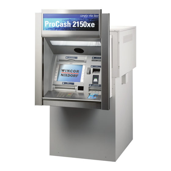
Wincor Nixdorf ProCash 2050xe USB Manuals
Manuals and User Guides for Wincor Nixdorf ProCash 2050xe USB. We have
1
Wincor Nixdorf ProCash 2050xe USB manual available for free PDF download: Installation Manual
Wincor Nixdorf ProCash 2050xe USB Installation Manual (202 pages)
Self-Service Systems
Brand:
Wincor Nixdorf
| Category:
Payment Terminal
| Size: 4.86 MB
Table of Contents
Table of Contents
5
Introduction
13
Symbols Used in this Manual
13
Important Safety Precautions
14
Installation Note
14
General Safety Precautions
14
Planning the Installation
19
Device Dimensions (35 MM (1.38") Tunnel)
19
Procash 2050Xe USB with 4-Cassette Dispenser
20
Device Without Illuminated Signage
20
Device with Illuminated Signage
22
Device with Illuminated Signage and Lower Light Case
23
Procash 2050Xe USB with 5-Cassette Dispenser
24
Device Without Illuminated Signage
24
Device with Illuminated Signage
25
Device with Illuminated Signage and Lower Light Case
26
Procash 2050Xe USB with 6-Cassette Dispenser
27
Device Without Illuminated Signage
27
Device with Illuminated Signage
28
Device with Illuminated Signage and Lower Light Case
29
Device Dimensions (60 MM (2.36") Tunnel)
30
Procash 2050Xe USB with 4-Cassette Dispenser
31
Device Without Illuminated Signage
31
Device with Illuminated Signage
32
Procash 2050Xe USB with 5-Cassette Dispenser
33
Device Without Illuminated Signage
33
Device with Illuminated Signage
34
Procash 2050Xe USB with 6-Cassette Dispenser
35
Device Without Illuminated Signage
35
Device with Illuminated Signage
36
Installation Options
37
Device View (35 MM (1.38") Tunnel)
38
Without Illuminated Signage
38
With Illuminated Signage
39
With Illuminated Signage and Lower Light Case
40
Device View (60 MM (2.36") Tunnel)
41
Without Illuminated Signage
41
With Illuminated Signage
42
Wall Cutout 4-Cassette and 5-Cassette Dispenser
43
Wall Cutout 6-Cassette Dispenser
44
Vents
45
Storage if Construction Work Is Not yet Complete
46
Space Required for Operation and Maintenance
46
Installation Options
49
Installation Options 4-Cassette Dispenser
49
Installation Options 5-Cassette Dispenser
52
Installation Option 6-Cassette Dispenser
55
Installation Site Requirements
56
Load-Carrying Capacity
56
Protection from Removal by Force in Compliance with en and Vds Guidelines
57
25 MM (0.98") Installation Frame
58
General Information
58
Securing the Installation Frame
58
Dimensions of Safe Attachment Points
59
Dimensions of Cable Areas
60
Calculating the Base Height
61
82 MM (3.23") Installation Frame
62
General Information
62
Securing the Installation Frame
62
Dimensions of Safe Attachment Points
63
Dimensions of Cable Areas
64
222 MM (8.74") Installation Frame
65
General Information
65
Securing the Installation Frame
66
Dimensions of Safe Attachment Points
67
Dimensions of Cable Areas
69
Height-Adjustable Installation Rack
71
General Information
71
Securing the Installation Rack
72
Dimensions of Safe Attachment Points
73
Dimensions of Cable Areas
75
Finding the Required Installation Rack
77
Tear-Off Sensor
79
Drilling Diagrams
79
Drilling Diagram for 25 MM (0.98") Installation Frame
80
Drilling Diagram for 82 MM (3.23") Installation Frame
81
Drilling Diagram for 222 MM (8.74") Install. Frame
82
Safe Width 600 MM (23.62")
82
Safe Width 450 MM (17.72")
83
Drilling Diagram for Height-Adjustable Installation Racks
84
Power and Data Cables
85
General Information
85
Power Supply
87
Remote Status Indicator
87
Dimensions of Illuminated Logos
88
Transport Path Requirements
89
Transport Measurements for Procash 2050Xe USB
90
Procash 2050Xe USB with 4-Cassette Dispenser
90
Procash 2050Xe USB with 5-Cassette Dispenser
92
Procash 2050Xe USB with 6-Cassette Dispenser
93
Example with Minimum Transport Path Measurements
96
Installation
99
Removing the Packaging
99
Removing the Shipping Crate
100
General Information
100
Removing the Shipping Crate
101
Mounting Sets
102
Mounting Set 01750006706 for Installation Frames or Installation Racks with UL Safe
102
Mounting Set 01750051579 for Installation Frames or Installation Racks with CEN III/IV Safe
103
Mounting Set 01750078516 (for UL / CEN L Safe) on 25 MM (0.98") Installation Frame
104
Mounting Set 01750051578 (for CEN III / CEN IV Safe) on 25 MM (0.98") Installation Frame
104
Mounting Set 01750051060 for Safe on 82 MM (3.23") and 222 MM (8.74") Installation Frames or Height-Adjustable Installation Racks
104
Overview of Installation Types
105
Installation with 25 MM (0.98") Installation Frame
106
Mounting the Installation Frame
106
Mounting the Device on the Installation Frame
112
Lifting the Cash Media Dispenser (CMD-V4) up
112
Screwing the Device on the Installation Frame
113
Pushing the Cash Media Dispenser (CMD-V4) down
114
Installing the Power and Data Cables in the Device
114
Further Procedure for CEN Installation
115
General Information
115
Installation with 82 MM (3.23") Installation Frame
116
Mounting the Installation Frame
116
Mounting the Device on the Installation Frame
121
Lifting the Cash Media Dispenser (CMD-V4) up
121
Screwing the Device on the Installation Frame
122
Pushing the Cash Media Dispenser (CMD-V4) down
123
Installing the Power and Data Cables in the Device
123
Further Procedure for CEN Installation
124
General Information
124
Installation with 222 MM (8.74") Installation Frame
125
Mounting the Installation Frame
125
Safe Width 600 MM (23.62")
127
Safe Width 450 MM (17.72")
128
General Information
129
Mounting the Device on the Installation Frame
132
Lifting the Cash Media Dispenser (CMD-V4) up
132
Screwing the Device on the Installation Frame
133
Pushing the Cash Media Dispenser (CMD-V4) down
134
Installing the Power and Data Cables in the Device
134
Further Procedure for CEN Installation
135
General Information
135
Installation with Height-Adjustable Installation Rack
136
Preparing the Installation Rack
137
Overview
137
Calculation of Rack Height
138
Mounting the Installation Rack
139
Installing the Bottom Part of the Installation Rack
139
Installing the Top Part of the Installation Rack
145
Mounting the Device on the Installation Rack
149
Lifting the Cash Media Dispenser (CMD-V4) up
149
Screwing the Device on the Installation Rack
150
Pushing the Cash Media Dispenser (CMD-V4) down
151
Installing the Power and Data Cables in the Device
151
Further Procedure for CEN Installation
152
General Information
152
Installing the Tunnel Frame
153
Pulling Out/Pushing in the Customer Panel
154
Installing the Sealing Frame
156
Installing the Adjusting Plates
158
Securing the Tunnel Frame
160
Connecting the Logo Light (Only on Tunnel Frames with Illuminated Signage)
162
Connecting the Tunnel Frame Light
164
Start-Up
165
Installing the Remote Status Indicator
167
Remote Status Indicator - Standard
167
Delivery Package
167
Installation
168
Connection to the Relay Panel for External Features
169
Remote Status Indicator - Audio
171
Delivery Package
171
Installation
172
Connection to the Relay Panel for External Features
174
Shortening the Cables
176
Adapting the Cable Length at the Relay Panel End
176
Adapting the Cable Length at the Standard Remote Status Indicator End
176
Adapting the Cable Length at the Remote Status Indicator (Audio)
179
Appendix
183
Check List for Installation Preparations for Self-Service Systems
183
General Information
184
Preparations
184
Construction Work
184
Power and Data Cables
185
Organizational Preparations
185
Delivery and Installation
186
Flooring Materials on the Path of Transport
186
Notes Concerning Installation Preparation
187
Technical Data
189
General Installation Conditions
189
Electrical Characteristics of the Supply Network
189
Device Conditions
190
Installation Specifications
192
Environmental Conditions
194
Compliance with Standards and Certification
196
Standards Met
196
Conformity
196
Notes Concerning Radio Interference Suppression and Electrical Safety
197
Certification for Data Transmission
197
FCC Rules and Canadian Standard ICES - 003
197
UL 291, Level 1 (Security Container)
198
Environmental Protection
198
Environmentally and Recycling-Friendly Product Development
198
Saving Energy
199
Disposing of Used Consumables
199
Labels on Plastic Case Parts
199
Returning, Recycling and Disposing of Used Units and Consumables
199
Advertisement
Advertisement
Related Products
Wincor Nixdorf Categories
Touch terminals
Monitor
Printer
Motherboard
Cash Register
More Wincor Nixdorf Manuals
Login
Sign In
OR
Sign in with Facebook
Sign in with Google
Upload manual
Upload from disk
Upload from URL