Sign In
Upload
Manuals
Brands
Wilo Manuals
Water Pump
CronoTwin-DL-E
Wilo CronoTwin-DL-E Manuals
Manuals and User Guides for Wilo CronoTwin-DL-E. We have
2
Wilo CronoTwin-DL-E manuals available for free PDF download: Installation And Operating Instructions Manual
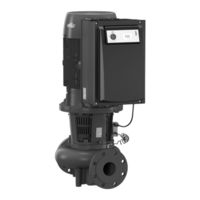
Wilo CronoTwin-DL-E Installation And Operating Instructions Manual (261 pages)
Brand:
Wilo
| Category:
Water Pump
| Size: 25 MB
Table of Contents
Deutsch
10
Table of Contents
10
1 Allgemeines
11
2 Sicherheit
11
Kennzeichnung von Hinweisen in der Betriebsanleitung
11
Personalqualifikation
12
Gefahren bei Nichtbeachtung der Sicherheitshinweise
12
Sicherheitsbewusstes Arbeiten
12
Sicherheitshinweise für den Betreiber
12
Sicherheitshinweise für Montage- und Wartungsarbeiten
12
Eigenmächtiger Umbau und Ersatzteilherstellung
13
Unzulässige Betriebsweisen
13
3 Transport und Zwischenlagerung
13
Versand
13
Transport für Montage-/Demontagezwecke
13
4 Bestimmungsgemäße Verwendung
14
5 Angaben über das Erzeugnis
14
Typenschlüssel
14
Technische Daten
15
Lieferumfang
16
Zubehör
16
6 Beschreibung und Funktion
17
Beschreibung des Produktes
17
Regelungsarten
18
Doppelpumpenfunktion/Hosenrohranwendung
19
Weitere Funktionen
22
7 Installation und Elektrischer Anschluss
24
Zulässige Einbaulagen und Änderung der Komponentenanordnung vor der Installation
25
Installation
27
Elektrischer Anschluss
30
8 Bedienung
36
Bedienelemente
36
Displayaufbau
37
Erläuterung Standardsymbole
37
Symbole in Grafiken/Anweisungen
38
Anzeigemodi
38
Bedienungsanweisungen
41
Referenz Menüelemente
44
9 Inbetriebnahme
51
Füllen und Entlüften
51
Doppelpumpeninstallation/Hosenrohrinstallation
52
Einstellung der Pumpenleistung
52
Einstellung der Regelungsart
53
10 Wartung
54
Luftzufuhr
55
Wartungsarbeiten
55
11 Störungen, Ursachen und Beseitigung
59
Mechanische Störungen
60
Fehlertabelle
61
Fehler Quittieren
63
12 Ersatzteile
68
13 Werkseinstellungen
69
14 Entsorgung
70
English
72
1 General Information
73
2 Safety
73
Symbols and Signal Words in the Operating Instructions
73
Personnel Qualifications
74
Danger in the Event of Non-Observance of the Safety Instructions
74
Safety Consciousness on the Job
74
Safety Instructions for the Operator
74
Safety Instructions for Installation and Maintenance Work
75
Unauthorised Modification and Manufacture of Spare Parts
75
Improper Use
75
3 Transport and Interim Storage
75
Shipping
75
Transport for Installation/Dismantling Purposes
75
4 Intended Use
76
5 Product Information
77
Type Key
77
Technical Data
77
Scope of Delivery
78
Accessories
78
6 Description and Function
79
Description of the Product
79
Control Modes
80
Dual Pump Function/Y-Pipe Application
81
Other Functions
84
7 Installation and Electrical Connection
86
Permitted Installations Position and Change of the Arrangement of Components before the Installation
87
Installation
89
Electrical Connection
92
8 Operation
98
Controls
98
Display Structure
99
Explanation of Standard Symbols
99
Symbols in Graphics/Instructions
100
Display Modes
100
Operating Instructions
103
Menu Elements Reference
106
9 Commissioning
113
Filling and Venting
113
Double Pump Installation/Y-Pipe Installation
114
Adjusting the Pump Output
114
Setting the Control Mode
115
10 Maintenance
116
Air Supply
117
Maintenance Work
117
11 Faults, Causes and Remedies
121
Mechanical Faults
122
Error Table
123
Acknowledge Fault
125
12 Spare Parts
130
13 Factory Settings
131
14 Disposal
132
Français
134
1 Généralités
135
2 Sécurité
135
Signalisation des Consignes de la Notice
135
Qualification du Personnel
136
Dangers Encourus en Cas de Non-Observation des Consignes
136
Travaux Dans Le Respect de la Sécurité
136
Consignes de Sécurité Pour L'utilisateur
136
Consignes de Sécurité Pour Les Travaux de Montage Et D'entretien
136
Modification du Matériel Et Utilisation de Pièces Détachées Non Agréées
137
Modes D'utilisation Non Autorisés
137
3 Transport Et Entreposage Intermédiaire
137
Expédition
137
Transport Pour Montage/Démontage
137
4 Utilisation Conforme
138
5 Informations Produit
138
Dénomination
138
Caractéristiques Techniques
139
Etendue de la Fourniture
140
Accessoires
140
6 Description Et Fonctionnement
141
Description du Produit
141
Types de Régulation
142
Fonction Pompe Double/Utilisation de Tuyau en y
143
Autres Fonctions
146
7 Montage Et Raccordement Électrique
148
Positions de Montage Autorisées Et Modification de la Disposition des Composants Avant L'installation
149
Montage
151
Raccordement Électrique
154
8 Commande
160
Eléments de Commande
160
Structure de L'écran
161
Explication des Symboles Standard
161
Symboles Sur Les Graphiques/Instructions
162
Modes D'affichage
162
Instructions de Commande
165
Référence des Éléments de Menu
168
9 Mise en Service
175
Remplissage Et Purge
175
Installation Pompe Double/Tuyau en y
176
Réglage de la Puissance de la Pompe
176
Réglage du Type de Régulation
177
10 Entretien
178
Arrivée D'air
179
Travaux D'entretien
179
11 Défauts, Causes Et Remèdes
183
Défauts Mécaniques
184
Tableau des Défauts
185
Acquitter un Défaut
187
12 Pièces de Rechange
192
13 Réglages D'usine
193
14 Elimination
194
Dutch
196
1 Algemeen
197
2 Veiligheid
197
Aanduiding Van Aanwijzingen in de Bedieningsvoorschriften
197
Personeelskwalificatie
198
Gevaren Bij de Niet-Naleving Van de Veiligheidsaanwijzigingen
198
Veilig Werken
198
Veiligheidsvoorschriften Voor de Gebruiker
198
Veiligheidsvoorschriften Voor Montage- en Onderhoudswerkzaamheden
199
Eigenmachtige Ombouw en Vervaardiging Van Reserveonderdelen
199
Ongeoorloofde Gebruikswijzen
199
3 Transport en Opslag
199
Verzending
199
Transport Voor Montage-/Demontagedoeleinden
199
4 Reglementair Gebruik
200
5 Productgegevens
201
Type-Aanduiding
201
Technische Gegevens
201
Leveringsomvang
202
Toebehoren
202
6 Beschrijving en Werking
203
Productomschrijving
203
Regelingstypes
204
Dubbelpompfunctie / Gebruik Y-Leiding
205
Overige Functies
208
7 Installatie en Elektrische Aansluiting
210
Toegestane Inbouwposities en Wijziging Van de Componentenopstelling Vóór de Installatie
211
Installatie
213
Elektrische Aansluiting
216
8 Bediening
222
Bedieningselementen
222
Opbouw Van Het Display
223
Toelichting Standaardsymbolen
223
Symbolen in Grafieken/Aanwijzingen
224
Weergavemodi
224
Bedieningsinstructies
227
Referentie Menu-Elementen
230
9 Inbedrijfname
237
Vullen en Ontluchten
237
Dubbelpompinstallatie/Y-Buisinstallatie
238
Instelling Van Het Pompvermogen
238
Instelling Van Het Regelingstype
239
10 Onderhoud
240
Luchttoevoer
241
Onderhoudswerkzaamheden
241
11 Storingen, Oorzaken en Oplossingen
245
Mechanische Storingen
246
Fouttabel
247
Fout Bevestigen
249
12 Reserveonderdelen
254
13 Fabrieksinstellingen
255
14 Afvoeren
256
Advertisement
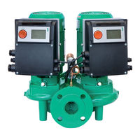
Wilo CronoTwin-DL-E Installation And Operating Instructions Manual (84 pages)
Module Modbus, Module BACnet
Brand:
Wilo
| Category:
Control Unit
| Size: 1 MB
Table of Contents
Table of Contents
5
Einbau- und Betriebsanleitung
7
GB Installation and Operating Instructions
22
F Notice de Montage Et de Mise en Service
37
E Instrucciones de Instalación y Funcionamiento
52
I Istruzioni DI Montaggio, Uso E Manutenzione
67
Advertisement
Related Products
Wilo CronoTwin-DL
Wilo Wilo-CronoTwin-DL Series
Wilo Wilo-CronoTwin-DL-E Series
Wilo CronoBloc-BL-E
Wilo Cronoline ICL
Wilo Cronoline
Wilo Wilo-CronoBloc-BL-E Series
Wilo Wilo-CronoLine-IL-E Series
Wilo Crono Series
Wilo Wilo-CronoBloc-BL Series
Wilo Categories
Water Pump
Industrial Equipment
Control Unit
Controller
Water System
More Wilo Manuals
Login
Sign In
OR
Sign in with Facebook
Sign in with Google
Upload manual
Upload from disk
Upload from URL