Sign In
Upload
Manuals
Brands
Weidmüller Manuals
I/O Systems
WI-I/O 9-U2 MESH I/O
User Manuals: Weidmüller WI-I/O 9-U2 MESH I/O Module
Manuals and User Guides for Weidmüller WI-I/O 9-U2 MESH I/O Module. We have
1
Weidmüller WI-I/O 9-U2 MESH I/O Module manual available for free PDF download: Manual
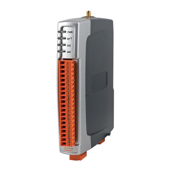
Weidmüller WI-I/O 9-U2 MESH I/O Manual (127 pages)
Industrial Wireless MESH I/O
Brand:
Weidmüller
| Category:
I/O Systems
| Size: 3 MB
Table of Contents
Table of Contents
7
Chapter 1 - Introduction
13
Overview
13
Module Structure
15
Figure 1 - Module Structure
15
Getting Started
16
Chapter 2 - Installation
16
General
17
Power/Supply
17
Requirements
17
Figure 2 - Power Connectors
17
Figure 3 - Supply Connections
17
Expansion I/O Supply
18
Internal I/O
19
Figure 4 - Expansion I/O Power & RS485
19
Grounding
20
Radio
21
900 Mhz Spread Spectrum Radio
21
Figure 5 - Earthing
21
869 Mhz Fixed Frequency Radio (EU Country Code)
22
Meshing Capability
22
Antenna
22
Dipole and Collinear Antennas
24
Figure 6 - Wrapping Coax Connections
24
Figure 7 - Collinear Antenna Mounting
25
Yagi Antennas
26
Figure 8 - Yagi Antenna Mounting
26
Connections
27
Bottom Panel Connections
27
Ethernet Port
27
USB Device Port for Configuration
27
Port
27
Figure 9 - Bottom Panel Connections
27
Port with Modbus Support
28
Side Access Configuration Panel
28
Factory Boot" Switch
28
Figure 10 - RS485 Connections
28
Figure 11 - Side Access Panel
28
Dipswitches
29
USB Host Port
29
Figure 12 - Front Panel Connections
30
Front Panel Connections
30
Digital / Pulsed Inputs
31
Figure 13 - Digital / Pulsed Input Wiring
31
Digital Outputs (Pulsed Outputs)
32
Digital Output Fail Safe Status
32
Figure 14 - Digital Output Wiring
32
Figure 15 - Digital Output Failsafe Times
33
Figure 16 - Fail-Safe State
33
Analog Inputs
34
Differential Current Inputs (AIN 1 & 2 Only)
34
Figure 17- Differential Current Inputs
34
Single Ended Current Inputs (AIN 3 & 4 Only)
35
Figure 18 - Single Ended Current Inputs
35
Figure 19 - Single Ended Current Inputs
35
Single Ended Voltage Inputs
36
Figure 20 - Voltage Inputs
36
Analog Outputs
37
Figure 21 - Analog Outputs
37
Chapter 3 - Operation
38
Overview
38
Indications
38
Front Panel Indications
38
Boot Sequence "PWR" LED Indications
39
Input / Output Indications
39
Digital Inputs
39
Digital Outputs
39
Figure 22 - Boot Sequence
39
Analog Inputs
40
Analog Outputs
40
Ethernet Indications
40
System Design
41
Radio Channel Capacity
41
Dual Band Operation
41
Radio Path Reliability
41
Design for Failures
42
Indicating a Communications Problem
43
Fail-To-Transmit Alarm
43
Fail-To-Receive Alarm
43
Wibnet - Communication Registers
43
Testing and Commissioning
44
Wibmesh
44
Chapter 4 - Configuration
46
First Time Configuration
46
Default IP Address
46
Changing PC Network Settings
46
Figure 23 - Network Settings
47
Figure 24 - Ping
47
Figure 25 - Main Welcome Screen
48
Over the Air Configuration
49
Figure 26 - IP Gateway Mode
49
Figure 27 - Default Gateway
49
Figure 28 -IP Address Range
49
Figure 29 - Routing Rule
50
Figure 30 -Over the Air Configuration
50
Module Configuration
51
Software & Connections
51
Re-Open Previous Project
52
Open Existing Project
52
Figure 31 - Installation
52
Figure 32 - Configuration Software
52
Create New Project
53
Configuration Screens
53
Project Tree
53
Configuration Display
53
Project Screen
53
Figure 33 - Configuration Screen
53
Password Protection
54
Project Information
54
Radio Communication Security
54
System Configuration
54
Adding Units
54
Create Units
54
Default Radio Network Configuration
54
Figure 34 - Project Information
54
Figure 35 - Create Units
54
Unit Details
55
IP Address List
55
Figure 36 - Unit Details
55
Mappings
56
Figure 37 - ID Address List
56
Figure 38 - Mappings
56
Gather Scatter Mapping
57
Mapping Configuration Parameters
57
Read Mappings
57
Write Mapping
57
Figure 39 - Gather/Scatter Mapping
58
Startup/Force Configuration
59
Example Configuration
60
Address Map
60
Figure 41 - Startup/Force Configuration
60
Standard WI-I/O 9-U2 I/O (Basic I/O)
61
I/O Configuration
62
Digital Inputs
62
Digital Outputs
62
Figure 42 - I/O Configuration
62
Figure 43 - Digital Inputs
62
Figure 44 - Digital Output
62
Pulsed Outputs
63
Analog Inputs
63
Figure 45 - Pulsed Outputs
63
Figure 46 - Analog Inputs Table
63
Figure 47- Analog Input
63
Analog Outputs
64
Figure 48 - Analog Output
64
Serial Expansion I/O
65
Adding Modules
65
WI-I/O-EX-1-S Expansion I/O Memory Map
65
Adding Expansion I/O to Configuration Software
66
Failsafe Blocks
66
Figure 49 - Expansion I/O
66
Invalid" Register State
67
Figure 50 - Failsafe Block Analog
67
Figure 51 - Failsafe Block Digital
67
Figure 52- Invalid Register State
67
Sensitivity Blocks
68
Figure 53 - Sensitivity Block
68
Serial Configuration
69
Modbus RTU Master
69
Figure 54 - Modbus TCP/RTU
69
Serial - Expansion I/O
70
Figure 55 - Expansion I/O
70
Serial - Modbus RTU Slave
71
Modbus Configuration
71
Modbus TCP Server & RTU Slave
71
Figure 56 - Modbus Configuration
71
Modbus TCP Client & RTU Master
72
Mapping Parameters
72
Figure 57 - Modbus TCP Client Mapping
72
Modbus TCP Mapping Examples
73
Figure 58 - Modbus TCP Mapping Table
73
Modbus RTU Master
74
Modbus RTU
74
Master Example
74
Figure 59 - Modbus RTU Example
74
RS232/RS485 Modbus Parameters
75
Figure 60 - Operating Mode Error
75
Figure 61 - Modbus Parameters
75
Web Based Configuration
76
Mesh
76
Figure 62 - Mesh Configuration
76
Neighbour RSSI Configuration
78
IP Routing
78
Figure 63 - Neighbour RSSI
78
Figure 64 - IP Routing
79
Radio Settings
80
Figure 65 - Radio Configuration Screen
80
Mesh Fixed Routes
81
Example #1
81
Figure 66 - Mesh Fixed Route#1
81
Figure 67 - Mesh Fixed Route - Gateway
82
Figure 68 - Mesh Fixed Route - Rep Site #2
82
Example #2
83
Figure 69 - Trace Route
83
Figure 70 - Mesh Fixed Route#2
83
Figure 71 - Mesh Fixed Route#2 Routing Rules
83
Module Information Web Page
85
Figure 72 - Module Information
85
System Tools Web Page
86
System Log File
86
Reading Configuration File
86
Writing Configuration File
86
Firmware Upgrade - Web Page (Patch File Upgrade)
86
Figure 73 - System Tools
86
Firmware Upgrade - USB (Full Firmware Upgrade)
87
Product Reconfiguration
89
Feature Licence Keys Web Page
90
Demonstration Mode
90
Feature Licence Keys
90
Chapter 5 - Diagnostics
91
IO Diagnostics
91
Watchdog Error Log
92
Module Information Registers
92
Expansion I/O Error Registers
92
Connectivity (Wibmesh)
93
LQI (Link Quality Indication)
95
Neighbour List (Wibmesh)
95
Neighbour RSSI (Wibmesh)
96
Network Diagnostics (Wibmesh)
97
Ping
97
Trace Route
98
Network Statistics (Wibmesh)
99
Monitor Comms
101
Wibmesh - Monitor Radio Comms
101
Wibmesh - Monitor IP Comms
102
Wibnet - Monitor Comms
103
Statistics (Wibmesh & Wibnet)
105
Chapter 6 - Specifications
106
Specifications
106
Appendix A: Dbm to Mw Conversion Table
109
Appendix B: I/O Store Registers
110
Appendix C: Expansion I/O Registers
113
Appendix D: Modbus Error Codes
115
Appendix E: Physical I/O Registers
117
Appendix F: Firmware Version Summary
121
Appendix G: Gnu Free Document Licence
124
Advertisement
Advertisement
Related Products
Weidmüller 9005610000
Weidmüller 9202040000
Weidmüller 9918950000
Weidmüller 9023100000
Weidmüller 9028500000
Weidmüller 9028530000
Weidmüller 9028540000
Weidmüller 9025300000
Weidmüller 9027310000
Weidmüller 9008120000
Weidmüller Categories
Switch
Crimp tool
Control Unit
Media Converter
Cables and connectors
More Weidmüller Manuals
Login
Sign In
OR
Sign in with Facebook
Sign in with Google
Upload manual
Upload from disk
Upload from URL