
Summary of Contents for Weidmüller WI-I/O 9-U2 MESH I/O
- Page 1 Industrial Wireless MESH I/O WI-I/O 9-U2 MESH I/O Manual Version 1.2.3 Feburary 2020 Read and Retain for Future Reference...
- Page 2 Weidmuller Inc. Corporate Headquarters 821 Southlake Boulevard Richmond, Virginia 23236 USA 804.794.2877 Main 800.849.9343 Customer & Technical Support 804.794.0252 Fax info@weidmuller.com Copyright Weidmüller Interface GmbH & Co. KG | Klingenbergstraße 16 | D-32758 Detmold Thank you for your selection of the WI-I/O 9-U2 I/O Module. We trust it will give you many years of valuable service.
- Page 3 GNU Free Documentation Licence: Copyright (C) 2009 Weidmuller. Weidmuller is using a part of Free Software code under the GNU General Public License in operating the “WI-I/O 9-U2” product. This General Public License applies to most of the Free Software Foundation’s code and to any other program whose authors commit by using it.
- Page 4 This WI-I/O 9-U2 module uses the “E2_900M Wireless Data Modem” radio and complies with Part 15.247 of the FCC Rules. Operation is subject to the following two conditions: • This device may not cause harmful interference • This device must accept any interference received, including interference that may cause undesired operation.
- Page 5 Hazardous Location Notices: This device complies with 94/9/EC – ATEX Directive Ex nA IIC T4A, II 3 G, –40 °C ≤ Ta ≤ +60 °C WARNING: EXPLOSION HAZARD. Do not disconnect equipment unless power has been switched off or the area is known to be non-hazardous.
- Page 6 IMPORTANT Notice: WEIDMULLER products are designed to be used in industrial environments, by experienced industrial engineering personnel with adequate knowledge of safety design considerations. WEIDMULLER radio products are used on unprotected license-free radio bands with radio noise and interference. The products are designed to operate in the presence of noise and interference, however in an extreme case, radio noise and interference could cause product operation delays or operation failure.
-
Page 7: Table Of Contents
TABLE OF CONTENTS CHAPTER 1 - INTRODUCTION ..................12 1.1 Overview ..............................12 1.2 Module Structure ............................14 1.3 Getting Started ............................15 CHAPTER 2 - INSTALLATION ................... 15 2.1 General ................................. 16 2.2 Power/Supply ............................... 16 2.2.1 Requirements ............................16 2.2.2 Expansion I/O Supply .......................... - Page 8 3.2.2 Boot Sequence “PWR” LED Indications ....................38 3.2.3 Input / Output Indications ........................38 Digital Inputs ............................... 38 Digital Outputs ............................38 Analog Inputs .............................. 39 Analog Outputs ............................39 3.2.4 Ethernet Indications ..........................39 3.3 System Design ............................. 40 3.3.1 Radio Channel Capacity ........................
- Page 9 Digital Outputs ............................61 Pulsed Outputs ............................62 Analog Inputs .............................. 62 Analog Outputs ............................63 4.3.10 Serial Expansion I/O ..........................64 Adding modules ............................64 WI-I/O-EX-1-S Expansion I/O Memory Map ....................64 Adding Expansion I/O to Configuration Software ..................65 4.3.11 Failsafe Blocks .............................
- Page 10 5.5 Network Diagnostics (WibMesh) ....................... 96 Ping ................................96 Trace Route ..............................97 5.6 Network Statistics (WibMesh) ........................98 5.7 Monitor Comms ............................100 5.7.1 WibMesh – Monitor Radio Comms ...................... 100 5.7.2 WibMesh - Monitor IP Comms ......................101 5.7.3 WibNet –...
- Page 11 Figure 37 - ID Address List ......55 TABLE OF FIGURES Figure 38 - Mappings ........55 Figure 1 – Module Structure Figure 39 - Gather/Scatter Mapping ....57 Figure 2 – Power Connectors ......16 Figure 40 - Startup/Force . Error! Bookmark not Figure 3 –...
- Page 12 Figure 74 - Format USB ........86 Figure 75 - Quick Format ........ 86 Figure 76 - Firmware Files ......86 Figure 77- firmware version ......87 Figure 78 - Side access panel......87 Figure 79 - Firmware Upgrade LED Indications ............
-
Page 13: Chapter 1 - Introduction
Chapter 1 - Introduction 1.1 Overview The WI-I/O 9-U2 range of I/O modules has been designed to provide standard “off-the- shelf” telemetry functions, for an economic price. Telemetry is the transmission of data or signals over a long distance via radio or twisted-pair wire cable. Although the WI-I/O 9-U2 Series is intended to be simple in its application, it provides many sophisticated features, which will be explained in the following chapters. - Page 14 The WI-I/O 9-U2 modules transmit the input/output data using radio or Ethernet. The data frame includes the "address" of the transmitting module and the receiving module, so that each transmitted message is acted on only by the correct receiving unit. Each message includes error checking to ensure that no corruption of the data frame has occurred due to noise or interference.
-
Page 15: Module Structure
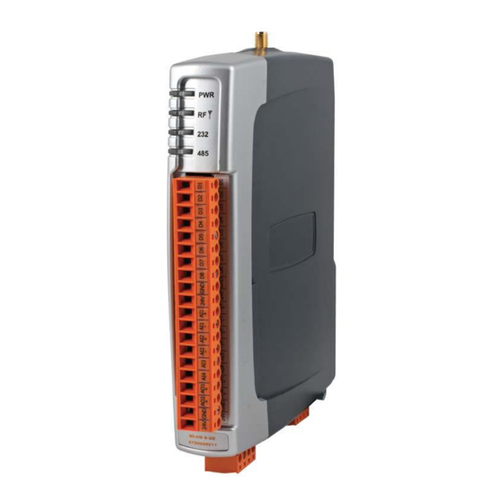
1.2 Module Structure WI-I/O 9-U2 Figure 1 – Module Structure The WI-I/O 9-U2 is made up of a number of basic sections, which all interface with a central Input and output storage area (I/O Store). The I/O Data Store provides storage for I/O data as well as providing services to other processes in the system. -
Page 16: Getting Started
There are also a number of Internal I/O that can be accessed from the I/O Data Store. These inputs can be used to interpret the status of a single module or an entire system • Battery voltage – The battery terminal voltage displayed as an Analog value. •... -
Page 17: General
2.1 General All WI-I/O 9-U2 Series modules are housed in a plastic enclosure with DIN rail mounting, providing options for up to 14 I/O points, and separate power & communications connectors. The enclosure measures 170 x 150 x 33 mm including connectors. -
Page 18: Expansion I/O Supply
The Supply and Battery charging terminals are hosted on the 4-way connector on the bottom edge of the module labelled “Supply” Both Supply and Battery connections have reverse polarity and over voltage protection. The power supply should be CSA Certified Class 2 approved for normal operation. If the device is being used in a Class I Div 2 explosive area, the supply must have Class I Div 2 approval. -
Page 19: Internal I/O
Figure 4 – Expansion I/O power & RS485 As a guide when using the I/O power connection from the WI-I/O 9-U2, the number of I/O modules is limited to three x WI-I/O-EX-1-S-11(using inputs), one x WI-I/O-EX-1-S- 12, or one x WI-I/O-EX-1-S-13. If more I/O Modules are required, you will need to calculate the overall current consumption using the following criteria and power the modules from an external supply. -
Page 20: Grounding
Local 24V loop voltage (0-40V scaling) – Internally generated +24V 30006 supply used for analog loop supply. Maximum Current limit is 100mA 30007 Local Battery voltage (0-40V scaling) 30008 WI-I/O-EX-1-S Supply Voltage (0-40V scaling) 38005 – 38008 Floating Point Registers, also indicate the Supply voltage, Battery Voltage, +24V Supply and WI-I/O-EX-1-S Supply voltages but in a voltage scale. -
Page 21: Radio
Figure 5 - Earthing 2.3 Radio The following radio variants are available in the WI-I/O 9-U2 dependent on the country of operation. 2.3.1 900 MHz Spread Spectrum radio The radio uses frequency hopping spread spectrum modulation, which is a method of transmitting radio signals by switching the carrier among many frequency channels, using a pseudo random sequence called a hop set. -
Page 22: 869 Mhz Fixed Frequency Radio (Eu Country Code)
• Spread-spectrum signals are more resistant to narrowband interference. • They are difficult to intercept or eavesdrop because of the pseudorandom transmission sequences. • Transmissions can share a frequency band with other types of conventional transmissions with minimal interference. 2.3.2 869 MHz Fixed Frequency radio (EU Country Code) This radio operates in the unlicensed fixed frequency band of 869 MHz. - Page 23 • USA/Canada 15 miles - 6dB net gain antenna configuration permitted (4W EIRP) • Australia/NZ 12 km - Unity gain antenna configuration (1W EIRP) To achieve the maximum transmission distance, the antennas should be raised above intermediate obstructions so the radio path is true “line of sight”. Because of the curvature of the earth, the antennas will need to be elevated at least 15 feet (5 metres) above ground for paths greater than 3 miles (5 km).
-
Page 24: Dipole And Collinear Antennas
An antenna should be connected to the module via 50 ohm coaxial cable (e.g. RG58, RG213, Cellfoil, etc) terminated with a male SMA coaxial connector. The higher the antenna is mounted, the greater the transmission range will be, however as the length of coaxial cable increases so do cable losses. -
Page 25: Figure 7 - Collinear Antenna Mounting
Figure 7 – Collinear Antenna mounting... -
Page 26: Yagi Antennas
Yagi antennas. A Yagi antenna provides high gain in the forward direction, but lower gain in other directions. This may be used to compensate for coaxial cable loss for installations with marginal radio path. The Yagi gain also acts on the receiver, so adding Yagi antennas at both ends of a link provides a double improvement. -
Page 27: Connections
2.5 Connections 2.5.1 Bottom panel connections Figure 9 – Bottom Panel Connections Ethernet port The WI-I/O 9-U2 modules provides a standard RJ-45 Ethernet port compliant to IEEE 802.3 10/100 BaseT. This port provides full access to the module, including configuration, diagnostics, log file download and firmware upload, of both the local and remote units. -
Page 28: Port With Modbus Support
RS-485 port with Modbus Support. The WI-I/O 9-U2 module provides an RS-485 serial port, which supports operations at data rates up to 230,400 baud. Default baud rate is 9600 baud, No Parity, 8 data bits and 1 stop bit which match the WI-I/O-EX-1-S serial expansion modules defaults. This port Supports MODBUS protocol. -
Page 29: Usb Host Port
The “Factory Boot” switch is used for factory setup and diagnostics. This switch should not normally be used, except if advised by WEIDMULLER support. USB Host port This port is a USB Host (Master port), which can interface with USB storage devices for data logging (Future) and for upgrading the module Firmware –... -
Page 30: Front Panel Connections
Front panel connections Figure 12 – Front Panel Connections The WI-I/O 9-U2 front panel provides connections for the following • Eight Digital Input /Output (DIO1-8). • Two 12 bit, 0.1% accuracy differential analog inputs. • Two single ended 12 bit, 0.1% accuracy analog inputs. •... -
Page 31: Digital / Pulsed Inputs
2.5.3 Digital / Pulsed Inputs Each digital I/O channel on the WI-I/O 9-U2 can act as either an input or an output. The input/output direction is automatically determined by the connections and configuration of the I/O. If you have an I/O channel wired as an input but operate the channel as an output. No electrical damage will occur however, the I/O system will not operate correctly. -
Page 32: Digital Outputs (Pulsed Outputs)
2.5.4 Digital Outputs (Pulsed Outputs) Digital outputs are open-collector transistors and are able to switch loads up to 30VDC, 200mA. The 8 digital outputs share the same terminals as the digital input. These terminals are marked D1-8. WI-IO 9-U2 Figure 14 – Digital Output Wiring When active, the digital outputs provide a transistor switch to EARTH (Common). -
Page 33: Figure 15 - Digital Output Failsafe Times
Figure 15 – Digital Output Failsafe Times The Fail Safe Time is the time the output counts down before activating a Fail Safe state. Normally this would be configured for a little more than twice the update time of the mapping that is sending data to it. -
Page 34: Analog Inputs
2.5.5 Analog Inputs The WI-I/O 9-U2 provides two floating differential analog inputs and two grounded single-ended analog inputs. Analog Input 1 & 2 will automatically measure Current (0-20 mA) or Voltage (0-25V) depending on what is connected to the input. Analog input 3 &... -
Page 35: Single Ended Current Inputs (Ain 3 & 4 Only)
Figure 18 – Single Ended Current Inputs Single Ended Current Inputs (AIN 3 & 4 only) Single-ended current input mode is useful if the sensor loop is grounded to the WI-I/O 9- U2 module. Devices can be powered from the 24V Analog Loop Supply (ALS) generated internally from the module. -
Page 36: Single Ended Voltage Inputs
Single Ended Voltage Inputs All analog inputs can be setup to read voltage. If using Analog input 1 & 2 connect the voltage source across the positive terminal of the input and Common. If using Analog input 3 & 4 then connect across the input terminal and Common. Note: Default scaling gives 0-20V for 4-20mA output on Analog 1 and 2. -
Page 37: Analog Outputs
2.5.6 Analog Outputs The WI-I/O 9-U2 module provides two 0 - 24 mA DC analog outputs for connecting to analog inputs on equipment such as PLC’s, DCS, Loggers, etc. or connecting to instrument indicators for the display of remote analog measurements. The WI-I/O 9-U2 Analog outputs are a sourcing output and should be connected from the analog output terminal through the device or indicator to Common. -
Page 38: Chapter 3 - Operation
Chapter 3 - Operation Overview The WI-I/O 9-U2 range of I/O modules has been designed to provide standard “off-the- shelf” telemetry functions, at an economic price. Telemetry is the transmission of data or signals over a long distance via radio or twisted-pair wire cable. 3.2 Indications When power is initially connected to the module it will perform some internal setup and diagnostics checks to determine if the module is operating correctly. -
Page 39: Boot Sequence "Pwr" Led Indications
3.2.2 Boot Sequence “PWR” LED Indications Figure 22 - Boot Sequence 3.2.3 Input / Output Indications Condition Meaning Indicator D 1- 8 ORANGE Digital input ON FLASHING ORANGE - Update Failure - Failsafe state D 1- 8 (Long On) FLASHING ORANGE - Update Failure - Failsafe state D 1- 8 (Long Off) -
Page 40: Analog Inputs
Analog Inputs Two LEDs exist for each Differential analog input. The first LED (+) is used to indicate the analogue input is reading a Current (mA), the second LED (-) indicates the input is reading Voltage. Each of the analog input LEDs will flash with increasing speed and intensity depending on the level of the input (4mA = slow/dim and 20mA= fast/bright) For each of the single ended analog channels, the LED indicates when the input is reading Current or Voltage by flashing the LED with the level of the input (4mA =... -
Page 41: System Design
3.3 System Design 3.3.1 Radio Channel Capacity Messages sent on a cable link are much faster than on a radio channel, and the capacity of the radio channel must be considered when designing a system. This becomes more important as the I/O size of a system increases. The modules are designed to provide “real-time”... -
Page 42: Design For Failures
antennas to be elevated at least 13 feet (4m) to achieve “line-of-sight” even if the path is flat. A radio path may act reliably in good weather, but poorly in bad weather - this is called a “marginal” radio path. If the radio path is more than 20% of the maximum reliable distance (see Specification section for these distances), we recommend that you test the radio path before installation. -
Page 43: Indicating A Communications Problem
• A module can provide an output, which activates on communication failure to another module. This can be used to provide an external alarm that there is a system fault. 3.3.5 Indicating a Communications Problem There are two ways to indicate communications problems. Fail-to-transmit alarm The first method is to setup a communications indication on a register of your choice when configuring a mapping. -
Page 44: Testing And Commissioning
General purpose digital registers 10501 to 10595 will indicate a communication fail for the corresponding remote radio address. E.g. Address 10505 will indicate a communication fail for remote address # 5 Address 10590 will indicate a communications failure for remote address # 90. Note: Radio must have a valid mapping for the remote address and the mapping must have the ‘ACK’... - Page 45 When a link fails, a routing error is passed back to a transmitting node, and the process repeats.
-
Page 46: Chapter 4 - Configuration
Chapter 4 - Configuration 4.1 First time Configuration The WI-I/O 9-U2 has a built-in web server, containing web pages for analysing and minor modification to the module’s configuration. The configuration can be accessed ® using any web browser however we recommend using Microsoft Internet Explorer 8. -
Page 47: Figure 23 - Network Settings
Open “Properties” of Local Area Connection. Select Internet Protocol (TCP/IP) and click on Properties. On the General tab, enter IP address 192.168.0.1, Subnet mask 255.255.255.0 and press “OK” Figure 23 – Network Settings The simplest way to check Ethernet communications is to use the “Ping” command From the Windows Start menu, select “Run”... -
Page 48: Figure 25 - Main Welcome Screen
This option may be modified by opening Tools -> Internet Options -> Connections Tab - > LAN Settings->Proxy Server -> bypass proxy for local addresses. Enter the default IP address for the WI-I/O 9-U2 https://192.168.0.1XX where XX is the last two digits of the serial number. Enter the username “user”... -
Page 49: Over The Air Configuration
4.2 Over the Air Configuration The WIBMesh WI-I/O 9-U2 modules communicate using Standard Ethernet Protocols which make it possible to connect to other WI-I/O 9-U2 modules within the radio network for over the air diagnostics and configuration changes. A little forethought when designing the system is required as some minor configuration settings need to implemented for ‘Over the air’... -
Page 50: Figure 29 - Routing Rule
Address can be changed by going to the ‘Ethernet’ branch on the Project tree of the configuration software for each of the remote modules. 4. The PC must have its Default Gateway address set to the Central WI-I/O 9-U2’s Ethernet IP Address or have a routing rule added to its default routing table, e.g. -
Page 51: Module Configuration
4.3 Module Configuration Module configuration can be done using the WI Mesh utility for Meshing and Econfig for Legacy or via inbuilt web pages. We recommend the software be used as the primary config as is easier to use and simplifies the overall configuration. It is also project based which means you can group a number of modules in one configuration file. -
Page 52: Re-Open Previous Project
Figure 31 - Installation Figure 32 – Configuration Software When the Confiugration Utility has been installed and run you are presented with 3 options, 1. Re-Open Previous Project, 2. Open Exisitng Project, 3. Create New Project. Re-Open Previous Project When selected, this will open the last used project on this PC. Typically all configuration project files are stored locally on the used PC or a Network drive. -
Page 53: Create New Project
created elsewhere and sent to you. A dialog box will appear to navigate to the saved project that you wish to open. Create New Project When selected, this will allow you to start a new configuration project. It will allow you to name the project and also specify a directory location to save it to. -
Page 54: Project Information
the name of the project. Selecting the project name will display the following. Project Information This details the project name and the directory location of the project. The Project name can be changed if need be from this area. Password Protection Figure 34 - Project Information Password protection is used to provide a security option to the project itself. -
Page 55: Unit Details
increment as each radio is added to the configuration. Typically this IP address range does not need to be changed as only WIBMesh Protocol radios can communicate to each other, that is even though the WIBMesh protocol is based around an IP Standards based protocol, it is still not an open standard like Wi-Fi which means you cannot directly connect to the WI-I/O 9-U2 via your PC. -
Page 56: Mappings
Figure 37 - ID Address List The configuration screen for this option is a read only screen. All parameters for this can only be edited from the radio selection itself. 4.3.5 Mappings Mappings are used to send I/O values between WI-I/O 9-U2 modules. The I/O is typically sent via the Radio interface however at times it can be used to be sent via the Ethernet interface between modules. -
Page 57: Write Mapping
It should be noted that the ‘Updates’ are only a check signal and care should be taken when configuring the update values with short update times (< 5 seconds) as it will greatly increase the amount of radio traffic. There are three different types of mappings, Write, Gather/Scatter and Read Mappings, which are explained below. -
Page 58: Figure 39 - Gather/Scatter Mapping
Figure 39 - Gather/Scatter Mapping Destination – Shows two standard choices as well as a radio IP and an Ethernet IP address for each module in the project. The first choice is ‘Local Host’ which is the standard name given to the address of the loopback network interface and basically means the module you are currently configuring (itself). -
Page 59: Startup/Force Configuration
Update Time - This is the period of time that the mapping update messages (check signal) are sent. This is outside of the normal change of state updates that occur when an input changes. Offset Time - Configures an offset time for the update mapping. It is used to stagger the update transmissions so on start-up and every update period the module does not send all mapping at the same time. -
Page 60: Example Configuration
To ensure the module outputs get updated with the latest remote input status when first powered on we can configure the module to transmit a special “start-up /force” message which will write a value into an internal register at the remote module/s. The remote module/s can then use this register to force any mappings it has configured for the destination. -
Page 61: Standard Wi-I/O 9-U2 I/O (Basic I/O)
Type Size Address discrete outputs 3000 (bits) 00001 discrete inputs 2500 (bits) 10001 Word (unsigned) inputs (16-bit) 2500 (words) 30001 word (unsigned) outputs(16-bit) 2500 (words) 40001 long inputs (32-bit) 20 (longwords) 36001 float inputs (32-bit) 20 (floats) 38001 long outputs (32-bit) 20 (longwords) 46001 float outputs (32-bit) -
Page 62: I/O Configuration
Local AO1 – AO2 as floating point values (mA) 48001 - 48002 4.3.9 I/O Configuration I/O configuration is done using the Configuration software and each I/O has different characteristics that can be tailored to certain applications. Selecting IO from within the Project Tree in the Configuration utility will display configuration options for the I/O, the configuration display (explained below) will... -
Page 63: Pulsed Outputs
If the Failsafe state is enabled (ON) this will indicate with the LED flashing briefly OFF and the digital output will turn on. If the Failsafe state is disabled (OFF) this will indicate with the LED flashing briefly ON and the digital output will turn off. Pulsed Outputs Name –... -
Page 64: Analog Outputs
• Zero – Starting Value (counts) when measured value is zero • Span – Number of counts per measured value (mA, V, Hz, etc) The Analog is a linear scale with an overall raw range of 8192 to 49152 decimal (Total = 40960). -
Page 65: Serial Expansion I/O
Failsafe value (mA) – The value that you wish the output to be set to on completion of the failsafe timeout. 4.3.10 Serial Expansion I/O Adding modules Additional WI-I/O-EX-1-S serial expansion I/O modules can be added if more I/O is required. -
Page 66: Adding Expansion I/O To Configuration Software
• Analog input 1 will be at register location 30321 See Appendix C: “Expansion I/O Registers”. For a more detailed address map of the serial expansion I/O modules. When adding expansion I/O modules to the WI-I/O 9-U2, there are two inbuilt register associated to indicating the communication status of the expansion I/O module. -
Page 67: Invalid" Register State
Figure 49 - Failsafe Block Analog Figure 50 - Failsafe Block Digital In Figure 50 - Failsafe Block Digital’ above, register 40501 holds an analog value that has been mapped from another module and is updated every 60 seconds. The configuration is configured so that on start-up the module will write a value of 16384 into register 40501 and then start counting down the “Fail Timeout”... -
Page 68: Sensitivity Blocks
If you were to read the registers using the “I/O Diagnostics” an invalid register would read “~“ as shown in Figure 51 above. Any mapping with an invalid register will be inhibited from sending. This is to ensure the data that gets to the destination is valid and not just default values that the module starts up with. -
Page 69: Serial Configuration
4.3.13 Serial Configuration The WI-I/O 9-U2 has an RS-232, and an RS-485 port for serial communications. These ports are used to connect WEIDMULLER WI-I/O-EX-1-S-11, WI-I/O-EX-1-S-12 & WI-I/O-EX-1-S-13 serial expansion I/O modules. The ports can also be used to connect external Modbus RTU Master or Slave devices The port Operating Mode and the normal serial parameters, Baud Rate, Data Format, Flow Control, etc. -
Page 70: Serial - Expansion I/O
Request Pause – Is the delay between serial requests in milliseconds Response Wait – Is the serial response timeout in milliseconds – a serial retry will be sent if a response is not received within this timeout. Connection Timeout – Is the TCP connection timeout in seconds – if no Modbus/TCP data is received within this timeout then the TCP connection will be dropped. -
Page 71: Serial - Modbus Rtu Slave
Maximum Tries – Is the maximum number of request retries performed on the serial port. Serial - Modbus RTU Slave When configured as a Modbus RTU slave the only parameter that will need to be configured are the Date Rate, Data Format and Flow Control. 4.3.14 Modbus Configuration The WI-I/O 9-U2 provides Modbus TCP Client/ Server &... -
Page 72: Modbus Tcp Client & Rtu Master
‘Device ID’ Is the Device ID for the modules own Modbus Server/Slave. This is the ID that and external Modbus Client or Modbus Master would require to allow it to read values from the internal Modbus registers, i.e. if a DCS or Scada computer needed to poll the WI-I/O 9-U2 via TCP or serial connection. -
Page 73: Modbus Tcp Mapping Examples
Local Register (Master) – When the Function Code (Command) is ‘Read’ the ‘Local Register’ will be the destination register or output location on the Local device, when the Function Code (Command) is a ‘Write’ the ‘Local Register’ will be the originating register or input location on the local device. -
Page 74: Modbus Rtu Master
server Port is 502, which is a standard Modbus TCP Port address and if the mapping fails to communicate to the TCP server it will write a value of 1 into local register 508 indicating a communications failure. The next mapping shows something similar however, instead of analog value they are digital values. -
Page 75: Rs232/Rs485 Modbus Parameters
The first mapping shows a read mapping from a serial device connected on the RS485 port with a Device ID of 5. It’s reading 1 I/O point starting at remote address 30001 and writing the value into the local address 40501. It’s configured with a response timeout of 1000mSec and local register 508 will indicate a failure to communicate with this device. -
Page 76: Web Based Configuration
4.4 Web based Configuration Some configuration options are available by web based configuration only. If utilising these option they will need to be accessed using a web browser and connecting to the modules IP Address, i.e. 192.168.0.XXX 4.4.1 Mesh Figure 61 - Mesh Configuration Enabling this option will allow communicating modules access to an external Ethernet Network if connected (IP address range configured under Network Settings). - Page 77 in an environment that is known to have multipath fading. These installations are typically where units are installed inside buildings or in environment where antenna do not have uninterrupted line of sight or have large metallic objects that are close to the antennas. The multipath RSSI algorithm calculates a path RSSI that will be used when establishing mesh links between neighbours.
-
Page 78: Neighbour Rssi Configuration
4.4.2 Neighbour RSSI configuration RSSI values from neighbouring devices can be stored in register. Configuring is done from this web page. The Neighbour RSSI values can be mapped to a register of your choosing. A maximum number of 100 neighbours can be configured and any analog register can be used to store the value. -
Page 79: Figure 64 - Ip Routing
interfaces (i.e. hard-wired Ethernet, or Radio) and forwards the frame appropriately. However, if the IP network address does not match the network address of any of its interfaces, the WI-I/O 9-U2 will forward the frame to its default gateway. In this case it is assumed that the default gateway has a valid route to the destination. -
Page 80: Radio Settings
4.4.4 Radio Settings Select the “Radio” Menu to change the following configuration parameters. If a change is made, you need to select “Save Changes” to retain the changes. Changes will not take effect until the unit is reset. Figure 64 – Radio Configuration Screen Radio Settings A unique address that is used to differentiate one wireless system from another, All radios that are required to communicate within the... -
Page 81: Mesh Fixed Routes
Transmit Power Adjust the Transmit power level from 30dB (1 W) to 20dB (100 mW). Mode See dBm to mW conversion table at Appendix A: A selection of data rates is available depending on the country code. Fixed Frequency model (EU) can use 14, 38, 56 and 76kbps while the FHSS (US, AU, NZ and IN) use 19, 56, 76 and 115kbps. -
Page 82: Figure 67 - Mesh Fixed Route - Gateway
communicate via this path regardless of the signal quality. When Setting up Mesh Fixed Routes each site that is being mapped to will require a route to be configured for the Destination and the Next address. Figure 66 - Mesh Fixed Route - Gateway Figure 67 - Mesh Fixed Route - Rep Site #2 show the Mesh Fixed Routing Rules in the Gateway for the network diagram in Figure 65. -
Page 83: Example #2
via 10.0.0.2 (site #2) and 10.0.0.3 Site #3) Example Figure 68 - Trace Route Figure 69 - Mesh Fixed Route#2 Figure 70 – Mesh Fixed Route#2 Routing Rules The first route shows the destination and next addresses are both 10.0.0.1 as it’s a single hop. - Page 84 External Indicates that it is routed through a Gateway outside of the mesh Check this box to enable the rule. You can Uncheck the box to Enabled disable a routing rule without needing to re-enter the information at a later time. Save Changes Save changes to non-volatile memory, and restarting the function to and Activate.
-
Page 85: Module Information Web Page
4.4.6 Module Information Web Page This Web page is primarily for information purposes. With the exception of the password, the information entered here is displayed on the home configuration webpage of the WI-I/O 9-U2. Figure 71 - Module Information Configuration of Username. This is the username used to access Username the configuration on the WI-I/O 9-U2. -
Page 86: System Tools Web Page
4.4.7 System Tools Web page Figure 72 – System Tools System Log File Logs system instructions, etc to the screen where the log screen can be saved to a file. Not normally used, however maybe used by Technical Support to diagnose problems. The “Clear System Log”... -
Page 87: Firmware Upgrade - Usb (Full Firmware Upgrade)
Firmware Upgrade – USB (Full Firmware Upgrade) Firmware can also be upgraded using a USB flash drive with the firmware files installed. Typically a full USB upgrade is required if the existing firmware is a much older version and would requires multiple patch files to upgrade to the latest version or a patch file may not be available. - Page 88 Upgrade Procedure 1. Prior to performing upgrade note the current firmware version of the WI-I/O 9- U2 by connecting to the modules home webpage. This will allow you to compare this version with the final version to confirm the upgrade procedure has been performed successfully.
-
Page 89: Product Reconfiguration
Product Reconfiguration Changes the operating mode between WIBMesh and WIBNet. WIBNet is a compatibility mode that will allow communications between the WI-I/O 9-U2 and earlier WEIDMULLER WI-Series Telemetry units, e.g. WI-I/O 9-X-1, 2, 3, 4, C, G, K, L, etc. Figure 79 - Product Reconfiguration The Dropdown box has two selections, Meshing Mode - Standard Weidmuller WIBMesh and is the format that the module will... -
Page 90: Feature Licence Keys Web Page
4.4.8 Feature Licence Keys Web Page Allows the module to be upgraded with enhanced features or upgraded to a more advanced model .i.e. enabling the Modbus option. The Feature Licence unlock codes are purchasable by contacting Weidmuller or your local distributor. The module serial number is needed to generate the Feature Licence Key. -
Page 91: Chapter 5 - Diagnostics
Chapter 5 - Diagnostics 5.1 IO Diagnostics Figure 83- I/O Diagnostics Selecting this option from the main screen will allow some basic reading and writing of the I/O store registers within the module. To read a register location, enter an address location, e.g. 10001 (for digital Inputs), enter a count (number of consecutive registers) and then press the “Read”... -
Page 92: Watchdog Error Log
5.1.1 Watchdog Error Log The module uses a number of different processes to control aspects of the internal workings of the module, i.e. Radio operation, I/O functionality, AODV communications, Modbus Communications, etc. Each process runs independent of each other and can interact with the other processes to provide a robust wireless I/O product. -
Page 93: Connectivity (Wibmesh)
30017 + Offset = Modbus Error Counter (number of errors the modules has had) 30018 + Offset = Last WI-I/O-EX-1-S Status Code / Modbus Error Code. Will display the following WI-I/O-EX-1-S Status Codes (Hex code 1-5 & 129), as well as the standard Modbus Response Codes shown in Appendix D with a slight difference in the code. - Page 94 and link quality along with some message related information. The readings shown are based upon the last received data message from the device. Figure 84 - Connectivity Note that when updating the Connectivity webpage; ensure the page is current by refreshing the page.
-
Page 95: Lqi (Link Quality Indication)
Addition indications for this entry. G=Gateway, F=Fixed, E=External Gateway: This unit is a gateway to provide access outside of the radio network. Flags Fixed: Manually configured route. External: Accesses a device outside the local network. Iface The connection interface (er0 = Ethernet radio, eth0 = Ethernet LAN) Age (H:M:S) This is the timeout of the message in Hours, Minutes, Seconds LQI (Link Quality Indication) -
Page 96: Neighbour Rssi (Wibmesh)
5.4 Neighbour RSSI (WibMesh) Figure 86 - Neighbour RSSI Shows the receive signal strength on each of the 50 available channels within the frequency band. To find out if the path between two neighbouring units has a multipath fading issue, enter the radio IP address of the neighbour you wish to view and press “Get Graph”. -
Page 97: Network Diagnostics (Wibmesh)
RSSI is gathered from the normal radio communications from that site. If communications is sparse the graph may take a while to fill all channels. If after some time the graph is not filling then it may indicate a multipath a communications problem. The multipath RSSI algorithm calculates a path RSSI that will be used when establishing mesh links between neighbours. -
Page 98: Trace Route
Remote IP Address – This is the IP address that you want to Ping Count / Max Hops – This is the number of Ping probes that are send out. You should see this many responses come back. When pinging on the radio network, the response time for the first ping will be longer if the device needs to establish a network route to the destination. -
Page 99: Network Statistics (Wibmesh)
5.6 Network Statistics (WibMesh) Figure 90– Network Statistics Period After enabling the “Gather Statistics” on the Main Network page, this page will display the average Receive and Transmit traffic throughput over a configured time period. From the drop down “Stats Period”, select the appropriate sample period then press the “Read”... - Page 100 Figure 92 – Hourly Statistics Daily and Weekly, period shows the average throughput over the daily or weekly time period. Also shows the average number of packet received (rx) and Transmitted (tx) as well as the total. Average is an estimated value based on the amount of data gathered in the time available.
-
Page 101: Monitor Comms
5.7 Monitor Comms 5.7.1 WibMesh – Monitor Radio Comms The Monitor Radio Comms page shows radio communication frames that are received or transmitted by the radio. Figure 94 - Monitor Comms The Table below shows some data frames from the communication log screen above. Below that is another table explaining each of the field within the data frame. -
Page 102: Wibmesh - Monitor Ip Comms
Signal Shows the Receive Signal Level on any received message or internal Level sequence number for the transmitted message. Data Total length of the transmitted or received message Length The TX Data frame from above is dissected below First two bytes (80 B1) = Frame Flags Second two bytes (34 86) = Network Address Third two bytes (02 9F) = Destination Address, (FFFF is a broadcast Data... -
Page 103: Wibnet - Monitor Comms
03:02:45.073629 192.168.2.146.51891 192.168.2.143.4370 WRITE 11111110 03:02:45.075693 192.168.2.143.56678 192.168.2.146.4370 Message Time Stamp – Time from when module was last started Time Displays if message is a receive (In) or a transmit (Out) as well as the Header type and size of the Ethernet frame Source IP Originating or Source IP Address Dest IP... - Page 104 Data Frequenc Signal Time TX/RX Lengt Data Level 0:06:12.465 Tx : 919.125 [ 1355] ( 11) 3A 03 81 02 00 86 00 01 00 01 ... 0:06:12.545 Rx : 921.125 -56dBm ( 5 ) 3A 03 81 82 00 Time Time stamp indicating the time from when the module was turned on.
-
Page 105: Statistics (Wibmesh & Wibnet)
5.8 Statistics (WibMesh & WibNet) The Statistics webpage is used for advanced debugging of WI-I/O 9-U2. This webpage details the state of the WI-I/O 9-U2 and performance information. The page is useful to WEIDMULLER technical support personnel in diagnosing problems with the module. Note that when updating the Statistics webpage, it is necessary to hold down the <ctrl>... -
Page 106: Chapter 6 - Specifications
Chapter 6 - Specifications 6.1 Specifications Radio Transceiver Frequency 902–928MHz ;869.525MHz, 869.875MHz Transmit power 1mW (+0dBm) to 1W (+30dBm) 1mW (+0dBm) to 500mW (+27dBm) Transmission Frequency Hopping Spread Spectrum (FHSS) Single Fixed Frequency Modulation Frequency Shift Keying (FSK) Receive Sensitivity -109dBm @ 19.2kbps (3% FER) -109dBm @ 14.4kbps (3% FER) Channel Spacing... - Page 107 Serial Ports RS232 Port EIA-562 (RJ45 Connector) 2-Pin Terminal Block – Non-Isolated RS485 Port Data Rate (Bps) 1200, 2400, 4800, 9600, 14400, 19200, 38400, 57600, 76800, 115200, 230400bps Serial Settings 7 / 8 Data Bits; Stop/Start/Parity (Configurable) Protocols and Configuration ESSID;...
- Page 108 Average Current 220mA @ 12V (Idle), 110mA @ 24V (Idle) Draw Transmit Current 500mA @ 12V (1W), 250mA @ 24V (1W) Draw Note: Specifications subject to change. 1) Country specific configuration (specified at time of order) 2) 900MHz ISM Band 3) 869MHz ISM Band (Europe) 4) 18 Channels (New Zealand) 5) Typical Maximum Line of Sight Range...
-
Page 109: Appendix A: Dbm To Mw Conversion Table
Appendix A: dBm to mW conversion table dBm to mW Conversion Watts Watts 10 mW 10 dBm 200 mW 23 dBm 13 mW 11 dBm 316 mW 25 dBm 16 mW 12 dBm 398 mW 26 dBm 20 mW 13 dBm 500 mW 27 dBm 25 mW... -
Page 110: Appendix B: I/O Store Registers
Appendix B: I/O Store Registers “Output Coils” 0001 Local DIO1 – DIO8 as Digital Outputs. 0008 0009 Spare 0020 Space for locally attached WI-I/O-EX-1-S Expansion I/O modules. 20 0021 register per module address, maximum number of modules is 24 0500 (See Appendix C: below for details) General Purpose Bit Storage –... - Page 111 “Input Registers” Local AI1 – AI4. (Analog Inputs - Current Mode) 30001 30004 AI1& AI2 - 4-20mA differential, AI3 & AI4 - 4-20mA Sink 30005 Local Supply voltage (0-40V scaling) 30006 Local 24V loop voltage (0-40V scaling) 30007 Local Battery voltage (0-40V scaling) 30008 WI-I/O-EX-1-S Supply Voltage (0-40V scaling) Local AI1 –...
- Page 112 “Holding Registers” 40001 Local AO1 & AO2 - Analog Outputs 40002 40003 Spare 40020 Space for locally attached WI-I/O-EX-1-S Expansion I/O modules. 40021 20 register per module address, maximum number of modules is 40500 (See Appendix C: below for details) General purpose word storage area –...
-
Page 113: Appendix C: Expansion I/O Registers
Appendix C: Expansion I/O Registers Adding Expansion I/O modules to the WI-I/O 9-U2 will automatically add the I/O from the WI-I/O-EX-1-S modules to the internal WI-I/O 9-U2 I/O store. To calculate the register location in the I/O Store find the address of the I/O point in the tables below and add the offset. - Page 114 I/O store for a WI-I/O-EX-1-S-12 Expansion I/O module 0001 + Offset DIO Outputs 1 - 8 0008 + Offset 10001 + Offset DIO Inputs 1 - 8 10008 + Offset 10019 + Offset Modbus Error indication for WI-I/O-EX-1-S module 10020 + Offset Detected indication for this WI-I/O-EX-1-S module 30001 + Offset Inputs AIN 1 –...
-
Page 115: Appendix D: Modbus Error Codes
Appendix D: Modbus Error Codes The following are Modbus Error Response codes that can be read if utilising the Modus mapping fail register and selecting a General Purpose Analog Register (30501, 40501, etc.) instead of a General Purpose Digital register (10501, 501, etc.) Name Meaning Code... - Page 116 Busy commands. The server (or slave) is engaged in processing a long– duration program command. The client (or master) should retransmit the message later when the server (or slave) is free. Specialized, use in conjunction with function codes 20 Memory 65288 FF08 and 21 and reference type 6, to indicate that the...
-
Page 117: Appendix E: Physical I/O Registers
Appendix E: Physical I/O Registers Input Output 10001 Digital I/O 1 10002 Digital I/O 2 10003 Digital I/O 3 10004 Digital I/O 4 10005 Digital I/O 5 10006 Digital I/O 6 10007 Digital I/O 7 10008 Digital I/O 8 30001 Analog Input 1 (mA) 30002 Analog Input 2 (mA) - Page 118 40001 Analog Output 1 40002 Analog Output 2 36001-36002 Pulsed Input 1 Count 36003-36004 Pulsed Input 2 Count 36005-36006 Pulsed Input 3 Count 36007-36008 Pulsed Input 4 Count 30013 Pulsed Input 1 Rate 30014 Pulsed Input 2 Rate 30015 Pulsed Input 3 Rate 30016 Pulsed Input 4 Rate 46001-46002...
- Page 119 WI-I/O-EX-1-S Serial Expansion Modules I/O Registers WI-I/O-EX-1-S-11 WI-I/O-EX-1-S-12 WI-I/O-EX-1-S-13 Description Inputs Outputs Inputs Outputs Inputs Outputs 10001 10001 10001 Digital I/O 1 10002 10002 10002 Digital I/O 2 10003 10003 10003 Digital I/O 3 10004 10004 10004 Digital I/O 4 10005 10005 10005...
- Page 120 30003 Pulsed I/O Rate 3 30004 Pulsed I/O Rate 4 30033 30033 30033 Supply Voltage 30034 30034 30034 Analog Loop Supply All Expansion I/O is calculated by adding the ‘Offset’ to the I/O address in the table. The ‘Offset is calculated by multiplying the module address by 20, Eg. Digital input #1 on an WI-I/O-EX-1-S-11 (Address 5) would be: (5x20) + 10001 = 10100 Digital output #2 on an WI-I/O-EX-1-S-11 (Address 6) would be: (6x20) + 2 = 121 Analog input #3 on an WI-I/O-EX-1-S-12 (Address 3) would be: (3x20) + 30003 = 30063.
-
Page 121: Appendix F: Firmware Version Summary
Appendix F: Firmware Version Summary 1.1.5 •Monitor IP Comms -added decoding of encapsulated radio messages that are being routed out of the radio network. •Network Diagnostics -added route display to ping diagnostics messages. •Fixes brought from E2458 for CDATA around table data •Fixed default zero value for Analog outputs scaling in user_defaults.conf. Was -4, should be -8192 •Prevented analog floating point values from going negative after applying calibration. - Page 122 •Serial Numbers and version in Registers -Module serial number and firmware version is available for mapping to other devices in I/O registers. Registers 30494 –30500 are initialised at startup. 30494-30496 contain serial number. 30497-30500 contain firmware version. 1.2.2 •Reorganised serial and modbus webpages for improved usability. •Requires modbus feature key for Modbus slave to operate.
- Page 123 •New Bootloader Firmware v3.1 is included in this patch. This resolves an issue where the bootloader firmware would not detect some types of USB Flash memory drive at bootup. This resulted in these drives not being usable for firmware upgrade via USB. •Additional diagnostics to detect unexpected restart of the radio and log the reset type to system log.
-
Page 124: Appendix G: Gnu Free Document Licence
Appendix G: GNU Free Document Licence Version 2, June 1991 Copyright (C) 1989, 1991 Free Software Foundation, Inc. 51 Franklin Street, Fifth Floor, Boston, MA 02110-1301, USA Everyone is permitted to copy and distribute verbatim copies of this license document, but changing it is not allowed. Preamble The licenses for most software are designed to take away your freedom to share and change it. - Page 125 These requirements apply to the modified work as a whole. If identifiable sections of that work are not derived from the Program, and can be reasonably considered independent and separate works in themselves, then this License, and its terms, do not apply to those sections when you distribute them as separate works.
- Page 126 9. The Free Software Foundation may publish revised and/or new versions of the General Public License from time to time. Such new versions will be similar in spirit to the present version, but may differ in detail to address new problems or concerns. Each version is given a distinguishing version number.
- Page 127 Weidmuller Inc. Corporate Headquarters 821 Southlake Boulevard Richmond, Virginia 23236 United States of America Main: 804.794.2877 Customer & Technical Support: 1 800.849.9343 Fax: 804.794.0252 info@weidmuller.com / support@weidmuller.com www.weidmuller.com Weidmuller Ltd. Corporate Headquarters 10 Spy Court Markham, Ontario L3R 5H6 Canada Main: 905.475.1507 Toll Free: 1 800.268.4080 Toll Free Fax: 1 877.300.5635...
Need help?
Do you have a question about the WI-I/O 9-U2 MESH I/O and is the answer not in the manual?
Questions and answers