Sign In
Upload
Manuals
Brands
Wecon Manuals
Servo Drives
VD2 SA Series
Wecon VD2 SA Series Manuals
Manuals and User Guides for Wecon VD2 SA Series. We have
3
Wecon VD2 SA Series manuals available for free PDF download: Manual, User Manual
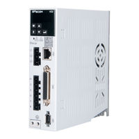
Wecon VD2 SA Series Manual (330 pages)
Brand:
Wecon
| Category:
Servo Drives
| Size: 10 MB
Table of Contents
Table of Contents
6
Safety
8
Safety Precautions
8
Wiring
8
Panel
8
Precautions For Storage And Transportation
9
Precautions During Installation
9
Communication
9
Precautions During Wiring
10
Precautions During Operation
10
Precautions During Maintenance And Inspection
11
Product Information
12
Servo Drives
12
Installation of Servo Drive and Motor
15
Operation
16
Parameters
17
Servo Motors
22
Mounting Hole
23
Specifications of Servo Motor
24
Installation Of Servo Drive
25
Dimensions (Unit: MM)
25
Installation Site
27
Installation Environment
27
Installation Of Servo Motor
33
Installation Precautions
37
Main Circuit Wiring
38
Main Circuit Terminals
38
Power Wiring
44
Power Cable Connection Of Servo Drive And Servo Motor
49
Encoder Cable Connection Of Servo Drive And Servo Motor
50
Servo Drive Control Input And Output Wiring
55
Analog Input Signal
64
Brake Wiring
72
Communication Signal Wiring
74
Malfunctions
74
Panel Composition
78
Panel Display
78
Display Switching
79
Status Display
79
Parameter Display
79
Fault Display
81
Monitor Display
82
Panel Operation
83
Parameter Setting
83
Jog Operation
84
Factory Reset
85
Basic Settings
86
Adjustments
86
Check before Operation
86
Rotation Direction Selection
87
Braking Resistor
87
Position Control Mode
97
Appendix
106
Electronic Gear Ratio
108
Speed Control Mode
117
Torque Control Mode
127
Mixed Control Mode
133
Absolute System
134
Other Functions
140
Motor Overload Protection
143
Homing Mode (Hm)
144
Control Block Diagram
144
Introduction to Homing Mode
145
Overview
186
Inertia Recognition
187
Gain Adjustment
189
Manual Gain Adjustment
191
Gain Switching
196
Mechanical Resonance Suppression
204
Notch Filter
204
Low Frequency Vibration Suppression
206
Modbus Communication
209
Hardware Wiring
209
Modbus Communication Protocol Analysis
210
Error Response Frame
211
Communication Example
211
Servo Communication Parameter Setting
213
Modbus Communication Variable Address And Value
215
Group P00 Basic Settings
217
Group P01 Control Parameters
222
Group P02 Gain Adjustment
228
Group P03 Self-Adjusting Parameters
234
Group P04 Vibration Suppression
236
Group P05 Signal Input And Output
240
Group P06 DI/Do Configuration
244
Group P07 Multi-Segment Position
247
Group P10 Accessibility
255
Group P12 Communication Parameters
258
Group P13 Communication Input And Output Terminal
259
Group U0 Universal Monitoring
262
Group U1 Warning Monitoring
269
Group U2 Device Monitoring
272
Faults And Warnings Handling At Startup
274
Faults And Warnings Handling During Operation
278
Troubleshooting
282
Lists Of Parameters
306
List Of Fault And Warning Codes
327
Wire
328
Advertisement
Wecon VD2 SA Series User Manual (171 pages)
Brand:
Wecon
| Category:
Servo Drives
| Size: 10 MB
Table of Contents
Table of Contents
4
Chapter 1 Safety Reminder
8
Safety Precautions
8
Precautions for Storage and Transportation
9
Precautions During Installation
9
Precautions During Wiring
10
Precautions During Operation
10
Precautions During Maintenance and Inspection
11
Chapter 2 Product Information
12
Servo Drive Products
12
Servo Drive Model Naming
12
The Composition of the Servo Drives
13
Electrical Specifications of the Servo Drive
14
Servo Motor Products
15
Servo Motor Model Naming
15
Composition of Servo Motor
15
Electrical Specifications of the Servo Motor
16
Chapter 3 Installation of Servo Drive and Motor
17
Installation of Servo Drive
17
Dimensions (Unit: MM)
17
Installation Site
17
Installation Environment
18
Installation Matters
18
Installation of Servo Motor
20
Dimensions (Unit: MM)
20
Installation Site
23
Installation Environment
23
Installation Precautions
23
Chapter 4 Wiring
25
Main Circuit Wiring
25
Main Circuit Terminals
25
Power Wiring Example
27
Precautions for Main Circuit Wiring
29
Power Line Connection of Servo Driver and Servo Motor
30
Power Cable
30
Brake Device Cable
30
Encoder Cable Connection of Servo Drive and Servo Motor
31
Drive Input and Output Control Terminal CN2 Connection
34
CN2 Pin Distribution Diagram
34
Wiring Diagram of each Pulse Mode
35
Position Instruction Input Signal
36
Analog Input Signal
37
Digital Input and Output Signals
37
Communication Signal Wiring
40
Communication Signal Connector
40
Host Computer Communication Connection
41
PLC Communication Connection
42
Chapter 5 Panel
43
Panel Composition
43
Panel Display
44
Display Switching
44
Status Display
45
Parameter Display
45
Fault Display
47
Monitor Display
47
Panel Operation
48
Parameter Setting
48
Jog Operation
49
Restore Factory Settings
50
Chapter 6 Operation
52
Basic Settings
52
Check before Operation
52
Power on
52
Jog Operation
52
Rotation Direction Selection
53
Braking Resistor
53
Servo Operation
54
Servo Shutdown
55
Brake Device
58
Position Control Mode
62
Position Instruction Input Setting
63
Electronic Gear Ratio
73
Position Instruction Filtering
75
Clearance of Position Deviation
76
Position-Related DO Output Function
76
Speed Control Mode
78
Speed Instruction Input Setting
79
Acceleration and Deceleration Time Setting
81
Speed Instruction Limit
82
Zero-Speed Clamp Function
82
Speed-Related DO Output Function
83
Torque Control Mode
87
Torque Instruction Input Setting
88
Torque Instruction Filter
88
Torque Instruction Limit
89
Torque DO Output Functions
90
Mixed Control Mode
91
Absolute Value System
92
Overview
92
Single-Turn Absolute Value System
92
Multi-Turn Absolute Value System
93
Encoder Feedback Data
94
Precautions for the Use of the Battery Box of the Absolute Value System Encoder
94
Chapter 7 Adjustments
96
Overview
96
Inertia Recognition
97
Gain Adjustment
98
Automatic Gain Adjustment
98
Manual Gain Adjustment
100
Feedforward Gain
102
Mechanical Resonance Suppression
103
Mechanical Resonance Suppression Methods
103
Notch Filter
103
Chapter 8 Communication
106
Modbus Communication
106
Hardware Wiring
106
Modbus Communication Protocol Analysis
107
Modbus Data Frame Format
107
Description of Supported Function Codes
107
CRC Check
108
Error Response Frame
109
Communication Example
109
Servo Communication Parameter Setting
110
Modbus Communication Variable Address and Value Description
111
Variable Address Description
111
Variable Value Type Description
112
Numerical Unit Description
112
Chapter 9 Parameters
113
Basic Settings
113
Control Setting
116
Gain Adjustment
120
Self-Adjusting Parameters
121
Vibration Suppression
122
Signal Input and Output
123
DI/DO Configuration
126
Multi-Position
137
Accessibility
143
Communication Parameters
145
Virtual Input Terminal
145
Monitoring Parameters
146
Chapter 10 Malfunctions
149
Handling of Faults and Warnings at Startup
149
Position Control Mode
149
Speed Control Mode
150
Torque Control Mode
151
Handling of Faults and Warnings During Operation
152
Overview
152
Fault and Warning Code Table
153
Chapter 11 Modbus Register Address
161
Basic Settings
161
Control Settings
162
Gain Parameters
163
Self-Tuning Parameters
163
Vibration Suppression
163
Signal Input and Output
164
DIDO Configuration
164
Multi-Position
165
Accessibility
168
Communication Parameters
168
Virtual Input Terminal
168
Monitoring Parameters
169
Wecon VD2 SA Series Manual (133 pages)
Brand:
Wecon
| Category:
Servo Drives
| Size: 8 MB
Advertisement
Advertisement
Related Products
Wecon VD2-010SA1G
Wecon VD2-014SA1G
Wecon VD2-016SA1G
Wecon VD2-019SA1G
Wecon VD2-021SA1G
Wecon VD2-025SA1G
Wecon VD2-030SA1G
Wecon VD2F-003SA1P
Wecon VD2F-010SA1P
Wecon VD2F-014SA1P
Wecon Categories
Control Unit
Controller
Touch Panel
Control Panel
Inverter
More Wecon Manuals
Login
Sign In
OR
Sign in with Facebook
Sign in with Google
Upload manual
Upload from disk
Upload from URL