
Related Manuals for Wecon VD2 SA Series


Summary of Contents for Wecon VD2 SA Series
- Page 1 Wecon VD2 SA Series Servo Drives Manual (Lite V1.1) Wecon VD2 SA Series Servo Drives Manual (Lite V1.1) Website: http://www.we-con.com.cn/en Phone:86-591-8786886 Date: September 24, 2022 WECON technology Co., Ltd...
- Page 2 Wecon VD2 SA Series Servo Drives Manual (Lite V1.1) Preface This manual is applicable to Wecon VD2 Series absolute value servo drives (VD2 SA series). In order to use this series of servo drives correctly, please read this manual carefully in advance and save it for later use.
- Page 3 Wecon VD2 SA Series Servo Drives Manual (Lite V1.1) User manual change record The following table lists the servo driver models and supported firmware. Supported Supported models Corresponding model firmware VD2-010SA1G VD2A VD2-014SA1G V1.10 V1.12 VD2-016SA1G V1.13 VD2-019SA1G VD2B Wecon VD2SA...
- Page 4 Wecon VD2 SA Series Servo Drives Manual (Lite V1.1) Contents 1.1 Safety precautions ........................1 1. Safety reminder .........................1 1.2 Precautions for storage and transportation ................2 1.3 Precautions during installation ....................2 1.4 Precautions during wiring ......................3 1.5 Precautions during operation ....................3 1.6 Precautions during maintenance and inspection ..............4...
- Page 5 Wecon VD2 SA Series Servo Drives Manual (Lite V1.1) 5.1 Panel composition ........................50 5. Panel ............................50 5.2 Panel display ..........................50 5.2.1 Display switching ......................51 5.2.2 Status display ........................51 5.2.3 Parameter display ......................51 5.2.4 Fault display ........................53 5.2.5 Monitor display .........................
- Page 6 Wecon VD2 SA Series Servo Drives Manual (Lite V1.1) Group U1 Warning monitoring ....................126 Group U2 Device monitoring ....................127 WECON technology Co., Ltd...
- Page 7 Wecon VD2 SA Series Servo Drives Manual (Lite V1.1) 1. Safety reminder 1.1 Safety precautions This section describes the important items that users must observe, such as product confirmation, storage, transportation, installation, wiring, operation, inspection, and dispoal. Please follow the steps required by this manual for trial operation.
- Page 8 Wecon VD2 SA Series Servo Drives Manual (Lite V1.1) 1.2 Precautions for storage and transportation Please keep and install in the following environment: ✎Places without direct sunlight; ✎Places where the ambient temperature does not exceed product specifications; ✎Places where the relative humidity does not exceed product specifications;...
- Page 9 Wecon VD2 SA Series Servo Drives Manual (Lite V1.1) 1.4 Precautions during wiring ✎Do not connect the three-phase power supply to the output terminals U, V, W of the servo drive, otherwise it may damage the device or cause a fire;...
- Page 10 Wecon VD2 SA Series Servo Drives Manual (Lite V1.1) ✎When an alarm occurs, reset the alarm after removing the cause and ensuring safety, and restart the operation, otherwise it may cause injury. ✎Except for special purposes, do not change the maximum speed value (P1-10). If you change it carelessly, it may damage the machine or cause injury.
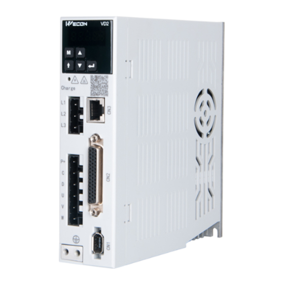
- Page 11 Wecon VD2 SA Series Servo Drives Manual (Lite V1.1) 2. Product Information 2.1 Servo drives 2.1.1 Servo drive model naming Figure 2-1 Servo drive model Figure 2-2 (VD2A) and Figure 2-3 (VD2B) show the exterior and nameplate of the VD2 series absolute value servo drive.
- Page 12 Wecon VD2 SA Series Servo Drives Manual (Lite V1.1) WECON Technology Co.,Ltd. Servo model Model: VD2-019SA1G Rated input Input: 1PH/3PH AC 200~240V 50/60Hz Rated output Output: 3PH AC 0~240V 0~400Hz 19A V1.0.0 Manufacture number D141312008281XXXXXXX MADE IN CHINA WARNING Please operate according to the manual Danger and connect PE well in case of accident.
- Page 13 Wecon VD2 SA Series Servo Drives Manual (Lite V1.1) 2.1.2 The composition of servo drive C 6: RS485 communication port C 5: RS485 communication port Operation panel High voltage indicator Power input connector Power input Motor output connector Braking resistor...
- Page 14 Wecon VD2 SA Series Servo Drives Manual (Lite V1.1) The 220V power supply specifications and 380V power supply specifications of the VD2B drive have the same appearance and composition. C 4: Host com puter RS422 com m unica on port or RS485 com m unica on port...
- Page 15 Wecon VD2 SA Series Servo Drives Manual (Lite V1.1) 2.1.3 Specification of servo drive Electrical specifications Item VD2A VD2B Model VD2-010SA1G VD2-014SA1G VD2-016SA1G VD2-019SA1G Maximum output current Control power Single-phase AC 198 to 242V supply 50/60Hz Power supply Single-phase AC 198 to 242V, 50/60Hz...
- Page 16 Wecon VD2 SA Series Servo Drives Manual (Lite V1.1) 2.2 Servo motors 2.2.1 Servo motor model naming Figure 2-9 Servo motor naming N a m e p la te AC SERVO MOTOR M o d e l W D 80M -07530S-D 2G Pn: 0.75KW...
- Page 17 Wecon VD2 SA Series Servo Drives Manual (Lite V1.1) Encoder socket Motor power cable socket Flange Encoder Motor shaft Motor housing Figure 2-12 Motor composition of 110 and 130 flange 2.2.3 Specification of servo motor Rated Rated Rated Motor Voltage...
- Page 18 Wecon VD2 SA Series Servo Drives Manual (Lite V1.1) 3. Installation of servo drive and motor 3.1 Installation of servo drive 3.1.1 Dimensions (Unit: mm) Figure 3-1 Installation dimensions of VD2A servo drive Figure 3-2 Installation dimensions of VD2B servo drive...
- Page 19 Wecon VD2 SA Series Servo Drives Manual (Lite V1.1) Figure 3-3 Installation dimensions of VD2F servo drive 3.1.2 Installation site Please install it in an installation cabinet free from sunlight and rain; In a place without vibration; Please do not install in the environment of high temperature, humidity, dust and metal dust;...
- Page 20 Wecon VD2 SA Series Servo Drives Manual (Lite V1.1) 3.1.4 Installation matters (1) Installation specifications In order to achieve a good cooling cycle effect, ensure that there is enough ventilation space around it when installing the servo drive, and be sure to comply with the installation standards in the control cabinet shown in the figure below, otherwise it may cause the drive to malfunction.
- Page 21 Wecon VD2 SA Series Servo Drives Manual (Lite V1.1) Figure 3-5 Parallel installation dimensions of multiple VD2A drives WECON technology Co., Ltd Figure 3-6 Parallel installation dimensions of multiple VD2B drives...
- Page 22 Wecon VD2 SA Series Servo Drives Manual (Lite V1.1) >100mm >100mm >100mm >40mm >40mm >20mm >20mm Charge Charge Charge >100mm >100mm >100mm Figure 3-7 Parallel installation dimensions of multiple VD2F drives (3) Installation direction When installing the servo drive, please face the front of the servo drive (panel control interface) to the operator so that the servo drive is perpendicular to the wall.
- Page 23 Wecon VD2 SA Series Servo Drives Manual (Lite V1.1) 3.2 Installation of servo motor 3.2.1 Installation dimensions (unit: mm) (1) Installation dimensions of WD series 40 flange servo motor Specification WD series 40 flange motor Rated torque (N.m) 0.318 LA without brake (mm) 74.8...
- Page 24 Wecon VD2 SA Series Servo Drives Manual (Lite V1.1) (3) Installation dimensions of 80 flange servo motor 1) WD series motor Specification WD series 80 flange motor Rated torque (N.m) 2.39 LA without brake (mm) 98.5 LA with brake (mm) 132.5...
- Page 25 Wecon VD2 SA Series Servo Drives Manual (Lite V1.1) (4) Installation dimensions of WE series 110 flange servo motor Specification WE series 110 flange motor Rated torque (N.m) LA without brake (mm) LA with brake (mm) M6 L25 × 4- 9 15.5...
- Page 26 Wecon VD2 SA Series Servo Drives Manual (Lite V1.1) 3.2.2 Installation site Do not use the motor near corrosive, flammable gas environment, combustible materials such as hydrogen sulfide, chlorine, ammonia, sulfur, chlorinated gas, acid, alkali, salt, etc. Do not remove the oil seal in places where there is grinding fluid, oil mist, iron powder, cutting, etc.
- Page 27 Wecon VD2 SA Series Servo Drives Manual (Lite V1.1) ✎When using, please make sure the oil level is lower than the lip of the oil seal; ✎The oil seal can be used in a state with a good degree of splashing of oil foam;...
- Page 28 Wecon VD2 SA Series Servo Drives Manual (Lite V1.1) 4. Wiring 4.1 Main circuit wiring 4.1.1 Main circuit terminals (1) VD2A servo drive main circuit terminal distribution Figure 4-1 VD2A servo drive main circuit terminal distribution Terminal Terminal name Terminal function...
- Page 29 Wecon VD2 SA Series Servo Drives Manual (Lite V1.1) (2) VD2B servo drive main circuit terminal distribution Figure 4-2 VD2B servo drive main circuit terminal distribution Terminal Terminal name Terminal function number Power input Three-phase 220V AC input is connected to L1, L2, L3;...
- Page 30 Wecon VD2 SA Series Servo Drives Manual (Lite V1.1) (3) VD2F servo drive main circuit terminal distribution Charge Figure 4-3 VD2F servo drive main circuit terminal distribution Terminal Terminal name Terminal function number Power input Connect single-phase 220V input power terminal Use internal braking resistor: short-circuit C and D.
- Page 31 Wecon VD2 SA Series Servo Drives Manual (Lite V1.1) 4.1.2 Power wiring (1) VD2SA drive single-phase 220V main circuit wiring Figure 4-4 VD2A drive single-phase 220V main circuit wiring WECON technology Co., Ltd...
- Page 32 Wecon VD2 SA Series Servo Drives Manual (Lite V1.1) (2) VD2B drive single-phase 220V main circuit wiring External brake resistor Internal temperature control switch Inductive surge absorber M CCB (Single-phase) Power input AC220V,50Hz Incoming line reactor O 1C N o ise filte r...
- Page 33 Wecon VD2 SA Series Servo Drives Manual (Lite V1.1) (3) VD2B drive three-phase 220V main circuit wiring External brake resistor Internal temperature control switch Inductive surge absorber M CCB (Three-phase) Power input AC220V,50Hz Incoming line reactor N o ise filte r...
- Page 34 Wecon VD2 SA Series Servo Drives Manual (Lite V1.1) (4) VD2F drive single-phase 220V main circuit wiring External brake resistor Internal temperature control switch Inductive surge absorber MCCB Power Power input (Single-phase) AC220V 50Hz Incoming line reactor External brake resistor...
- Page 35 4.2 Power line connection of servo drive and servo motor 4.2.1 Power line Wecon VD2 series servo drives have 3 kinds of interface power cables: rectangular plug, aviation plug and in-line type. Motor...
- Page 36 Wecon VD2 SA Series Servo Drives Manual (Lite V1.1) 4.2.2 Brake device cable Connector exterior terminal pin distribution Motor flange Pin number Signal name WD series Pin number Signal name DC 24V WE series Table 4-5 Brake device cable 4.3 Encoder cable connection of servo drive and servo motor...
- Page 37 Wecon VD2 SA Series Servo Drives Manual (Lite V1.1) View from here View from here Pin number Signal name Shield Battery+ Battery- Table 4-7 Absolute value encoder line connector (Rectangular plug) Drive side J1394 Motor side Description Rectangular plug Pin number...
- Page 38 Wecon VD2 SA Series Servo Drives Manual (Lite V1.1) Pin number Signal name Shield Battery+ Battery- Table 4-9 Absolute value encoder line connector (Aviation plug) Drive side J1394 Motor side Description Aviation plug Pin number Signal name Cable color pin number...
- Page 39 Wecon VD2 SA Series Servo Drives Manual (Lite V1.1) Pin number Signal name Shield Battery+ Battery- Table 4-11 Absolute encoder cable connector (in-line type) Drive side J1394 Motor side Description In-line plug Pin number Signal name Cable color pin number...
- Page 40 Wecon VD2 SA Series Servo Drives Manual (Lite V1.1) 4.4 Servo drive control input and output wiring 4.4.1 CN2 pin distribution (1) VD2A and VD2B servo drive control input and output pin distribution (CN2 interface) Figure 4-9 VD2A and VD2B servo drive control input and output pin distribution...
- Page 41 Wecon VD2 SA Series Servo Drives Manual (Lite V1.1) (2) VD2F servo drive control input and output pin distribution (CN2 interface) Figure 4-10 VD2F servo drive control input and output pin distribution Pin number Signal name Pin number Signal name...
- Page 42 Wecon VD2 SA Series Servo Drives Manual (Lite V1.1) 4.4.2 Wiring diagram of each mode (1) VD2A and VD2B servo drive Analog torque mode wiring Analog torque mode wiring Analog speed mode wiring AI_1+ AI_1+ Analog torque Analog torque AI_1-...
- Page 43 Wecon VD2 SA Series Servo Drives Manual (Lite V1.1) (2) VD2F servo drive Position pulse mode wiring External +24V 2.2k 2.2k 100R PULS+ Pulse input 100R P LS- 2.2k 2.2k 100R SIGN+ Direction input 100R SIGN- External +24V DOCOM Ground terminal is connected...
- Page 44 Wecon VD2 SA Series Servo Drives Manual (Lite V1.1) 4.4.3 Position instruction input signal Signal VD2A and VD2B VD2F pin Function name pin number number Low-speed pulse input modes: differential input, open PULS+ collector. There are three types of input pulse:...
- Page 45 Wecon VD2 SA Series Servo Drives Manual (Lite V1.1) Figure 4-14 VD2F servo drive differential input connection (2) Open collector input 1) Open collector input connection Figure 4-15 VD2A and VD2B servo drive open collector input connection Figure 4-16 VD2F servo drive open collector input connection...
- Page 46 Wecon VD2 SA Series Servo Drives Manual (Lite V1.1) 2) NPN and PNP wiring Figure 4-17 Triode Wiring 4.4.4 Analog input signal The analog input signal is only supported by VD2A and VD2B servo drives. Pin number Signal name Function AI_1+ AI_1 analog input signal, resolution 12-bit.
- Page 47 Wecon VD2 SA Series Servo Drives Manual (Lite V1.1) 4.4.5 Digital input and output signals (1) VD2A and VD2B servo drives Pin number Signal name Default function Servo enable Fault and alarm clearance Forward drive prohibited Reverse drive prohibited Inverted instruction...
- Page 48 Wecon VD2 SA Series Servo Drives Manual (Lite V1.1) When the control device (HMI/PLC) is open collector output Figure 4-20 Open collector output 2) Digital output circuit When the control device(HMI/PLC) is relay input Figure 4-21 Relay input WECON technology Co., Ltd...
- Page 49 Wecon VD2 SA Series Servo Drives Manual (Lite V1.1) When the control device (HMI/PLC) is optocoupler input Figure 4-22 Optocoupler input (2) VD2F servo drive Pin number Pin name Default function Servo enable Fault and alarm clearance Forward drive prohibited...
- Page 50 Wecon VD2 SA Series Servo Drives Manual (Lite V1.1) 1) Digital input circuit When the control device (HMI/PLC) is relay output Figure 4-23 Relay output When the control device (HMI/PLC) is open collector output Figure 4-24 Open collector output WECON technology Co., Ltd...
- Page 51 Wecon VD2 SA Series Servo Drives Manual (Lite V1.1) 2) Digital output circuit When the control device (HMI/PLC) is relay input Figure 4-25 Relay output When the control device (HMI/PLC) is optocoupler input Figure 4-26 Optocoupler input WECON technology Co., Ltd...
- Page 52 Figure 4-28 Brake wiring of VD2F 4.5 Communication signal wiring Wecon VD2 series servo drive supports two communication modes: RS-422 and RS-485. The communication port is RJ45 socket. The exterior of communication terminal is shown in Figure 4-29. WECON technology Co., Ltd...
- Page 53 Wecon VD2 SA Series Servo Drives Manual (Lite V1.1) Figure 4-29 Pin number of an RJ45 socket The communication modes supported by the driver communication ports are in the following table. VD2 A&VD2 B VD2F Port Communication mode Port Communication mode...
- Page 54 Wecon VD2 SA Series Servo Drives Manual (Lite V1.1) Please prepare the cables by yourselves → RS422 Host PC and upper controller Figure 4-31 The connection between VD2B drive and PC Name Function description Computer sends negative terminal (drive receives negative)
- Page 55 Wecon VD2 SA Series Servo Drives Manual (Lite V1.1) CN3&CN4 Name Function description Computer sends negative terminal (drive receives negative) Computer sends positive terminal (drive receives positive) Computer receives negative terminal (drive sends negative) Ground terminal Not used Computer receives positive terminal (drive sends positive)
- Page 56 Wecon VD2 SA Series Servo Drives Manual (Lite V1.1) 5. Panel 5.1 Panel composition The panel composition of the VD2 series servo drive is shown in Figure 5-1.(take VD2A servo drive as an example). LOGO Panel display Key function Figure 5-1 The exterior of VD2 A servo drive panel...
- Page 57 Wecon VD2 SA Series Servo Drives Manual (Lite V1.1) 5.2.1 Display switching Figure 5-2 Switch between display types on the panel Illustrate: The power is turned on, and the panel display of the servo drive enters “Status Display Mode”. After an operation failure occurs, the panel immediately switches to the bit failure display mode.
- Page 58 Wecon VD2 SA Series Servo Drives Manual (Lite V1.1) The parameter display is the display of different function codes. The format of the function code is “PXX.YY”. “PXX” indicates the group number of function code, and “YY” indicates the number within the function code group.
- Page 59 Wecon VD2 SA Series Servo Drives Manual (Lite V1.1) (4) Parameter setting display Display Name Display occasion Meaning Done The servo drive is in the Parameter setting Parameter reset factory process of parameter completed factory reset P.Init The servo drive is in the...
- Page 60 Wecon VD2 SA Series Servo Drives Manual (Lite V1.1) 5.2.5 Monitor display After the servo drive is powered on or the servo enable is ON, you can press the "Mode" key to enter the monitor display mode. Monitoring Display Name...
- Page 61 Wecon VD2 SA Series Servo Drives Manual (Lite V1.1) 5.3 Panel operation 5.3.1 Parameter setting Use the servo drive panel to set the parameters. For details about the parameters, please refer to " Parameters". Take P00.01 as an example to set the parameters to change the control mode of the servo drive from position control mode to speed control mode.
- Page 62 Wecon VD2 SA Series Servo Drives Manual (Lite V1.1) 5.3.2 Jog operation In order to test run the servo motor and the servo drive, you can use the jog running function. The operation steps are shown in Figure 5-6. Illustrate: Adjust the function code to P10.01 after power on.
- Page 63 Wecon VD2 SA Series Servo Drives Manual (Lite V1.1) 5.3.3 Factory reset The factory settings can be restored through the servo drive panel. The specific operation steps are shown in Figure 5-7. Illustrate: After power on, modify the function code to P10.02.
- Page 64 Wecon VD2 SA Series Servo Drives Manual (Lite V1.1) 6. Parameters Group P00 Basic settings Parameter name Setting method Effective time Default Range Category Unit P00-01 Shutdown Effective Control mode 1 to 6 Basic setting setting immediately Used to set the control mode of servo drive...
- Page 65 Wecon VD2 SA Series Servo Drives Manual (Lite V1.1) Parameter name Setting method Effective time Default Range Category Unit P00-05 Servo OFF shutdown Shutdown Effective 0 to 1 Basic setting method setting immediately Set the forward rotation direction of the motor when looking at the motor axis.
- Page 66 Wecon VD2 SA Series Servo Drives Manual (Lite V1.1) Parameter name Setting method Effective time Default Range Category Unit P00-13 Maximum position Shutdown Effective Position 1 to 500 pulse frequency setting immediately mode In position control mode, when position instruction source is pulse instruction (P01-06=0) , input the maximum frequency of pulse.
- Page 67 Wecon VD2 SA Series Servo Drives Manual (Lite V1.1) Parameter name Setting method Effective time Default Range Category Unit P00-22 The number of output Operation Power-on 0 to Position 2500 ☆ pulses per turn of motor setting again 2500 mode ✎Note: Each rotation of the motor, phase A and phase B can each output up to 2500 pulses, and the control...
- Page 68 Wecon VD2 SA Series Servo Drives Manual (Lite V1.1) Group P01 Control parameters Parameter name Setting method Effective time Default Range Category Unit P01-01 Speed instruction Shutdown setting Power-on again 0 to 1 Speed mode source Select speed instruction source...
- Page 69 Wecon VD2 SA Series Servo Drives Manual (Lite V1.1) Parameter name Setting method Effective time Default Range Category Unit P01-08 Torque instruction Operation Effective -3000 to 0.1% keyboard setting value setting immediately 3000 Used to set the required torque instruction value when P01-07 is set to 0 (internal torque instruction).
- Page 70 Wecon VD2 SA Series Servo Drives Manual (Lite V1.1) performing acceleration and deceleration movements. Please refer to full version manual V1.1 “6.4.3 Torque instruction limit”. Parameter name Setting method Effective time Default Range Category Unit P01-17 Forward speed limit Operation...
- Page 71 Wecon VD2 SA Series Servo Drives Manual (Lite V1.1) Parameter name Setting method Effective time Default Range Category Unit P01-24 -3000 to 3000 Internal speed Operation Effective Speed Instruction 2 setting immediately mode -5000 to 5000* Used to set the speed value of internal speed instruction 2. “*” indicates the setting range of VD2F servo drive.
- Page 72 Wecon VD2 SA Series Servo Drives Manual (Lite V1.1) Parameter name Setting method Effective time Default Range Category Unit Rotation status, delay from P01-33 Operation 1 to servo enable OFF to brake setting 1000 output OFF The motor is rotating, the delay time from the brake (BRK-OFF) output OFF is allowed to the servo enable (S-ON) OFF.
- Page 73 Wecon VD2 SA Series Servo Drives Manual (Lite V1.1) Parameter name Setting method Effective time Default Range Category Unit P02-10 Speed feedforward Operation 0 to Gain Effective 0.1ms filtering time constant setting immediately 10000 control Set the time constant of one delay filter related to the speed feedforward input.
- Page 74 Wecon VD2 SA Series Servo Drives Manual (Lite V1.1) Parameter name Setting method Effective time Default Range Category Unit Automatic P03-05 Number of circles Shutdown Effective 1 to 20 parameter Circle Inertia recognition setting immediately tuning Offline load inertia recognition process, motor rotation number setting...
- Page 75 Wecon VD2 SA Series Servo Drives Manual (Lite V1.1) The position instruction is trapezoidal wave Parameter name Setting method Effective time Default Range Category Unit Position instruction P04-03 Shutdown Position Effective average filtering time 0 to 128 setting immediately mode constant Used to set average filtering time constant.
- Page 76 Wecon VD2 SA Series Servo Drives Manual (Lite V1.1) Parameter name Setting method Effective time Default Range Category Unit P04-07 1st notch filter Operation Effective Vibration 0 to 12 width setting immediately suppression Set the notch filter width grade (the ratio between input and output at the center frequency of the notch filter)
- Page 77 Wecon VD2 SA Series Servo Drives Manual (Lite V1.1) Parameter name Setting method Effective time Default Range Category Unit P05-04 Operation Effective Analog AI_1 zero drift -500 to 500 ☆ setting immediately input Set the zero drift of AI_1 channel analog. “zero drift” is the sample voltage co voltage relative to GND when analog channel voltage is 0.
- Page 78 Wecon VD2 SA Series Servo Drives Manual (Lite V1.1) Set the speed value corresponding to the analog 10V Mode Function code value Sampling voltage and speed diagram Speed mode P01-01=1 Given speed = sampling voltage / 10 * (P05-09) Parameter name...
- Page 79 Wecon VD2 SA Series Servo Drives Manual (Lite V1.1) Parameter name Setting method Effective time Default Range Category Unit Positioning P05-12 Operation Effective 1 to Position Equivalent completion setting immediately 65535 mode pulse unit threshold Set the threshold of absolute value of position deviation when servo drive output positioning completion signal...
- Page 80 Wecon VD2 SA Series Servo Drives Manual (Lite V1.1) Parameter name Setting method Effective time Default Range Category Unit P05-21 Torque arrival Operation Effective Torque 0 to 20 hysteresis value setting immediately mode Please refer to full version manual 6.4.5 Torque-related DO output functions.
- Page 81 Wecon VD2 SA Series Servo Drives Manual (Lite V1.1) Parameter name Setting method Effective time Default Range Category Unit P06-04 DI_1 input Operation setting Effective immediately 0 to 1 DI/DO source selection Select the enabled DI_1 port type Set value...
- Page 82 Wecon VD2 SA Series Servo Drives Manual (Lite V1.1) Parameter name Setting method Effective time Default Range Category Unit P06-16 DI_5 input Operation setting Effective immediately 0 to 1 DI/DO ☆ source selection Parameter name Setting method Effective time Default...
- Page 83 Wecon VD2 SA Series Servo Drives Manual (Lite V1.1) Parameter name Setting method Effective time Default Range Category Unit P06-26 DO_1 channel Operation Effective 128 to 142 DI/DO function selection setting immediately Set DO functions corresponding to hardware DO_1. The related functions are as below.
- Page 84 Wecon VD2 SA Series Servo Drives Manual (Lite V1.1) Group P07 multi-segment position Effective Parameter name Setting method Default Range Category Unit time P07-01 Multi-segment position Shutdown Effective 0 to 2 operation mode setting immediately When servo is in position mode, and P01-06 (position instruction source) =1, set the operation mode of...
- Page 85 Wecon VD2 SA Series Servo Drives Manual (Lite V1.1) Parameter Setting method Effective time Default Range Category Unit name P07-04 Margin handling Shutdown Effective 0 to 1 method setting immediately The starting segment number used for the servo drive will run when it resumes after pausing in multi-segment.
- Page 86 Wecon VD2 SA Series Servo Drives Manual (Lite V1.1) Setting Effective Parameter name Default Range Category Unit method time P07-11 Acceleration and Operation Effective deceleration time of the 1 to 65535 setting immediately 1st segment displacement Used to set the time when the motor in the multi-segment position is uniformly accelerated from 0rpm to the P07-10 (maximum speed of the 1st segment displacement) in the multi-segment position.
- Page 87 Wecon VD2 SA Series Servo Drives Manual (Lite V1.1) Setting Effective Parameter name Default Range Category Unit method time P07-21 The 4th segment Operation Effective -2147483647 to 10000 displacement setting immediately 2147483646 Setting Effective Parameter name Default Range Category Unit...
- Page 88 Wecon VD2 SA Series Servo Drives Manual (Lite V1.1) Parameter name Setting method Effective time Default Range Category Unit Waiting time after P07-32 Operation Effective 1 to Set by completion of the 6th setting immediately 65535 P07-06 segment displacement Setting...
- Page 89 Wecon VD2 SA Series Servo Drives Manual (Lite V1.1) Setting Effective Parameter name Default Range Category Unit method time P07-43 Acceleration and Operation Effective deceleration time of the 1 to 65535 setting immediately 9th segment displacement Parameter name Setting method...
- Page 90 Wecon VD2 SA Series Servo Drives Manual (Lite V1.1) Setting Effective Parameter name Default Range Category Unit method time P07-54 Maximum speed of the 12th Operation Effective 1 to 5000 segment displacement setting immediately Setting Effective Parameter name Default Range...
- Page 91 Wecon VD2 SA Series Servo Drives Manual (Lite V1.1) Setting Effective Parameter name Default Range Category Unit method time P07-65 The 15th segment Operation Effective -2147483647 to 10000 displacement setting immediately 2147483646 Setting Effective Parameter name Default Range Category Unit...
- Page 92 Wecon VD2 SA Series Servo Drives Manual (Lite V1.1) Parameter name Setting method Effective time Default Range Category Unit P10-03 Effective Fault clearing Operation setting 0 to 1 Accessibility immediately Fault reset operation selection Set value Function Remarks No operation...
- Page 93 Wecon VD2 SA Series Servo Drives Manual (Lite V1.1) Group P12 Communication parameters Parameter name Setting method Effective time Default Range Category Unit P12-01 Operation Effective Communication Servo address 1 to 247 setting immediately parameter Set the Modbus communication address of servo drive...
- Page 94 Wecon VD2 SA Series Servo Drives Manual (Lite V1.1) Group P13 Communication input and output terminal Parameter name Setting method Effective time Default Range Category Unit P13-01 Operation Effective Virtual VDI_1 input value 0 to 1 DI/DO setting immediately When P06-04 is set to 1, DI_1 channel logic is controlled by this function code.
- Page 95 Wecon VD2 SA Series Servo Drives Manual (Lite V1.1) Parameter name Setting method Effective time Default Range Category Unit P13-12 Operation Effective Virtual VD0_2 input value 0 to 1 DI/DO setting immediately Parameter name Setting method Effective time Default Range...
- Page 96 Take the DI1 to DI7 terminals as the high level and DI8 as the low level as an example. The corresponding binary code is "01111111", and Wecon servo control device debugging software U0-17 displays the current binary value is 0b0111 1111. The panel of servo drive is displayed as below.
- Page 97 Take the DO1, DO2 and DO3 terminals as the high level and DO2 as the low level as an example. The corresponding binary code is "1101", and Wecon servo upper computer debugging software U0-17 displays the current binary value is 0b0000 1101. The panel of servo drive is displayed as below.
- Page 98 Wecon VD2 SA Series Servo Drives Manual (Lite V1.1) Monitoring name Range Category Panel display Unit Data type U0-26 Reverse torque limit value 0 to 300 Universal Decimal 16-bit Display the set value of P01-16 (reverse torque limit) of servo drive. If U0-26 is 300%, the panel of servo drive is displayed as below.
- Page 99 Wecon VD2 SA Series Servo Drives Manual (Lite V1.1) Monitoring name Range Category Panel display Unit Data type U0-35 Total operation time (hour) Universal Decimal 16-bit Monitoring name Range Category Panel display Unit Data type U0-37 Total operation time (minutes)
- Page 100 Wecon VD2 SA Series Servo Drives Manual (Lite V1.1) Monitoring name Range Category Panel display Unit Data type U0-55 Circle numbers of 0 to 65535 Universal Decimal Encoder unit 16-bit absolute encoder Display the circle number of multi-turn absolute encoder...
- Page 101 Wecon VD2 SA Series Servo Drives Manual (Lite V1.1) Monitoring name Range Category Panel display Unit Data type U1-10 The speed when faults occur Warning Decimal 16-bit Monitoring name Range Category Panel display Unit Data type U1-11 The time when faults occur...
- Page 102 Wecon VD2 SA Series Servo Drives Manual (Lite V1.1) Group U2 Device monitoring Monitoring name Range Category Panel display Unit Data type U2-01 Product series Device Hexadecimal 16-bit Display the product series code of servo drive. The product series code of VD2A and VD2B is 0x4432. The product series code of VD2F is 0x3246.
- Page 103 Wecon VD2 SA Series Servo Drives Manual (Lite V1.1) Monitoring name Range Category Panel display Unit Data type Manufacture date (year) U2-06 Device Decimal Year 16-bit Firmware date (year) * Display the year of manufacture of the VD2F drive firmware.
- Page 104 Wecon VD2 SA Series Servo Drives Manual (Lite V1.1) 7. Malfunctions 7.1 Faults and warnings handling at startup 7.1.1 Position control mode Boot process Fault phenomenon Reason Confirmation method ✎Rewiring Control terminal is ✎L1C and L2C power lines are led separately...
- Page 105 Wecon VD2 SA Series Servo Drives Manual (Lite V1.1) After troubleshooting, the servo motor should be able to rotate normally Unreasonable gain Unstable low speed Please adjust the gain. The motor does setting not rotate The motor shaft Load inertia ratio...
- Page 106 Wecon VD2 SA Series Servo Drives Manual (Lite V1.1) When the internal speed instruction is given, please confirm P01-02 (internal speed instruction )is 0. When using multi-segment speed function, please confirm the internal speed instruction parameters 0 to 7 of group P01 are right.
- Page 107 7.2 Faults and warnings handling during operation 7.2.1 Overview The faults and warnings of Wecon VD2 series servo drives are graded according to their severity, which can be divided into four grades: Category 1, Category 2, Category 3, Category 4. Severity level: Category 1>...
- Page 108 Wecon VD2 SA Series Servo Drives Manual (Lite V1.1) cleared, the servo will directly enter the Run state. When performing fault clearing actions, be sure to stop sending control instructions such as pulses to ensure personal safety. Associated function number:...
- Page 109 Wecon VD2 SA Series Servo Drives Manual (Lite V1.1) Please power on again to determine The FPGA Category The FPGA program version is whether the fault is eliminated; if program version Er.06 wrong there is still an abnormality, please is wrong contact the manufacturer.
- Page 110 Wecon VD2 SA Series Servo Drives Manual (Lite V1.1) Exceeding the maximum speed threshold of function code P1-10. Possible reasons ✎Please check whether the motor are: power line is correctly wired; ✎Wrong U/V/W phase Category Exceeds motor ✎Confirm whether the motor model sequence of motor power line Er.32...
- Page 111 Wecon VD2 SA Series Servo Drives Manual (Lite V1.1) The 2nd category (category 2 for short) clearable faults Fault Category Error name Cause of fault Troubleshooting code The drive detects that the bus voltage is too high. The possible reasons are: ✎Check whether the main power input...
- Page 112 Wecon VD2 SA Series Servo Drives Manual (Lite V1.1) ✎The braking resistor status the external braking resistor is detection circuit is abnormal. reliably connected. ✎If you use an external braking resistor, please confirm whether the resistance of the braking resistor is reasonable.
- Page 113 Wecon VD2 SA Series Servo Drives Manual (Lite V1.1) ✎Check whether the wiring of the motor power line U/V/W is The deviation of the current position normal. pulse exceeds the setting value of ✎Check the load condition of the P00-25 position deviation limit. The motor.
- Page 114 Wecon VD2 SA Series Servo Drives Manual (Lite V1.1) ✎During power failure, the multi-turn absolute value motor is Category Encoder Replace with a new encoder not connected to the battery. Er.40 battery failure battery ✎The encoder battery voltage is too low, less than 3V.
- Page 115 Wecon VD2 SA Series Servo Drives Manual (Lite V1.1) the unnecessary channels, and then power on again. Check DO channel function selection: DO_1 channel function selection (P06-26) to DI_4 channel function DO port selection (P06-32)in function code Category Different DO ports are set to...
- Page 116 Wecon VD2 SA Series Servo Drives Manual (Lite V1.1) 8. Modbus register address Group P00 Basic settings Modbus address Function Name Setting method Effective time Default Range Unit Data type code Hexadecimal Decimal P00-01 Control mode Shutdown setting Effective immediately...
- Page 117 Wecon VD2 SA Series Servo Drives Manual (Lite V1.1) Equivalent P00-25 Position deviation limit Shutdown setting Effective immediately 60000 0 to 2147483646 0x001E 32-bit pulse unit Pulse output frequency division P00-27 Operation setting Power-on again 1 to 2500 0x0021 16-bit ☆...
- Page 118 Wecon VD2 SA Series Servo Drives Manual (Lite V1.1) P01-14 Torque limit source Shutdown setting Effective immediately 0 to 1 0x010E 16-bit P01-15 Forward torque limit Operation setting Effective immediately 3000 0 to 3000 0.1% 0x010F 16-bit P01-16 Reverse torque limit...
- Page 119 Wecon VD2 SA Series Servo Drives Manual (Lite V1.1) Group P02 Gain adjustment Modbus address Function Name Setting method Effective time Default Range Unit Data type code Hexadecimal Decimal P02-01 1st position loop gain Operation setting Effective immediately 0 to 6200 0.1Hz...
- Page 120 Wecon VD2 SA Series Servo Drives Manual (Lite V1.1) P03-05 Number of cycles of inertia identification Shutdown setting Effective immediately 1 to 20 Circle 0x0305 16-bit P03-06 Maximum speed of inertia identification Shutdown setting Effective immediately 1000 300 to 2000...
- Page 121 Wecon VD2 SA Series Servo Drives Manual (Lite V1.1) Group P05 Signal input and output Modbus address Function Name Setting method Effective time Default Range Unit Data type code Hexadecimal Decimal AI_1 input bias Operation setting Effective immediately -5000 to 5000...
- Page 122 Wecon VD2 SA Series Servo Drives Manual (Lite V1.1) P05-14 Position detection window time Operation setting Effective immediately 0 to 20000 0x050E 1294 16-bit P05-15 Positioning signal hold time Operation setting Effective immediately 0 to 20000 0x050F 1295 16-bit P05-16...
- Page 123 Wecon VD2 SA Series Servo Drives Manual (Lite V1.1) P06-12 DI_4 channel logic selection Operation setting Effective immediately 0 to 1 0x060C 1548 16-bit P06-13 DI_4 input source selection Operation setting Effective immediately 0 to 1 0x060D 1549 16-bit DI_5 channel function selection...
- Page 124 Wecon VD2 SA Series Servo Drives Manual (Lite V1.1) Group P07 multi-segment position Modbus address Function Name Setting method Effective time Default Range Unit Data type code Hexadecimal Decimal P07-01 multi-segment position operation mode Shutdown setting Effective immediately 0 to 2...
- Page 125 Wecon VD2 SA Series Servo Drives Manual (Lite V1.1) -2147483647 to P07-17 The 3rd position displacement Operation setting Effective immediately 10000 0x0713 1811 32-bit 2147483646 Maximum speed of the 3rd position P07-18 Operation setting Effective immediately 1 to 5000 0x0715...
- Page 126 Wecon VD2 SA Series Servo Drives Manual (Lite V1.1) -2147483647 to P07-33 The 7th position displacement Operation setting Effective immediately 10000 0x0727 1831 32-bit 2147483646 Maximum speed of the 7th position P07-34 Operation setting Effective immediately 1 to 5000 0x0729...
- Page 127 Wecon VD2 SA Series Servo Drives Manual (Lite V1.1) -2147483647 to P07-49 The 11th position displacement Operation setting Effective immediately 10000 0x073B 1851 32-bit 2147483646 Maximum speed of the 11th position P07-50 Operation setting Effective immediately 1 to 5000 0x073D...
- Page 128 Wecon VD2 SA Series Servo Drives Manual (Lite V1.1) -2147483647 to P07-65 The 15th position displacement Operation setting Effective immediately 10000 0x074F 1871 32-bit 2147483646 Maximum speed of the 15th position P07-66 Operation setting Effective immediately 1 to 5000 0x0751...
- Page 129 Wecon VD2 SA Series Servo Drives Manual (Lite V1.1) Group P12 Communication parameters Modbus address Function Name Setting method Effective time Default Range Unit Data type code Hexadecimal Decimal P12-01 Servo address Operation setting Effective immediately 1 to 247 0x0C01...
- Page 130 Wecon VD2 SA Series Servo Drives Manual (Lite V1.1) Group U0 Monitoring parameters Modbus address Function Data Name Category Unit code type Hexadecimal Decimal U0-01 Servo Status Universal 0x1E01 7681 16-bit U0-02 Servo motor speed Universal 0x1E02 7682 16-bit U0-03...
- Page 131 Wecon VD2 SA Series Servo Drives Manual (Lite V1.1) U0-27 Forward speed limit value Universal 0x1E20 7712 16-bit U0-28 Reverse speed limit value Universal 0x1E21 7713 16-bit U0-29 Mechanical angle Universal ° 0x1E22 7714 16-bit U0-30 Electrical angle Universal °...
- Page 132 Wecon VD2 SA Series Servo Drives Manual (Lite V1.1) Group U1 Warning monitoring Modbus address Function Data Name Category Unit code type Hexadecimal Decimal U1-01 Current fault code Warning 0x1F01 7937 16-bit U1-02 Current warning code Warning 0x1F02 7938 16-bit...
- Page 133 Wecon VD2 SA Series Servo Drives Manual (Lite V1.1) Group U2 Device monitoring Modbus address Function Name Category Unit Data type code Hexadecimal Decimal U2-01 Product Series Device 0x2001 8193 16-bit U2-02 Model Device 0x2002 8194 16-bit U2-03 Model Device...
Need help?
Do you have a question about the VD2 SA Series and is the answer not in the manual?
Questions and answers