Sign In
Upload
Manuals
Brands
Walchem Manuals
Controller
W900 Series
Walchem W900 Series Manuals
Manuals and User Guides for Walchem W900 Series. We have
5
Walchem W900 Series manuals available for free PDF download: Instruction Manual, Troubleshooting Manual, Quick Programming Manual
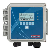
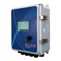
Walchem W900 Series Instruction Manual (126 pages)
Water Treatment Controller
Brand:
Walchem
| Category:
Controller
| Size: 14.89 MB
Table of Contents
Table of Contents
3
1 0 Introduction
6
2 0 Specifications
7
Measurement Performance
7
Electrical: Input/Output
8
Mechanical
10
Variables and Their Limits
11
3 0 Unpacking & Installation
14
Unpacking the Unit
14
Mounting the Electronic Enclosure
14
Sensor Installation
15
Icon Definitions
18
Electrical Installation
19
4 0 Function Overview
37
Front Panel
37
Touchscreen
37
Icons
37
Startup
39
Shut down
48
5 0 OPERATION Using the Touchscreen
48
Alarms Menu
48
Inputs Menu
49
Contacting Conductivity
52
Electrodeless Conductivity
52
Temperature
53
Orp
54
Disinfection
54
Generic Sensor
55
Corrosion Input
56
Corrosion Imbalance Input
57
Transmitter Input and AI Monitor Input
58
Fluorometer Input
58
Analog Flowmeter Input
59
DI State
59
Flow Meter, Contactor Type
60
Flow Meter, Paddlewheel Type
60
Feed Monitor
61
DI Counter Input
63
Virtual Input - Calculation
63
Virtual Input - Redundant
64
Virtual Input - Raw Value
65
Virtual Input - Disturbance
66
Outputs Menu
67
Relay, any Control Mode
67
Relay, On/Off Control Mode
67
Relay, Flow Timer Control Mode
68
Relay, Bleed and Feed Control Mode
68
Relay, Bleed then Feed Control Mode
68
Relay, Percent Timer Control Mode
69
Relay, Biocide Timer Control Mode
69
Relay, Alarm Output Mode
70
Relay, Time Proportional Control Mode
71
Relay, Intermittent Sampling Control Mode
71
Relay, Manual Mode
72
Relay, Pulse Proportional Control Mode
72
Relay, PID Control Mode
73
Relay, Dual Set Point Mode
75
Relay, Timer Control Mode
76
Relay, Probe Wash Control Mode
77
Relay, Spike Control Mode
78
Relay or Analog Output, Lag Control Mode
79
Relay, Target PPM Control Mode
86
Relay, PPM by Volume Control Mode
87
Relay, Flow Proportional Mode
87
Relay, Counter Timer Control Mode
88
Relay Output, On/Off Disturbance Control Mode
89
Relay Output, Volumetric Blending Control Mode
89
Relay Output, Flow Meter Ratio Control Mode
90
Relay or Analog Output, Disturbance Variable Control Mode
90
Analog Output, Proportional Control Mode
91
Analog Output, Flow Proportional Mode
92
Analog Output, PID Control Mode
93
Analog Output, Manual Mode
95
Analog Output, Retransmit Mode
95
Configuration Menu
96
Global Settings
96
Security Settings
96
Ethernet Settings
96
Ethernet Details
97
Wifi Settings
97
Wifi Details
98
Remote Communications (Modbus and Bacnet)
99
Email Report Settings
99
Display Settings
100
File Utilities
101
Controller Details
101
HOA Menu
102
Graph Menu
102
6 0 OPERATION Using Ethernet
103
Connecting to a LAN
103
Using DHCP
103
Connecting Directly to a Computer
104
Using a Fixed IP Address
104
Navigating the Web
104
Graphs Webpage
104
7 0 Maintenance
105
Electrode Cleaning
105
7.2 Replacing the Fuse Protecting Powered Relays
106
8 0 Troubleshooting
106
Calibration Failure
106
Contacting Conductivity Sensors
106
Electrodeless Conductivity Sensors
106
Ph Sensors
107
ORP Sensors
107
Disinfection Sensors
107
Analog Inputs
107
Temperature Sensors
108
Corrosion Inputs
108
Alarm Messages
108
Procedure for Evaluation of Conductivity Electrode
113
Procedure for Evaluation of the Ph/Orp Electrode
113
Diagnostic Lights
113
9 0 Spare Parts Identification
115
10 0 Service Policy
126
Advertisement
Walchem W900 Series Instruction Manual (76 pages)
Modbus
Brand:
Walchem
| Category:
Controller
| Size: 1.23 MB
Table of Contents
Table of Contents
3
1 Scope
5
2 Introduction
5
3 Overview
5
Modbus Settings
6
4 Modbus/Tcp Driver
6
Modbus/Tcp Protocol
6
MBAP Header
6
Protocol Data Unit
7
Modbus/Tcp Function Codes
7
Function Code 1, Read Coils
8
Function Code 2, Read Discrete Inputs
8
Function Code 3, Read Holding Registers
9
Function Code 4, Read Input Registers
9
Function Code 5, Write Single Coil
10
Function Code 6, Write Single Holding Register
10
Function Code 16, Write Multiple Holding Registers
11
Modbus/Tcp Exception Error Codes
11
Tcp/Ip Interface
12
Data Refresh
12
Data Encoding
12
Coils and Discrete Inputs
12
Boolean
12
Holding Register and Input Registers
12
16-Bit Word (Boolean)
12
16-Bit Word (Bitfield)
13
16-Bit Word (Status)
13
16-Bit Word (Integer)
13
32-Bit Value (Integer)
13
32-Bit Value (Float)
13
32-Bit Inverse Data Format (Integer or Float)
14
5 Data Dictionary
14
Addressing (0- or 1-Based)
14
Address Maps
14
W600 Controller - I/O Channel Address Maps
15
W900 Controller - I/O Channel Address Maps
16
Alternate Address Maps
18
Type-Specific Address Maps
19
System Address Map
19
Network Address Map
20
Sensor Input Address Maps
21
Sensor Input (All Types Except Analog Input Flowmeter) Address Map
21
Analog Input Flowmeter Address Map
22
Digital Input Address Maps
23
Digital Input / DI State Type Address Map
23
Digital Input / Contacting Flow Meter Type Address Map
24
Digital Input / Paddlewheel Flow Meter Type Address Map
25
Digital Input / DI Counter Type Address Map
26
Digital Input / Flow Monitor Type Address Map
27
Virtual Input Address Maps
28
Virtual Input / Calculation & Raw Value Type Address Map
28
Virtual Input / Redundant Sensor Type Address Map
29
Virtual Input / Disturbance Type Address Map
30
Relay Output Address Maps
31
Relay Output / Manual Control Mode Address Map
31
Relay Output / On/Off & On/Off Disturbance Control Mode Address Map
32
Relay Output / Dual Setpoint Control Mode Address Map
33
Relay Output / Time Proportional Control Mode Address Map
34
Relay Output / Intermittent Sampling Control Mode Address Map
35
Relay Output / Bleed and Feed Control Mode Address Map
36
Relay Output / Bleed then Feed Control Mode Address Map
37
Relay Output / Flow Timer Control Mode Address Map
38
Relay Output / Counter Timer Control Mode Address Map
39
Relay Output / Target PPM Control Mode Address Map
40
Relay Output / PPM by Volume Control Mode Address Map
41
Relay Output / Flow Meter Ratio Control Mode Address Map
42
Relay Output / Volumetric Blend Control Mode Address Map
43
Relay Output / Percent Timer Control Mode Address Map
44
Relay Output / Event Timer Control Mode Address Map
45
Relay Output / Biocide Timer Control Mode Address Map
46
Relay Output / Spike Control Mode Address Map
47
Relay Output / Probe Wash Control Mode Address Map
48
Relay Output / Plating Control Mode Address Map
49
Relay Output / Plating Follow Control Mode Address Map
50
Relay Output / Lag Output Control Mode Address Map
51
Relay Output / Alarm Control Mode Address Map
52
Pulse Relay Output Address Maps
53
Pulse Relay Output / Manual Control Mode Address Map
53
Pulse Relay Output / Pulse Proportional Control Mode Address Map
54
Pulse Relay Output / Flow Proportional Control Mode Address Map
55
Pulse Relay Output / Pulse PID Control Mode Address Map
56
Pulse Relay Output / Pulse Disturbance Control Mode Address Map
57
Analog Output Address Maps
59
Analog Output / Manual Control Mode Address Map
59
Analog Output / Retransmit Mode Address Map
60
Analog Output / Proportional Control Mode Address Map
61
Analog Output / Flow Proportional Control Mode Address Map
62
Analog Output / PID Control Mode Address Map
63
Analog Output / Disturbance Control Mode Address Map
64
Analog Output / Lag Output Control Mode Address Map
65
Alternate Address Maps
66
Alternate Sensor Input Address Map
66
Alternate Digital Input Address Map
67
Alternate Virtual Input Address Map
68
Alternate Relay Output Address Map
69
Alternate Analog Output Address Map
70
Status
71
Alarm Bitfields
73
System Alarm Bitfield
73
Network Alarm Bitfield
73
Sensor Input Alarm Bitfield
74
Digital Input Alarm Bitfield
74
Virtual Input Alarm Bitfield
75
Relay Output Alarm Bitfield
75
Analog Output Alarm Bitfield
76
Walchem W900 Series Instruction Manual (28 pages)
Disinfection Sensors
Brand:
Walchem
| Category:
Accessories
| Size: 1.76 MB
Table of Contents
Table of Contents
3
1 Introduction
4
Sensor
4
Flow Cell
4
2 Installation
5
Assembling the Sensor
5
Flow Cell Placement
7
Installing Sensor into Flow Cell
8
Sensor Parts Exploded View
9
Typical Installation
10
Wiring Instructions
11
3 Operation
16
Conditioning
16
Calibration
16
4 Troubleshooting
18
The Disinfectant Reading Is Much Lower than the Manual Analysis
18
The Disinfectant Reading Is Much Higher than the Manual Analysis
19
Sensor Error
19
Disinfectant Reading Is Unstable
19
Calibration Failure
20
5 Maintenance
21
Cleaning the Membrane
21
Replacing the Membrane
21
Sensor Storage
22
6 Specifications
23
7 Sensor Part Numbers
27
Advertisement
Walchem W900 Series Troubleshooting Manual (10 pages)
Controller pH Electrode Troubleshooting Guide
Brand:
Walchem
| Category:
Controller
| Size: 0.56 MB
Walchem W900 Series Quick Programming Manual (3 pages)
Brand:
Walchem
| Category:
Controller
| Size: 0.12 MB
Advertisement
Related Products
Walchem WDB400 Series
Walchem WBL400 Series
Walchem WCT410 Series
Walchem WDT400 Series
Walchem WTCW100 Series
Walchem WBLW100 Series
Walchem WDP420
Walchem WPH420
Walchem WDP340
Walchem WDP410
Walchem Categories
Controller
Water Pump
Accessories
Monitor
More Walchem Manuals
Login
Sign In
OR
Sign in with Facebook
Sign in with Google
Upload manual
Upload from disk
Upload from URL