Sign In
Upload
Manuals
Brands
WAGO Manuals
Control Unit
757-801
WAGO 757-801 Manuals
Manuals and User Guides for WAGO 757-801. We have
1
WAGO 757-801 manual available for free PDF download: Manual
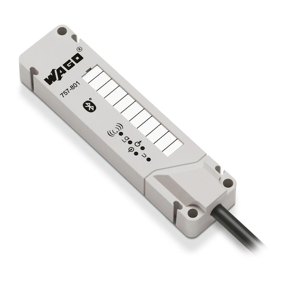
WAGO 757-801 Manual (92 pages)
Bluetooth Module RS-232 For WAGO-I/O-SYSTEM 757
Brand:
WAGO
| Category:
Control Unit
| Size: 2 MB
Table of Contents
Table of Contents
3
1 Notes about this Documentation
7
Validity of this Documentation
7
Copyright
7
Symbols
8
Number Notation
10
Font Conventions
10
Table 1: Number Notation
10
Table 2: Font Conventions
10
2 Important Notes
11
Legal Bases
11
Subject to Changes
11
Personnel Qualification
11
Intended Use of the Product
11
Technical Condition of Specified Devices
11
Safety Advice (Precautions)
12
3 Device Description
15
View
16
Figure 1: View of Device
16
Table 3: Legend for "View of Device" Figure
16
Labeling
17
Figure 2: 757-801 Side Marking/Label (Example)
17
Figure 3: 757-801 Back Marking (Example)
17
Table 4: Legend for Side Marking/Label
17
Connectors
18
Connecting Cable
18
Figure 4: End of Cable in As-Delivered Condition
18
Figure 5: Example of End of Cable with Separated Wires and Wire Mesh (Shield)
18
Table 5: Wire Assignment
18
Antenna
19
Figure 6: Alignment of the WSA
19
Figure 7: Antenna Diagram; Reception Characteristics Based on Device Alignment
20
Table 6: Legend for Antenna Diagram
20
Display Elements
21
Table 7: Indicators in Normal Operation
21
Table 8: Indicators During System Start
22
Table 9: Indicators for Mode Switchover
22
Table 10: Indicators in the "Autoconnect" Mode
22
Technical Data
23
Device Data
23
Connecting Cable
23
Table 11: Technical Data - Device Data
23
Table 12: Technical Data - Connecting Cable
23
Bluetooth Communication
24
Table 13: Technical Data - Bluetooth
24
Approvals
25
4 Function Description
26
Figure 8: WSA as Media Adapter
26
Radio Interface
27
Figure 9: WSA to WSA Link
27
SPP Service "DATA
28
SPP Service "CONFIG
28
AT Command Interface
28
Table 14: SPP Services
28
Figure 10: Link Management
29
Factory Default Settings
30
Table 15: at Command Groups: Section Overview
30
Operating Modes
31
Table 16: Factory Settings
31
Security Settings for the Radio Communications Interface
32
Visibility and Connectivity
32
Table 17: Operating Modes
32
Encryption
33
Authentication
33
Figure 11: Authentication Based on Configuration and Bluetooth ® Standard
35
Special Coexistence Properties
36
Figure 12: Adaptive Frequency Hopping (AFH)
36
Diagnostics Functions
37
5 Mounting
38
Mounting Instructions
38
Direct Mounting on Your System
38
Figure 13: WSA Fixing Holes
39
Table 18: Legend for "WSA Fixing Holes" Figure
39
6 Connect Devices
40
Preparation of Connecting Cable
40
Figure 14: Assembled Connecting Cable
40
Attaching the Connecting Cable
41
Connection Examples
41
Using the WAGO Interface Module 289-383
41
Table 19: Allocation of Wire Colors
41
Figure 15: WAGO 289-383 Interface Module
42
Table 20: Connection to the WAGO 289-383 Interface Module
42
Table 21: Connection to the WAGO 289-383 Interface Module, Power Supply
42
Using the WAGO Interface Module 289-384
43
Figure 16: WAGO 289-384 Interface Module
43
Table 22: Connection to the WAGO 289-384 Interface Module
43
Table 23: Connection to the WAGO 289-384 Interface Module, Power Supply
43
Connecting a PC RS-232 Interface
44
Table 24: Pin Assignment for D-Sub 9-Pole Connector to the 757-801, Data Lines
44
Connecting the 750-652 I/O Module
45
Connecting the 767-5203 Modul
45
Table 25: Pin Assignment for D-Sub 9-Pole Connector to the 757-801, Power Supply
45
Table 26: Connection to the 750-652 I/O Module
45
Table 27: Connection to the 750-652 I/O Module, Power Supply
45
Table 28: Connection to the 767-5203 Module
46
Table 29: Connection to the 767-5203 Module, Power Supply
46
7 Configuration
47
AT Command Interface
47
Using the at Command Interface
47
Opening the at Command Interface
48
Basic Structure of an at Command
49
Figure 17: Welcome Message in Hterm with Windows 7
49
Basic Structure of Replies to at Commands
50
Table 30: Success or Error Codes
50
Table 31: Character Conventions of the at Commands
50
Effectiveness of at Commands
51
8 Commissioning
52
Switching of Operating Modes
52
Switching of Operating Mode by Interrupting the Power Supply
52
Table 32: WSA Operating Modes
52
Figure 18: Operating Mode Status Diagram
53
Table 33: Legend for Status Diagram
53
Switching of Operating Mode Using at Commands
54
Optimizing the Security Settings
54
External Devices Based on Bluetooth
54
External Devices Based on Bluetooth
55
Other Recommendations
55
Example: Connecting to Another WSA
56
Example: Connecting with a Bluetooth Interface in Windows 7
57
Figure 19: Properties of the WSA; "Services" Tab (Example)
58
Example: Configuration with a PC Using the SPP Service "CONFIG
59
Example: Configuration Via RS-232 Using a PC
59
Example: Connecting to an Android Smartphone
61
9 Reference at Commands
63
Group "AT BTID": Identifiers
63
At Btid
63
At Btid Adr
63
At Btid Cod
63
At Btid Help
64
At Btid Name
64
Table 34: Cod Structure
64
Table 35: Cod Structure, Binary
64
Group "AT BTSEC": Security
65
At Btsec Adev
65
AT BTSEC ADEV ADD = <Device
65
AT BTSEC ADEV del = <Index
66
At Btsec Adev Clear
66
At Btsec Auth
66
At Btsec Help
66
At Btsec Inq
67
At Btsec Pag
67
At Btsec Pin
67
Subgroup "AT BTSEC TRUSTED
68
At Btsec Trusted
68
AT BTSEC TRUSTED del = <Index
68
At Btsec Trusted Clear
68
Group "AT CON": Configuration of Outbound Connections
68
At con Auto
69
At con Close
69
At con Help
69
At con Open
69
Subgroup "AT con RETRY
69
AT con RETRY = <Reconnect Cycle
69
At con Retry
69
At con Retry Cycle = 5
70
At con Retry Ena
70
At con Tar
70
At con Tar Adr
70
At con Tar Clear
71
At con Tar Pin
71
At con Tar Port = 0
71
Group "AT ECO": Coexistence Settings
71
Subgroup "AT ECO BLK
71
At Eco Blk
72
AT ECO BLK 15.4 = <Channels
72
AT ECO BLK BT <Channels
72
AT ECO BLK WIFI = <Channels
72
At Eco Blk Clear
73
At Eco Ena
73
At Eco Help
73
At Eco Inq
73
At Eco Txpwr
73
At Eco Txpwr Def
73
At Eco Txpwr Max = 4
74
At Help
74
At Info
75
Group "AT INQ": Search for SPP Devices Within Range
75
At Inq
75
At Inq Cod
75
At Inq Count
75
At Inq Start
76
At Logout
76
At Reset
76
Group "AT RDEV": Devices Within Range
76
At Rdev Found
76
At Rdev Found Names
76
At Rdev Help
77
AT RDEV NAME <Device
77
Subgroup "AT RDEV PORT
77
AT RDEV PORT INDEX <Target Device
77
AT RDEV PORT NAME <Device
78
Group "AT STATUS": Version and Status Information
78
At Status con
78
At Status Hwvers
78
At Status Serial
79
At Status Stats
79
At Status Swvers
79
At Status Uptime
79
Group "AT SYS": Output Format, Factory Default Settings
80
At Sys Cfg Clear
80
At Sys Echo
80
At Sys Help
80
At Sys Output
81
At Sys Usrstr
81
Group "AT UART": Serial Interface Parameters
81
At Uart
81
At Uart Baud
82
At Uart Help
82
At Uart Par
82
At Uart Stopb
82
At Uart Fctrl
82
At Uart Seg
83
Glossary
84
List of Figures
89
List of Tables
90
Advertisement
Advertisement
Related Products
WAGO 750-494/025-000
WAGO 750-513/000-001
WAGO 750-515
WAGO 750-1416/040-000
WAGO 750-532
WAGO 750-651
WAGO 751-5702
WAGO 750-405
WAGO 750-469/000-206
WAGO 750-469/000-008
WAGO Categories
I/O Systems
Control Unit
Power Supply
Switch
Controller
More WAGO Manuals
Login
Sign In
OR
Sign in with Facebook
Sign in with Google
Upload manual
Upload from disk
Upload from URL