Sign In
Upload
Manuals
Brands
VMIC Manuals
Computer Hardware
VMIVME-7487A
VMIC VMIVME-7487A Manuals
Manuals and User Guides for VMIC VMIVME-7487A. We have
1
VMIC VMIVME-7487A manual available for free PDF download: Product Manual
VMIC
VMIVME-7487A
Product Manual
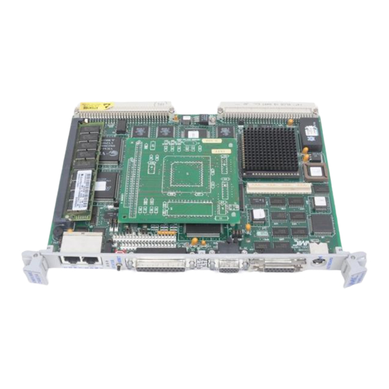
VMIC VMIVME-7487A Product Manual (215 pages)
486 PC/AT VMEbus CPU WITH DUAL-PORT MEMORY, PC/104, AND CACHE
Brand:
VMIC
| Category:
Computer Hardware
| Size: 4 MB
Table of Contents
Table of Contents
8
Chapter 1 - Introduction
21
Section 1 - Introduction to the Vmivme-7487A
21
Section 2 - about this Manual
22
Section 3 - Product Family
23
Section 4 - References
25
Section 5 - Pc/At Features
26
Figure 1-2 VMIVME-7487A Partial Block Diagram
27
Table 1-1 PC/AT I/O Features
28
SECTION 6 - Vmebus FEATURES
28
Chapter 2 - Installation and Setup
32
Section 2 - Unpacking Procedures
32
Section 3 - Hardware Setup
33
Section 4 - Led Status Definition
35
Section 5 - Installation
35
Section 6 - Front Panel Connectors
36
Figure 2-3 PC/104 Mechanical Connection
37
Section 7 - Pc/104 Expansion Site
37
Section 8 - Bios Setup
38
Section 9 - Configuring Operating Systems
38
General Rule Regarding Operating Systems
38
Configuration Examples
39
Configuring MS-DOS for the VMIVME-7487A
39
Configuring Windows for the VMIVME-7487A
40
Chapter 3 - Pc/At Functions
41
Section 1 - Cpu Register Model
41
Section 2 - Physical Memory
42
Section 3 - Memory and Port Maps
43
Memory Map
43
I/O Port Map
44
Table 3-2 VMIVME-7487A I/O Address Map
45
Table 3-3 PC/AT Hardware Interrupts
48
Section 4 - Pc/At Interrupts
48
Table 3-4 PC/AT Interrupt Vector Table
49
Section 5 - Enhanced I/O Ports
52
Serial Ports
53
Parallel Port
53
Table 3-5 Parallel Port Modes
53
Section 6 - Video Graphics Adapter
54
Section 7 - Pc/104 Expansion Site
55
CHAPTER 4 - Vmebus FUNCTIONS
57
Section 1 - Introduction
57
SECTION 2 - Vmebus INTERFACE
58
Vmebus Interface Overview
58
Vmebus Interface Hardware
59
Programming the Vmebus Interface
62
SECTION 3 - Vmebus MASTER OPERATION
63
Real Mode Access
64
Figure 4-4 Real Mode Vmebus Access
65
Protected Mode Access
66
Figure 4-5 Protected Mode Vmebus Access
68
SECTION 4 - Vmebus SLAVE OPERATION
69
Interprocessor Communications
69
Figure 4-6 Vmebus Slave Interface
71
Figure 4-7 Slave Compare Operation
73
Table 4-2 Slave Access Memory Map
78
System Considerations
79
Dual-Ported DRAM
74
Slave Access Memory Map
77
Figure 4-8 Slave Addressing Detail
80
Section 5 - System Controller Functions
81
SECTION 6 - Vmebus INTERRUPT HANDLING
82
Table 4-3 Interrupt Priorities
83
Table 4-4 Interrupt Level Assignments
84
Interrupt on BERR
86
Periodic Timer Interrupt
86
Software Interrupts
86
Interrupt Processing
87
Figure 4-9 Flow Chart for Non-NMI Interrupt Processing for IRQ11
88
Figure 4-10 Flow Chart for NMI Interrupt Processing
89
SECTION 7 - Vmebus INTERRUPTER
89
SECTION 8 - Vmebus REQUESTER
90
Section 9 - Read-Modify-Write Cycles
90
Section 10 - Block Transfers
92
DRAM Refresh Considerations
92
Master BLT Operation
93
Slave BLT Operation
94
Section 11 - Vme64 Functions
95
Master VME64 Operation
95
Slave VME64 Operation
95
Section 12 - Byte Ordering
96
Byte Swapping
96
Figure 4-11 Byte Relationships Using the Little-Endian 80486
97
The Byte Swapping Problem Defined
97
Figure 4-12 Byte Relationships Using the Big-Endian 68040
98
VMIVME-7487A Byte Swapping Hardware
99
Byte Swapping and the Vmebus
98
Table 4-6 Byte Swap Modes
100
Figure 4-13 80486-To-Vmebus Data Byte Lanes
100
Master/Slave Byte Swapping
101
Table 4-8 VIC Register Map
104
Section 13 - Vmivme-7487A Registers
105
Table 4-9 Slave Access Register Map
107
System Register Details
108
General Purpose Command Register
108
Product ID Register
111
VIC Base Register
111
Extended/Standard Address Register
113
Onboard Video Status Register
113
Rearm Interrupt Register
113
Slave Address Mask/Compare Registers
113
Interrupt Acknowledge Register Details
114
VIC Register Details
114
Vmebus Interrupter Interrupt Control Register
115
Vmebus Interrupt Control Registers
116
DMA Status Interrupt Control Register
117
Local Interrupt Control Registers
118
ICGS Interrupt Control Register
119
ICMS Interrupt Control Register
120
Error Group Interrupt Control Register
121
ICGS Interrupt Vector Base Register
122
ICMS Interrupt Vector Base Register
123
Local Interrupt Vector Base Register
124
Error Group Interrupt Vector Base Register
124
Interprocessor Communications Registers
125
Vmebus Interrupt Request/Status Register
125
Vmebus Interrupt Vector Base Registers
126
Local Bus Timing Register
129
Block Transfer Definition Register
130
Interface Configuration Register
131
Arbiter/Requester Configuration Register
133
Address Modifier Source Register
134
Bus Error Status Register
135
DMA Status Register
136
Slave Select 0 Control Register 0
138
Slave Select 0 Control Register 1
141
Slave Select 1 Control Register 0
144
Slave Select 1 Control Register 1
145
Release Control Register
148
Block Transfer Control Register
149
Block Transfer Length Registers
151
System Reset Register
152
Interprocessor Communications Registers
152
Interprocessor Communications Switch Register
153
Interprocessor Communication Registers
154
VIC Version Register
154
Reset/Halt Status Register
154
Mailbox Semaphore Register
155
Set/Clear ICGS Switch Registers (Slave-Only)
157
Set/Clear ICMS Switch Registers (Slave-Only)
157
Chapter 5 - Maintenance
159
Section 1 - Maintenance
159
Section 2 - Maintenance Prints
159
Appendix A - Connector Pinouts
162
Figure A-2 Ethernet Connector Pinout
163
Section 2 - Ethernet Connector Pinout
163
Figure A-3 Floppy Drive Connector Pinout
164
Section 3 - Floppy Drive Connector Pinout
164
Figure A-4 IDE Hard Drive Connector Pinout
165
Section 4 - Ide Hard Drive Connector Pinout
165
Figure A-5 PS/2 Keyboard Connector Pinout
166
Figure A-6 PC/AT Keyboard Connector Pinout
166
Section 5 - Keyboard Connector Pinout
166
Section 6 - Pc/104 Connector Pinout
167
Figure A-7 PC/104 Connector Diagram
167
Table A-1 PC/104 Connector Pinout
167
Section 7 - Printer Connector Pinout
169
Figure A-8 Printer Connector Pinout
169
Section 8 - Serial Connector Pinout
170
Section 9 - Video Connector Pinout
171
Figure A-10 Video Connector Pinout
171
SECTION 10 - Vmebus CONNECTOR PINOUT
173
Appendix B - Ethernet Option
175
Section 1 - Introduction
175
Section 2 - Ethernet Software Compatibility
176
Figure B-1 Location of the Ethernet Mezzanine
176
Section 3 - Ethernet Driver Software
177
Section 4 - Ethernet Diagnostic Software
177
Section 5 - Technical Details
179
Table B-1 Boot EPROM Address Selection
180
Appendix C - Flash Memory Option
181
Section 1 - Introduction
181
Section 2 - Preparing the Flash Memory
182
Section 3 - Copying Files to Flash Memory
183
Section 4 - Using Flash Memory as Boot Device
184
Section 5 - Reprogramming Flash Memory
184
Section 6 - Technical Details
185
Section 7 - Programming
186
Appendix D - Basic Input Output System
188
Section 3 - Quick Setup
188
Section 4 - Program Description
191
User Interface
192
Control Key Summary
193
Table D-1 Phoenixbios Setup Keystroke Actions
193
Section 5 - Program Menus and Menu Items
194
Main Menu
194
System Time
195
System Date
195
Diskette A:/B
195
Video System
195
Large Disk Mode
195
System Memory/ Extended Memory
195
IDE Adapter 0 Master/Ide Adapter 0 Slave Sub-Menus
196
Autotype Fixed Disk
196
Type
197
Cylinders
199
Heads
199
Sectors/Track
199
Write Precomp
199
Memory Cache Sub-Menu
200
Internal Cache
201
External Cache
201
Cache Shadow Region
201
Non-Cacheable Region
201
Memory Shadow Sub-Menu
202
System Shadow
203
Video Shadow
203
Shadow Memory Regions
203
C800 - Cfff
203
D000 - Dfff
203
E000 - Efff
203
Boot Options Sub-Menu
204
Keyboard
205
Boot Sequence
205
SETUP Prompt
206
POST Errors
206
Floppy Check
206
Summary Screen
206
Keyboard Features
207
Numlock
207
Key Click
207
Keyboard Auto-Repeat Rate
208
Keyboard Auto-Repeat Delay
208
SECTION 6 - EXITING the Phoenixbios
208
Exit Menu
208
Save Changes & Exit
209
Discard Changes & Exit
209
Load Default Values
209
Load Previous Values
210
Save Changes
210
Section 7 - Status and Error Messages
210
Advertisement
Advertisement
Related Products
VMIC VMIVME-7586-346
VMIC VMIVME-1129
VMIC VMIVME-3124-2BC
VMIC VMIVME-3124-3BC
VMIC VMIVME-3124-010
VMIC VMICPCI-7755
VMIC VMIVME-7750
VMIC VMIVME-7740
VMIC VMIVME-7697
VMIC VMIVME-7455
VMIC Categories
Motherboard
Computer Hardware
Media Converter
Control Unit
Single board computers
More VMIC Manuals
Login
Sign In
OR
Sign in with Facebook
Sign in with Google
Upload manual
Upload from disk
Upload from URL