Sign In
Upload
Manuals
Brands
Vitrek Manuals
Measuring Instruments
Xitron 2801
Vitrek Xitron 2801 Manuals
Manuals and User Guides for Vitrek Xitron 2801. We have
1
Vitrek Xitron 2801 manual available for free PDF download: User Manual
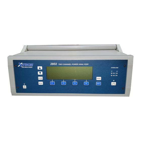
Vitrek Xitron 2801 User Manual (182 pages)
Advanced Single and Dual-Channel Power Analyzers
Brand:
Vitrek
| Category:
Measuring Instruments
| Size: 11 MB
Table of Contents
Table of Contents
5
Introduction
15
Scope
15
Features
16
Functional Description
17
Theory of Operation
17
Figure 1. Overall Block Diagram
17
Analog Channel Board
18
Figure 2. Voltage Input Attenuator Block Diagram
19
Figure 3. Transducer Input Attenuator Block Diagram
20
Figure 4. Current and Line Switch Block Diagram
21
Interfaces
23
Front Panel
23
Ieee488
23
USB Device
23
USB Host
24
Digital I/O
24
Ethernet
24
Using the Power Analyzer
25
Setting up
25
Figure 5. Benchtop Version of 2801 Power Analyzer
25
Using the Front Panel Interface
26
Figure 6. Benchtop Version of 2802 Power Analyzer
26
Figure 7. 2801 Front Panel Interface Detail
27
Figure 8. 2802 Front Panel Interface Detail
27
Figure 9. Sample Display
27
Grounding of the Analyzer
29
Rear Panel Connections - 2801 and 2802
31
Power Requirements
31
2801 Rear Panel Connections
32
Figure 10. Rear Connection Panel
33
Figure 11. Measuring a Power Source, Method 1
34
Single-Channel Measurements of a Power Source: Connection Method 1
34
Figure 12. Measuring a Power Source, Method 2
35
Single-Channel Measurements of a Power Source: Connection Method 2
35
Figure 13. Measuring a Load, Method 1
36
Single-Channel Measurements of a Load: Connection Method 1
36
Figure 14. Measuring a Load, Method 2
37
Single-Channel Measurements of a Load: Connection Method 2
37
Figure 15. Measuring a Source Using a CT, Method 1
38
Measurements of a Power Source:connection Method 1 - Ext CT
38
2802 Rear Panel Connections
39
Measurements of a Power Source: Connection Method 1
39
Figure 16. Rear Connection Panel
39
Measurements of a Power Source: Connection Method 1
40
Figure 17. Measuring a Power Source, Method 1
40
Measurements of a Power Source: Connection Method 2
41
Figure 18. Measuring a Power Source, Method 2
41
Measurements of a Load: Connection Method 1
42
Figure 19. Measuring a Load, Method 1
42
Measurements of a Load: Connection Method 2
43
Figure 20. Measuring a Load, Method 2
43
Measurements of a Power Source and Load: Method 1, Two Ind. Chnls
44
Figure 21. Measuring a Power Source and Load, Method 1, Two Ind. Chnls
44
Measurement: 3P-3W 2 Meter Connection, Method 1
45
Figure 22. Measure 3P-3W 2 Meter Connection, Method 1
45
Measurements of a Power Source: Connection Method 1 - Ext CT
47
Figure 23. Measuring a Source Using a CT, Method 1
47
Using an External Current Transducer
48
Figure 24. External Transducer Test Connections
48
Starting the Analyzer
50
Figure 25. Startup Screen 2801 and 2802
50
Configuring the Power Analyzer 2801/2802
51
Figure 26. Main Menu Screen
51
Getting Started
52
Channel Configuration (2802 Only)
53
Configuring the Analyzer Measurement Results
54
Setting up the Measurement Configuration
56
Figure 27. Measurement Configuration Screen
56
Figure 28. Measurement Configuration Screen
56
Figure 29. Wiring Adjustments Menu Screen
63
Setting up the Ch2 Measurement Configuration (2802 Only)
71
Setup System
71
Figure 30. System Menu Screen
72
Configuration Storage
74
Figure 31. LOAD/SAVE Main Menu Screen
74
Figure 32. Load Configuration Selection Screen
74
Perform DC Zero
75
Diagnostics
75
Figure 33 Erase Configuration Selection Screen
75
Figure 34. DC Zero Screen
75
Figure 35. Diagnostic Menu Screen
76
About
77
Figure 36. Performance Screen
77
Figure 37. about Screen
77
Default Settings
78
Using the Line Switch and Inrush Capabilities
79
Display Screens
82
Viewing Measurement Results
82
Numeric Display Screens
82
Figure 38. ACDC Normal
82
Figure 39. ACDC Inrush
83
Figure 40. ACDC Integrated
83
Figure 41. DC Normal
84
Figure 42. Rectified Normal
84
Figure 43. Fundamental Normal
85
Figure 44. Σharmonics Normal
85
Figure 45. DC Charge & Discharge
85
Figure 46. DC Charge & Discharge
86
Figure 47. Harmonics % Log in Bar Chart
86
Figure 48. Harmonics Absolute in List Form
87
Figure 49. Real-Time Waveform
87
Figure 50. Distortion Waveform
87
Chart Displays
88
Starting Startup and Inrush Charts
88
Line Switch Disabled and Inrush Detection Disabled
88
Line Switch Disabled and Inrush Detection Enabled
88
Line Switch Enabled and Inrush Detection Disabled
88
Line Switch Enabled and Inrush Detection Enabled
89
Chart Formats
89
Figure 51. no Inrush Detected
91
Figure 52. History of Amps ACDC, Trend in Full View
92
Figure 53. History of Amps ACDC, Extents in Full View
92
Figure 54. History of Amps ACDC, Trend in Zoom Mode
92
Figure 55. History of Amps ACDC, Trend; Scrolled
92
Figure 56. History of Amps ACDC, Extents in Zoom Mode
93
Figure 57. Startup in Full View, Trend
95
Figure 58. Startup in Full View, Extents
95
Figure 59. Startup, Partial, Extents
95
Figure 60. Startup, Partial, Extents
95
Figure 61. Startup in Zoom Mode
96
Figure 62. Range Change
97
Figure 63. Amps Inrush in Normal Mode
98
Figure 64. Inrush in Zoom Mode
98
Figure 65. Inrush in Zoom Mode, Additional Zoom Level
98
Printing Results
99
Sample Printouts
99
Figure 66. Configuration Printout
101
Figure 67. Waveform Channel 1 Real-Time
102
Figure 68. Waveform Channe1 Distortion
103
Figure 69. History Chart VOLTS ACDC, Trends View
104
Figure 70. History Chart AMPS PERCENT THD Extents View
105
Figure 71. Harmonics Listing Page 1
106
Figure 72. Harmonics Listing Page 2
107
Sending Commands and Interrogatives
108
Operating Using Multiple Interfaces
108
Interrogatives
108
Usb
109
Rs232
109
Ieee488
109
Remote / Local Operation
109
Resetting the Instrument
110
Initializing an Interface
110
Identifying the Instrument
110
Querying the Date or Time
110
Setting the Date or Time
111
Setting the Interface & Front Panel Language
111
Storing and Recalling Configurations
111
IEEE488 Status Byte Commands
112
Commands Which Affect the Measurement Process
112
Commanding and Controlling a DC Zero
115
Controlling the Line Switch
115
Controlling the Display Backlight & Contrast
115
Configuring Measurements
116
APPLICATION - Application
116
RESULTAVG - Result Averaging Period
117
MSRTYPE - Measurement Type
117
FILTERTYPE - HF Cutoff Filter
118
FILTERFREQ - HF Filter Cutoff Frequency
118
CURRENTSYNC - Use Current Synchronization
118
MINFUND - Minimum Fundamental Frequency
118
MAXFUND - Maximum Fundamental Frequency
119
MAXHARMS - Maximum Number of Measured Harmonics
119
GENDNRANGEDLY - User Set Minimum Downrange Delay
119
MSRDCRIPPLE - DC Ripple Measurement Method
119
RIPPLEFREQ - DC Ripple Base Frequency
120
DCDNRANGEDLY - User Set Minimum Downrange Delay
120
VRANGE - Select a Voltage Input Range
120
AINPUT - Select the Current Input Mode
120
ARANGE - Select a Current Input Range (Shunt Input Only)
121
TRANGE - Select a Current Input Range (Transducer Input Only)
121
STRICTRANGING - Forces the App. of the Requested Fixed Range
121
SHUNTRATIO1 and SHUNTRATIO2 - Sets a Input CT Ratio
122
TRANSRATIO1 and TRANSRATIO2 -Sets T Input CT Ratio
122
MSRSOURCE - Sets Whether the Pwr Source / Load Is to be Meas
123
WIRINGCOMP - Enables Wiring Impedance Compensations
123
WIRINGLOSS - Sets the Wiring Loss Impedance Value
123
WIRINGLOSSN - Neutral Wiring Loss (2802 Only)
123
WIRINGLOSSG - Ground Wiring Loss (2802 Only)
123
VBURDENCOMP - Enables Voltage Burden Compensation
124
REVERSEV - Enables Reversal of Voltage Measurement Polarities
124
REVERSEA - Enables Reversal of Current Measurement Polarities
124
LINECONTROL - Configures the Line Switch
124
LINEPHASE - Internal Line Switch Turn on Phase
124
INRUSHARNG - Sets the a Input Inrush Range
125
INRUSHTRNG - Sets the T Input Inrush Range
125
FILTEREDINRUSH -Filtered or Unfilt. Signal Is Captured During Inrush 125 WAVETRIG - Sets the Method of Triggering Waveform Capture
125
TRIGVOLTS - Sets the Voltage for Waveform Capture Triggering
126
TRIGAMPS - Sets the Current for Waveform Capture Triggering
126
READ and UPDATE Commands
127
Normal Results
129
Highest Measurement During an Inrush & Startup
138
Integrated Results (Scaling in Unit.hours)
139
Integrated Average Results
139
Measurement Extents During Integration
140
Charge & Discharge Data (Scaled in Unit.hours)
143
Special Data
143
Appendix A - Physical Specifications
146
General
146
Environment
146
Altitude Equivalent
146
Warm up
146
Accuracy
146
Appendix B - Measurement Specifications
148
Autorange
148
Ranging
148
Input Filtering
148
Low Frequencies
148
Measurement Rate Frequency
148
Non-Harmonics
149
Harmonics
149
DC Input Offset Compensation
149
Frequency Measurements
149
Harmonic Analysis
149
Result Averaging
150
Input Sampling
150
Integration
150
History Charts
150
Startup Charts
151
Waveform Data
151
Captured Waveforms
151
Inrush Waveforms
151
Line Switch
151
Appendix C-Input & Target Specifications
154
Voltage Input Specifications
154
Transducer (15V) Input Specifications
157
Power Factor Specifications
158
Figure 73. AC Voltage, Autorange
160
Figure 74. AC Voltage, Fixed Range, Low Frequency
161
Figure 75. AC Voltage, Autorange, High Frequency
162
Figure 76. AC Voltage, Fixed Range, High Frequency
163
Figure 77. AC Current, Autorange, Low Frequency
164
Figure 78. AC Current, Fixed Range, Low Frequency
165
Figure 79. AC Current, Autorange, High Frequency
166
Figure 80. AC Current, Fixed Range, High Frequency
167
Figure 81. DC Voltage, Autorange
168
Figure 82. DC Voltage, Fixed Range
169
Figure 83. DC Current, Autorange
170
Figure 84. DC Current, Fixed Range
171
Figure 85. AC Voltage (Transducer), Autorange, Line or LF Measurements
172
Figure 87. AC Voltage, (Transducer), Autorange, HF Measurements
174
Figure 88. AC Voltage, (Transducer), Fixed Range, HF Measurements
175
Figure 89. DC Voltage, (Transducer), Autorange
176
Figure 90. DC Voltage, (Transducer), Fixed Range
177
Figure 91. Power, Autorange
178
Figure 92. Power, Fixed Range
179
Advertisement
Advertisement
Related Products
Vitrek Xitron 2802
Vitrek Xitron 2553
Vitrek Xitron 2553E
Vitrek XiTRON XT560
Vitrek Xitron 6000-2
Vitrek Xitron 6000-3
Vitrek XiTRON XT2640
Vitrek Xitron 2000I
Vitrek Xitron 2000MN
Vitrek Xitron 2000IN
Vitrek Categories
Measuring Instruments
Computer Hardware
Switch
Portable Generator
Test Equipment
More Vitrek Manuals
Login
Sign In
OR
Sign in with Facebook
Sign in with Google
Upload manual
Upload from disk
Upload from URL