Sign In
Upload
Manuals
Brands
Victor Manuals
Welding System
ULTRA-CUT 300 XT
User Manuals: Victor ULTRA-CUT 300 XT Cutting System
Manuals and User Guides for Victor ULTRA-CUT 300 XT Cutting System. We have
2
Victor ULTRA-CUT 300 XT Cutting System manuals available for free PDF download: Operating Manual
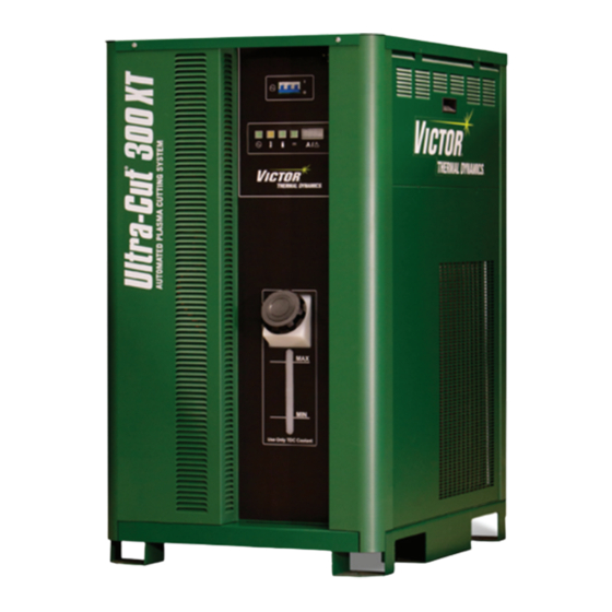
Victor ULTRA-CUT 300 XT Operating Manual (202 pages)
PLASMA CUTTING SYSTEM
Brand:
Victor
| Category:
Welding System
| Size: 23 MB
Table of Contents
Table of Contents
4
Section 1
7
General Information
7
Important Safety Precautions
7
Notes, Cautions and Warnings
7
Publications
8
Note, Attention Et Avertissement
9
Precautions de Securite Importantes
9
Documents de Reference
12
Declaration of Conformity
13
Statement of Warranty
15
Section 2: Specifications
17
General Description of the System
17
Plasma Power Supply
17
Remote Arc Starter
17
Gas Control Module
17
Precision Plasma Cutting Torch
17
Specifications & Electrical Requirements
18
Power Supply Dimensions
20
Power Supply Rear Panel Features
21
Gas Requirements
22
Gas Applications
24
XT Torch Specifications
25
Section 3: Installation
27
Installation Requirements
27
System Layout 100 - 200 Amp
28
System Layout 300 Amp
28
System Layout 400 Amp
29
Recommended Gas Supply Hose
29
Leads and Cables All Amperage
30
Lift the Power Supply
31
Connect Input Power and Ground Cables
32
Connect Work Cable and Pilot and Negative Leads
33
Ground Connections
33
Connect Coolant Leads
36
Connect Cables for CNC, Remote Arc Starter, GCM and HE 400
37
Handling and Installation of Fiber Optics
37
Correct Installation
39
Set Switches on the Command - Control Module
40
Height Control Connections
42
Gas Control Module Installation
42
Fiber Optic Cable Installation
44
Gas Control Module: Control, Input, and Output Connections
45
He400Xt Cooler
47
Install Remote Arc Starter
49
Input Connections
51
Output Connections
53
Torch Valve Installation
56
Connecting Torch
57
Install Consumable Torch Parts
59
Voltage Divider for Ihc Torch Height Control
61
Control Cable
61
Complete the Installation
63
Section 4: Operation
65
Power Supply Control Panel
65
System Operation
66
Gas Selection
68
Functional Overview
70
GCM 2010 Gas Control Module Operation
70
GCM 2010 First Time Operation Matching Gas Control to Lead Length
74
GCM 2010 Sequence of Operation
74
Power Supply Status Codes
77
Remote Arc Starter Trouble Shooting
84
Section 5: Maintenance
85
General Maintenance
85
External Coolant Filter Cleaning Procedure
85
Coolant Replacement Procedure
86
Section 6: Replacement Assemblies & Parts
87
Replacement Power Supply
87
System Layout 100 - 200 Amp
88
System Layout 300 Amp
88
System Layout 400 Amp
89
Recommended Gas Supply Hose
89
Leads and Cables All Amperages
90
Power Supply External Replacement Parts
92
Power Supply Replacement Parts - Upper Right Side
93
Power Supply Replacement Parts - Lower Right Side
94
Power Supply Replacement Parts - Rear Panel
95
Power Supply Replacement Parts - Left Side
96
Gas Control Module (GCM-2010) Replacement Parts
97
Gas Control Module (GCM-2010) Replacement Parts
98
Remote Arc Starter (RAS-1000 XT) Replacement Parts
99
HE400XT Heat Exchanger - Replacement Parts
100
Torch Maintenance
101
Consumable Removal
101
O-Ring Lubrication
102
Parts Wear
102
Torch Consumables Installation
103
Coolant Leak Trouble-Shooting
105
Appendix 1: Remote Arc Starter Schematic
107
Appendix 2: Gas Control and Torch Valve Schematic
108
Appendix 3: Gas Control Module Plumbing Diagram
110
Appendix 4: Gas Control Module Pcb Layout
111
Appendix 5: Gas Control Display Module Pcb Layout
112
Appendix 6: Cnc - Control Module Pcb Connections
113
Appendix 7: Cnc
114
CNC Functions
114
CNC Input / Output Descriptions
116
Simplified CNC Circuit
118
CNC Connections
120
Appendix 8: Serial Communications
121
A8.01 Cables and Switch Settings for 2 and 4 Wire
121
Appendix 9: CCM Cpu Pcb Layout
124
Appendix 10: CCM I/O Pcb Layout
126
Appendix 11: Pilot Pcb Layout
128
Appendix 12: Relay and Interface Pcb Layout
130
Appendix 13: Display Pcb Layout
132
Appendix 14: System Bias Pcb Layout
134
Appendix 15: Main Inverter Bottom Pcb Layout
136
Appendix 16: Main Inverter Top Pcb Layout
138
Appendix 17: Control and Fault Pcb Layout
140
Appendix 18: Cap Bias Bottom Pcb Layout
142
Appendix 19: Cap Bias Top Pcb Layout
143
Appendix 20: Suppressor Pcb Layout
144
Appendix 21: Cooling Diagram
145
Appendix 22: System Schematic 100A, 380-415V
146
Appendix 23: System Schematic 100A, 380-415V
148
Appendix 24: System Schematic 200A, 380-415V
152
Appendix 25: System Schematic 200A, 380-415V Pg 2
156
Appendix 25: System Schematic 200A, 380-415V Pg 2
156
Appendix 26: System Schematic 300A, 380-415V
156
Appendix 27: System Schematic 300A, 380-415V Pg 2
160
Appendix 27: System Schematic 300A, 380-415V Pg 2
160
Appendix 28: System Schematic 400A, 380-415V
160
Appendix 29: System Schematic 400A, 380-415V Pg 2
162
Appendix 29: System Schematic 400A, 380-415V Pg 2
162
Appendix 30: Advanced Troubleshooting
162
Appendix 31: Publication History
200
Advertisement
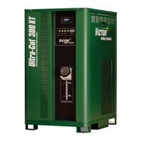
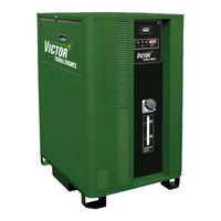
Victor ULTRA-CUT 300 XT Operating Manual (204 pages)
PLASMA CUTTING SYSTEM AUTOMATED GAS CONTROL
Brand:
Victor
| Category:
Welding System
| Size: 36 MB
Table of Contents
Table of Contents
5
Section 1
9
General Information
9
Important Safety Precautions
9
Notes, Cautions and Warnings
9
Publications
10
Note, Attention Et Avertissement
11
Precautions de Securite Importantes
11
Documents de Reference
13
Declaration of Conformity
14
Statement of Warranty
16
Section 2: Specifications
17
General Description of the System
17
Plasma Power Supply
17
Remote Arc Starter
17
Gas Control Module
17
Precision Plasma Cutting Torch
17
Specifications & Electrical Requirements
17
Power Supply Dimensions
18
Power Supply Rear Panel Features
19
Gas Requirements
19
Gas Applications
20
XT Torch Specifications
21
Section 3: Installation
23
Installation Requirements
23
System Layout
24
Recommended Gas Supply Hose
24
Leads and Cables All Amperage
25
Lift the Power Supply
26
Connect Input Power and Ground Cables
27
Connect Work Cable and Pilot and Negative Leads
28
Ground Connections
28
Connect Coolant Leads
30
Connect Cables for CNC, Remote Arc Starter, GCM and HE 400
31
Handling and Installation of Fiber Optics
32
Correct Installation
34
Connect TSC-3000 Cable and DMC-3000 Fiber Optic Cable to CCM
36
Set Switches on the Command - Control Module
37
Height Control Connections
40
DMC-3000 Gas Manifold Control Installation
41
DPC-3000 Gas Pressure Control Installation
44
Fiber Optic Cable Installation from CCM to DMC-3000
47
Fiber Optic Cable Installation from DMC-3000 to DPC-3000
49
Install TSC-3000 Touch Screen Control
51
Install Remote Arc Starter
52
Input Connections
54
Output Connections
55
Connecting Torch
59
Install Consumable Torch Parts
60
Voltage Divider for Ihc Torch Height Control
62
Control Cable
63
Complete the Installation
64
Section 4: Operation
67
Power Supply Control Panel
67
System Operation
67
TSC-3000 Navigation Functions
69
TSC-3000 Initial Setup ONLY
70
TSC-3000 Selecting New Process
71
TSC-3000 Selecting Recently Used Process
72
TSC-3000 Creating a Custom Process
73
Back up and Restoration of Custom Processes
75
Sequence of Operation
78
Gas Selection
81
CCM Status Codes
83
DMC-3000 Status Codes
90
DPC-3000 Status Codes
92
Remote Arc Starter Trouble Shooting
95
Section 5: Maintenance
97
General Maintenance
97
External Coolant Filter Cleaning Procedure
97
Coolant Replacement Procedure
98
Section 6: Replacement Assemblies & Parts
99
Replacement Power Supply
99
System Layout
100
Recommended Gas Supply Hose
100
Leads and Cables All Amperages
101
Power Supply External Replacement Parts
103
Power Supply Replacement Parts - Upper Right Side
104
Power Supply Replacement Parts - Lower Right Side
105
Power Supply Replacement Parts - Rear Panel
106
Power Supply Replacement Parts - Left Side
107
DFC-3000 Automated Gas Control System Replacement Components
108
DMC-3000 Gas Control Module Replacement Parts
109
DPC-3000 Gas Control Module Replacement Parts
110
TSC-3000 Touch Screen Control Remote and Internal Replacement Parts
111
Remote Arc Starter (RAS-1000 XT) Replacement Parts
112
HE 400 Heat Exchanger - Replacement Parts
113
Torch Maintenance
115
Consumable Removal
115
Section 7: Torch Maintenance
115
O-Ring Lubrication
116
Parts Wear
116
Torch Consumables Installation
117
Coolant Leak Trouble-Shooting
119
Appendix 1: Cnc - Control Module Pcb Connections
121
Appendix 2: Cnc
122
CNC Functions
122
CNC Input / Output Descriptions
124
Simplified CNC Circuit
126
CNC Connections
128
Appendix 3: DMC-3000 Control Pcb Layout
129
Appendix 4: Dpc-3000 Control Pcb Layout
130
Appendix 5: DMC-3000 / Dpc-3000 Power Supply Pcb Layout
131
Appendix 6: Tsc-3000 Pcb Layout
132
Appendix 7: CCM Cpu Pcb Layout
134
Appendix 8: CCM I/O Pcb Layout
136
Appendix 9: Pilot Pcb Layout
138
Appendix 10: Relay and Interface Pcb Layout
140
Appendix 11: Display Pcb Layout
142
Appendix 12: System Bias Pcb Layout
144
Appendix 13: Main Inverter Bottom Pcb Layout
146
Appendix 14: Main Inverter Top Pcb Layout
148
Appendix 15: Control and Fault Pcb Layout
150
Appendix 16: Cap Bias Bottom Pcb Layout
152
Appendix 17: Cap Bias Top Pcb Layout
153
Appendix 18: Suppressor Pcb Layout
154
Appendix 19: Cooling Diagram
155
Appendix 20: Remote Arc Starter Schematic
156
Appendix 21: Schematic, Dfc-3000 Auto Gas Box System
158
Appendix 22: System Schematic 300A, 480V
160
Appendix 23: System Schematic 300A, 480V
162
Appendix 24: Advanced Troubleshooting
164
Power Supply Status Codes
168
Appendix 25: Publication History
202
Advertisement
Related Products
Victor ULTRA-CUT 100 XT
Victor ULTRA-CUT 200 XT
Victor 42 CUTMASTER
Victor Auto-Cut 200 XT
Victor AUTO-CUT 300 XT
Victor CUTMASTER 102
Victor CUTMASTER 120
Victor CUTMASTER 152
Victor Cutmaster 52
Victor cutmaster 82
Victor Categories
Calculator
Multimeter
Commercial Food Equipment
Welding System
Turntable
More Victor Manuals
Login
Sign In
OR
Sign in with Facebook
Sign in with Google
Upload manual
Upload from disk
Upload from URL