Sign In
Upload
Manuals
Brands
VIA Technologies Manuals
Motherboard
EPIA-M860-12PE
VIA Technologies EPIA-M860-12PE Manuals
Manuals and User Guides for VIA Technologies EPIA-M860-12PE. We have
1
VIA Technologies EPIA-M860-12PE manual available for free PDF download: User Manual
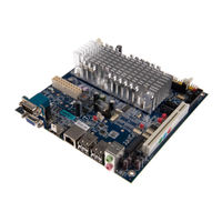
VIA Technologies EPIA-M860-12PE User Manual (84 pages)
EPIA-M860 series. Mini-ITX embedded board
Brand:
VIA Technologies
| Category:
Motherboard
| Size: 4 MB
Table of Contents
Regulatory Compliance
2
Table of Contents
5
1 Product Overview
12
Key Features and Benefits
12
VIA Nano™ 1.2Ghz Processor
12
VIA VX900 Chipset
12
Flexible Power Options
12
Modular Expansion Options
12
Product Specifications
13
Layout Diagram
16
Figure 1: Layout Diagram of the EPIA-M860 Mainboard
16
Product Dimensions
17
Figure 2: Mounting Holes and Dimensions of the EPIA-M860 Mainboard
17
Figure 3: External I/O Port Dimensions of the EPIA-M860 Mainboard
17
Height Distribution
18
Figure 4: Height Distribution of the EPIA-M860 Mainboard
18
2 I/O Interface
19
External I/O Ports
19
Figure 5: External I/O Ports
19
Figure 6: HDMI ® Port Pinout Diagram
20
HDMI ® Port
20
Table 1: HDMI ® Port Pinout
20
Figure 7: VGA Port Pinout Diagram
21
Table 2: VGA Port Pinout
21
VGA Port
21
COM Port
22
Figure 8: COM Port Pinout Diagram
22
Figure 9: USB Port Pinout Diagram
22
Table 3: COM Port Pinout
22
Table 4: USB Port Pinout
22
USB Ports
22
Figure 10: Gigabit Ethernet Port Pinout Diagram
23
Gigabit Ethernet Port
23
Table 5: Gigabit Ethernet Port Pinout
23
Audio Ports
24
DC-In Jack
24
Figure 11: Audio Jack Receptacle Stack
24
Figure 12: DC-In Coaxial Connector
24
Table 6: Audio Jack Receptacle Pinout
24
Table 7: DC-In Coaxial Connector Specifications
24
Onboard Connectors
25
ATX Power Connector
25
Table 8: ATX Power Connector Pinout
25
Figure 13: ATX Power Connector
25
DC-In Power Connector
26
Table 9: DC-In Power Connector Pinout
26
Figure 14: DC-In Power Connector
26
SATA Power Connector
27
Table 10: SATA Power Connector Pinout
27
Figure 15: SATA Power Connector
27
CMOS Battery Slot
28
Table 11: CMOS Battery Slot/Connector Pinout
28
Figure 16: CMOS Battery Slot/Connector
28
Front Panel Pin Header
29
Smbus Pin Header
29
Table 12: Front Panel Pin Header Pinout
29
Table 13: Smbus Pin Header Pinout
29
Figure 17: Front Panel Pin Header Block
29
Figure 18: Smbus Pin Header
29
Thermal Resistor Pin Header
30
Fan Connectors
30
Table 14: Thermal Resistor Pin Header Pinout
30
Table 15: Fan Connector Pinouts
30
Figure 19: Thermal Resistor Pin Header
30
Figure 20: Fan Connectors
30
SATA Connectors
31
Table 16: SATA Connector Pinouts
31
Figure 21: SATA Connectors
31
USB Pin Headers
32
Figure 22: USB Pin Headers
32
COM Pin Headers
33
Table 17: COM Pin Header Pinout
33
Figure 23: COM Pin Headers
33
PS/2 Keyboard and Mouse Pin Header
34
Table 18: PS/2 Keyboard and Mouse Pin Header Pinout
34
Figure 24: PS/2 Keyboard and Mouse Pin Header
34
Front Audio Pin Header
35
Table 19: Front Audio Pin Header Pinout
35
Figure 25: Front Audio Pin Header
35
Digital I/O Pin Header
36
Table 20: Digital I/O Pin Header Pinout
36
Figure 26: Digial I/O Pin Header
36
SPI Pin Header
37
Table 21: SPI Pin Header Pinout
37
Figure 27: SPI Pin Header
37
3 Jumpers and Switches
38
AT/ATX Mode
38
Table 22: AT/ATX Mode Jumper Settings
38
Figure 28: AT/ATX Mode Jumper
38
SATA DOM Power Select Jumper
39
Table 23: SATA DOM Voltage Select Jumper Settings
39
Figure 29: SATA DOM Voltage Select Jumper
39
Clear CMOS Jumper
40
Table 24: CLEAR CMOS Jumper Settings
40
Figure 30: CLEAR CMOS Jumper
40
COM Voltage Select Jumpers
41
COM2 Voltage Select Jumper
41
Table 25: COM2 Voltage Select Jumper Settings
41
Figure 31: Voltage Select Jumpers for COM2 - COM6
41
COM3 and COM4 Voltage Select Jumper
42
COM5 and COM6 Voltage Select Jumper
42
Table 26: Jumper Settings for COM3 and COM4
42
Table 27: Jumper Settings for COM5 and COM6
42
4 Expansion Slots
43
DDR3 Memory Slot
43
Figure 32: DDR3 Memory Slot
43
Figure 33: Installing Memory 1
44
Figure 34: Installing Memory 2
44
Installing a Memory Module
44
Figure 35: Removing Memory 1
45
Figure 36: Removing Memory 2
45
Removing a Memory Module
45
Mini Pcie Slot
46
Figure 37: Mini Pcie Slot
46
PCI Express Slot
47
Figure 38: PCI Express Slot
47
PCI Slot
48
Figure 39: PCI Slot
48
5 Hardware Installation
49
Installing into a Chassis
49
Suggested Minimum Chassis Dimensions
49
Figure 40: Suggested Minimum Chassis Dimensions
49
Suggested Minimum Chassis Height
50
Figure 41: Suggested Minimum Internal Chassis Ceiling Height
50
Suggested Keepout Areas
51
Figure 42: Suggested Keepout Areas
51
6 BIOS Setup Utility
52
Entering the BIOS Setup Utility
52
Control Keys
52
Getting Help
52
System Overview
53
Amibios
53
Processor
53
System Memory
53
System Time
53
System Date
53
Figure 43: Illustration of the Main Menu Screen
53
Advanced Settings
54
Figure 44: Illustration of the Advanced Settings Screen
54
CPU Configuration
55
CPU Thermal Control
55
Figure 45: Illustration of the CPU Configuration Screen
55
IDE Configuration
56
Hard Disk Information
56
Figure 46: Illustration of IDE Configuration Screen
56
Figure 47: Illustration of Primary IDE Master Screen
56
Superio Configuration
57
Serial Ports 1 to 4
57
Table 28: Serial Port Addresses and Irqs
57
Figure 48: Illustration of Superio Configuration Screen
57
Figure 49. Illustration of Hardware Health Configuration Screen
58
Hardware Health Configuration
58
ACPI Configuration
59
Suspend Mode
59
Figure 50: Illustration of ACPI Configuration Screen
59
APM Configuration
60
Power Button Mode
60
Restore on Ac/Power Loss
60
Resume on PS/2 KBC
60
Figure 51: Illustration of APM Configuration Screen
60
Wake-Up Key
61
Wake-Up Password
61
Resume on PS/2 Mouse
61
Resume on Software RTC Alarm
61
Resume on RTC Alarm
61
RTC Alarm Date (Days)
61
System Time
62
Spread Spectrum Configuration
63
Spread Spectrum Setting
63
Figure 52: Illustration of Spread Spectrum Configuration Screen
63
USB Configuration
64
Onchip UHCI Device
64
Onchip EHCI Device
64
Legacy USB Support
64
USB 2.0 Controller Mode
64
Figure 53: Illustration of USB Configuration Screen
64
CRB Configuration
65
VT6130 LAN Control
65
LAN Option ROM
65
Figure 54: Illustration of CRB Configuration Screen
65
Advanced Pci/Pnp Settings
66
Clear NVRAM
66
Plug & Play O/S
66
PCI Latency Timer
66
Allocate IRQ to PCI VGA
66
Palette Snooping
66
Figure 55: Illustration of Advanced Pci/Pnp Settings Screen
66
PCI IDE Busmaster
67
Irq3~15
67
DMA Channel 0~7
67
Reserved Memory Size
67
Hotplug Reserve I/O Port Size
67
Hotplug Reserve Memory Size
67
Hotplug Reserve Pfmemory Size
67
Boot Settings
68
Boot Settings Configuration
68
Quick Boot
68
Quiet Boot
68
Addon ROM Display Mode
68
Bootup Num-Lock
68
PS/2 Mouse Support
68
Figure 56: Illustration of Boot Settings Screen
68
Figure 57: Illustration of Boot Settings Configuration Screen
68
Wait for 'F1' if Error
69
Hit 'DEL' Message Display
69
Interrupt 19 Capture
69
Security Settings
70
Change Supervisor Password
70
Figure 58: Illustration of Security Settings Screen
70
Password Check
71
Advanced Chipset Settings
72
North Bridge VIA VX900 Configuration
72
DRAM Clock/Timing Configuration
72
Figure 59: Illustration of Advanced Chipset Settings Screen
72
Figure 60: Illustration of North Bridge VIA VX900 Configuration Screen
72
Figure 61: Illustration of DRAM Frequency/Timing Configuration Screen
72
AGP & P2P Bridge Configuration
73
Figure 62: Illustration of AGP & P2P Bridge Configuration Screen
73
Onchip VGA Configuration
74
Figure 63: Illustration of Onchip VGA Configuration Screen
74
South Bridge VIA VX900 Configuration
75
SATA Gen2 Support
75
Onchip HDAC Device
75
Serial ATA Controller
75
HPET Support
75
WATCHDOG Timer Enable
75
WATCHDOG Timer RUN/STOP
75
WATCHDOG Timer ACTION
75
WATCHDOG Timer COUNT
75
Keyboard/Mouse Wakeup Control
75
PCI LAN S5 Wakeup
76
Eup/Erp Lot6 Support
76
Exit Options
77
Save Changes and Exit
77
Discard Changes and Exit
77
Discard Changes
77
Load Optimal Defaults
77
Figure 65: Illustration of Exit Options Screen
77
7 Driver Installation
78
Microsoft Driver Support
78
Linux Driver Support
78
Appendix A. Power Consumption Report
79
Epia-M860
79
Playing Dvds (ATX)
79
Playing Dvds (DC-In)
79
Playing Mp3S (ATX)
79
Playing Mp3S (DC-In)
80
Copying Files on a Network (ATX)
80
Copying Files on a Network (DC-In)
80
Idle (ATX)
80
Idle (DC-In)
80
Ccwinstone2004 (Atx)
81
CCWINSTONE2004 (DC-In)
81
S3 (Atx)
81
S3 (DC-In)
81
Appendix B. Riser Card Modules
82
Pcie-03
82
Figure 66: Installing the PCIE-03 Riser Card
82
Ext-Pci-01
83
Figure 67: Installing the EXT-PCI-01 Riser Card
83
Appendix C. Mating Connector Vendor Lists
84
Table 29: EPIA-M860 Mating Connector Vendor Lists
84
Advertisement
Advertisement
Related Products
VIA Technologies EPIA-M840
VIA Technologies EPIA-M800
VIA Technologies EPIA-M830
VIA Technologies EPIA-M850
VIA Technologies epia-m860
VIA Technologies EPIA-M860-12E
VIA Technologies EPIA-M840-16
VIA Technologies EPIA-M840-12
VIA Technologies EPIA-ML8000AG - VIA Motherboard - Mini ITX
VIA Technologies EPIA MII-Series Mini-ITX
VIA Technologies Categories
Motherboard
Computer Hardware
Desktop
Control Unit
Industrial PC
More VIA Technologies Manuals
Login
Sign In
OR
Sign in with Facebook
Sign in with Google
Upload manual
Upload from disk
Upload from URL