Sign In
Upload
Manuals
Brands
Vertiv Manuals
UPS
Liebert NXL 500
Vertiv Liebert NXL 500 UPS System Manuals
Manuals and User Guides for Vertiv Liebert NXL 500 UPS System. We have
2
Vertiv Liebert NXL 500 UPS System manuals available for free PDF download: Operation And Maintenance Manual, Installation Manual
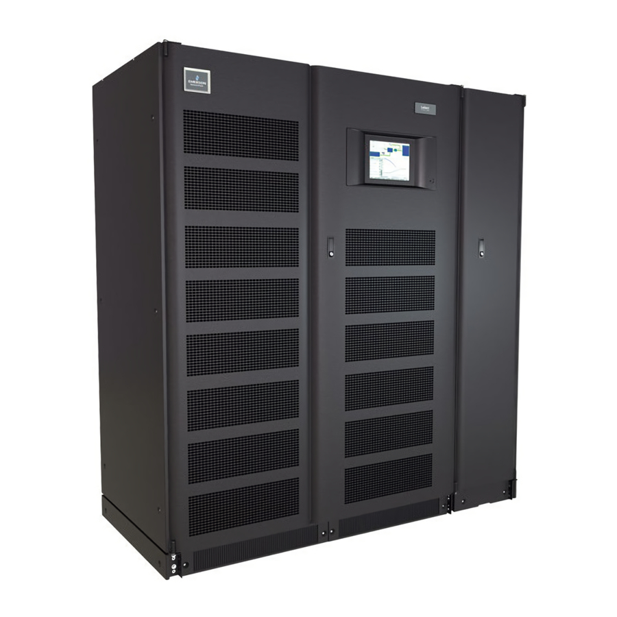
Vertiv Liebert NXL 500 Operation And Maintenance Manual (109 pages)
250-1100kVA, 60Hz, Three Phase, Single-Module & Multi-Module UPS
Brand:
Vertiv
| Category:
UPS
| Size: 5.66 MB
Table of Contents
Precautions
3
Table of Contents
4
Contactingv Ertiv for Support
3
Important Safety Instructions
10
1 Introduction
11
General Description
11
Modes of Operation
11
Normal Mode
11
Bypass Mode
11
Figure 1 Typical Single Module UPS System One-Line Diagram
11
Battery Mode
12
Maintenance Bypass
12
ECO Mode
12
Intelligent Paralleling
12
Options
12
2 Operation
13
Features
13
Figure 2 Main Component Locations-250 to 400Kva
13
Main Component Locations-500Kva
14
Figure 4 Main Components, 625Kva Liebert NXL, N+1 Multi-Module Unit Without Static Bypass
15
Figure 5 Main Components, 625Kva Liebert NXL UPS, SMS and 1+N Multi-Module Unit with Static
15
Figure 6 Main Component Locations-750Kva with Static Bypass
16
Figure 7 Main Component Locations-750Kva Without Static Bypass
16
Figure 8 Main Component Locations-800Kva with Static Bypass
17
Figure 9 Main Components, 1+N Multi-Module or SMS with Static Bypass, 1100Kva UPS
18
Figure 10 Main Components, 1100Kva UPS N+1 Multi-Module Without Static Bypass
19
Figure 11 Main Display Screen, Typical
20
Figure 12 MIMIC Display
20
Figure 13 Monitor/MIMIC Display Example: Normal Power Flow
21
Figure 14 Monitor/MIMIC Display Example: Utility Fail
21
Touchscreen Navigation
22
Main Display Screen
22
Figure 15 Monitor/MIMIC Display Example: Load on Bypass, UPS on
22
Figure 16 Monitor/MIMIC Display Example: Load on Bypass, UPS Module off
22
Configurations Menu
23
Figure 18 System Settings Parameters
24
Figure 19 Adjustable Setpoints Parameters
25
Figure 20 Battery Equalize Settings
26
Event Management
27
Figure 21 Battery Management Parameters
27
Status Reports Menu
28
Startup Menu
28
Figure 22 Typical Event Management Parameters
28
Shutdown Menu
29
Transfer Menu
29
Battery Management Menu
29
Figure 23 UPS Shutdown Pop-Up
29
Figure 24 System Shutdown Pop-Up
29
Figure 25 Time Remaining Display
30
Figure 26 Battery Cycle Monitor
31
Figure 27 Battery Cycle Monitor Summary
31
System View-1+N Systems Only
32
Figure 28 Status View - 1+N Systems Only
32
Metering
33
Help
33
Reset
33
Silence
33
Modes of Operation
33
Load on Bypass
33
Figure 29 1+N Status View
33
OK to Transfer
34
Figure 30 Load on Bypass (UPS Not Available)
34
Figure 31 Load on Bypass, UPS Available
34
Input Power Failure-Load on DC Source
35
Off DC Source
35
Figure 32 Load on UPS, Bypass Available
35
Figure 33 Input Power Fail, Load on DC Source
35
Emergency Module off (Optional)
36
Figure 34 Load on UPS, DC Source Not Available
36
Figure 35 Emergency Modules off
36
Remote Emergency Power off
37
ECO Mode
37
Figure 36 Remote Emergency Power off
37
Figure 37 ECO Mode Power Flow
37
Manual Operations-All Systems
38
Startup-Single Module System
38
Figure 38 Startup Commands
40
Startup-N+1 System
41
Startup-1+N System
42
Figure 39 1+N System Start Menu Commands
43
Load Transfer and Retransfer-Single Module System
45
Maintenance Bypass Load Transfers-Single Module System
46
Figure 40 UPS with Two-Breaker Bypass Cabinet
46
Load Transfer-N+1 System: Remove UPS from N+1 System (Collective)
47
Load Transfer-N+1 System: Add UPS to N+1 System (Collective)
48
Figure 41 N+1 Transfer Menu Commands
48
Load Transfer-1+N System: Remove a UPS from System (Collective)
49
Load Transfer-1+N System: Add a UPS to the System (Collective)
49
Figure 42 1+N UPS Transfer to Bypass Menu Commands
49
Figure 43 1+N UPS Transfer to Inverter Menu Commands
50
Load Transfer-1+N System: Transfer System to Bypass
51
Load Transfer-1+N System: Transfer System to Inverter
51
Load Transfer-1+N System: Transfer to Maintenance Bypass
51
Figure 44 1+N System Transfer Menu Commands
51
Shutdown-Single Module UPS System
52
Shutdown-N+1 UPS System
53
Shutdown-1+N UPS: UPS Shutdown
54
Figure 45 N+1 Shutdown Menu Commands
54
Shutdown-1+N UPS: System Shutdown
55
1+N System Shutdown
55
Figure 46 1+N UPS Shutdown Menu Commands
55
Figure 47 1+N System Shutdown Menu Commands
56
Automatic Operations
57
Overloads (Without Transfer)
57
Figure 48 Current-Versus-Time Curves of Overload Capacity
57
Automatic Transfers to Bypass (Overload Condition)
58
Automatic Transfers to Bypass, UPS System Faults
58
Automatic Retransfers to UPS
59
3 Options
60
Input Contact Isolator Board
60
Figure 49
60
Figure 49 Input Contact Isolator Dialog Box
60
Figure 50 Optional Input Contact Isolator Board
61
Table 1 Input Contact Isolator Board Pre-Assigned Values
61
Table 2 Input Contact Isolator Board Control Wiring Connections
61
Programmable Relay Board
62
Figure 51 Control Wiring, Programmable Relay Board
62
Table 3 Programmable Relay Board Pinout
62
Configuring the Programmable Relay Board Settings
63
Figure 52 Programmable Relay Board Dialog Box
63
Remote Alarm Status Panel RAS
64
Lamp Test/Reset Push Button
64
Audio Reset Push Button
64
Digital Load Bus Sync
64
System Description
64
RAS Indicators
64
LBS Configurations
65
Normal Operations
65
Slave Priority
65
Master System
65
Figure 53 LBS Configuration
65
Slave System
66
ECO Mode
66
ECO Mode Setup
66
Figure 54 ECO Mode Settings
66
Operation
67
Figure 55 ECO Mode Scheduling-Overall and Example
67
Bypass Qualification Limits
68
Conditions to Activate ECO Mode
68
Conditions to Suspend ECO Mode
68
Conditions to Terminate ECO Mode
68
Intelligent Paralleling
69
Intelligent Paralleling Setup
69
Figure 56 Intelligent Paralleling Settings
69
Intelligent Paralleling Target Area
70
Conditions to Activate Intelligent Paralleling
70
Conditions to Suspend Intelligent Paralleling
70
Intelligent Paralleling Module Selection
70
Module Standby Rotation
71
Figure 57 Module Standby Rotation
72
4 Maintenance
73
Safety Precautions
73
Liebert Services
74
Professional Startup
74
Routine Maintenance
75
Record Log
75
Air Filters
75
Limited Life Components
75
Battery Maintenance
76
Table 5 UPS Component Service Life
76
Battery Safety Precautions
77
Battery Voltage, Nominal and Float
78
Table 7 Battery Retorque Values
78
Detecting Trouble
79
Reporting a Problem
79
Corrective Actions
79
Upstream Feeder Circuit Breaker Setting Inspections
80
5 Specifications
81
DC Sources
81
Battery Operation
81
Other DC Sources
81
Environmental Conditions
81
Table 10 Liebert NXL Physical Parameters
83
Ppendixa - Ups Alarm and Status Essages
84
Table 11 Liebert NXL Alarm and Status Messages
84
Advertisement
Vertiv Liebert NXL 500 Installation Manual (73 pages)
Large System, 3-Phase UPS Battery System
Brand:
Vertiv
| Category:
UPS
| Size: 13.96 MB
Table of Contents
Attery Abinet Recautions
3
Table of Contents
4
Important Safety Instructions
8
1 0 Mechanical Installation
10
Introduction
10
Preliminary Checks
10
Environmental Considerations
10
Battery Room
10
Storage for Delayed Installation
10
Positioning
11
Moving the Cabinets
11
Figure 1 Shipping Bolts-Top-Terminal Battery Cabinet, Standard Width
12
Figure 2 Shipping Bolts-Top-Terminal Battery Cabinet, Reduced Width
12
Clearances
13
Raised Floor Mounting
13
System Composition
13
2 0 Battery Installation
14
Safety
14
Layout
15
Figure 3 Top-Terminal Battery System Configurations-Liebert Exl
15
Figure 4 Top-Terminal Battery System Configurations-Liebert NX
16
Figure 5 Top-Terminal Battery System Configurations-Liebert NXL
17
Figure 6 Top-Terminal Stand-Alone Battery System Configuration-Liebert Exl
18
Figure 7 Top-Terminal Battery System Configuration-Battery Cabinets Not Attached to UPS or each Other, Liebert Exl Liebert NX ™ and Liebert NXL
18
Figure 8 Front-Terminal Battery System Configurations-Liebert Exl
19
Figure 9 Front-Terminal Battery System Configurations-Liebert NX
20
Figure 10 Front-Terminal Battery System Configurations-Liebert NXL
21
Cable Entry
22
Power Connection
22
Connected System
22
Figure 11 Front-Terminal Stand-Alone Battery System Configuration-Liebert Exl ™ , Liebert NX ™ and Liebert NXL ™ , All Ratings
22
Figure 12 Front-Terminal Battery System Configuration-Battery Cabinets Not Attached to UPS or each Other, Liebert Exl ™ , Liebert NX ™ and Liebert NXL
22
Connected or Stand-Alone Arrangement
23
Grounding
23
Control Connections
23
3 Installation Drawings
23
Figure 13 Control Cable Layout-Liebert UPS to Liebert Battery Cabinet
23
Liebert NX ™ and Liebert NXL
24
Figure 14 TB3 Location-225-300Kva Liebert NX
24
SMS and 1+N Multi-Module Unit with Static Bypass
24
Table 1 Liebert Exl UPS Control Contacts to Battery Interface Boards
24
Table 2 Liebert NX UPS Control Contacts to Battery Interface Boards
24
Figure 15 TB3 Location-400-600Kva Liebert NX
25
Figure 16 Wiring External Interface Board in Liebert NXL to Battery Interface Board in Battery Cabinet
26
Figure 17 Battery Temperature Sensor Control Connection
27
Figure 18 Outline Drawing, Liebert Top-Terminal, 47" (1194Mm) Wide Battery Cabinet
28
Figure 19 Main Components, Liebert Top-Terminal, 47" (1194Mm) Wide Battery Cabinet
29
Figure 20 Terminal Details, Liebert Top-Terminal, 47" (1194Mm) Wide Battery Cabinet
30
Figure 21 Outline Drawing, Liebert Top-Terminal, 55" (1400Mm) Wide Battery Cabinet
31
Figure 22 Main Components, Top-Terminal, 55" (1400Mm) Wide Battery Cabinet
32
Figure 23 Terminal Details, Top-Terminal, 55" (1400Mm) Wide Battery Cabinet
33
Figure 24 Outline Drawing, Liebert Front-Terminal Battery Cabinet
34
Figure 25 Main Components, Liebert Front-Terminal Battery Cabinet
35
Figure 26 Terminal Details, Liebert Front-Terminal Battery Cabinet
36
Figure 27 Front-Terminal Battery Cabinet Shipping Split
37
Figure 28 Liebert Stand-Alone 32" (813Mm) Junction Cabinet Terminal Wiring
38
Figure 29 Liebert Attached Junction Cabinet-Terminal Details
39
Figure 30 Liebert 15-1/2" Attached Junction Cabinet-Outline Drawing
40
Figure 31 17" Junction Cabinet Junction Cabinet
41
Figure 32 Liebert Battery Cabinet Control Wiring
42
Figure 33 Attached Battery Cabinet Connections
43
Figure 34 Ground Strap Location for Connected Cabinets
43
Figure 35 Top-Terminal, Standard Width Battery Cabinet Interconnection Wiring to 250-400Kva UPS
44
Table 3 Top-Terminal Battery Cabinet Interconnection Wiring to 250-400Kva UPS
44
Figure 36 Liebert Top-Terminal, Standard Width Battery Cabinet Interconnect Wiring to Liebert
45
Stand-Alone Junction Cabinet
47
Wiring
47
Table 6 Terminal Details Liebert NXL 250-400Kva Front-Terminal Battery and Stand-Alone Junction
47
Figure 39 Terminal Details, Liebert NXL
48
Wiring
48
Figure 40 Terminal Details, Liebert NXL
49
Point-To-Point Wiring
49
Table 8 Terminal Details, Liebert NXL 500Kva UPS to Top-Terminal Battery and Stand-Alone
49
Figure 41 Terminal Details Liebert NXL ™ 500Kva to Top-Terminal Battery Point-To-Point Wiring
50
Table 9 Terminal Details Liebert NXL 500Kva to Top-Terminal Battery Point-To-Point Interconnect
50
Figure 42 Terminal Details Liebert NXL ™ 500Kva to Front-Terminal Battery Point-To-Point Wiring
51
Point-To-Point Wiring
52
Table 11 Liebert NXL Terminal Details UPS 625/750Kva to Front-Terminal Battery and Attached
52
Table 12 Liebert NXL Terminal Details UPS 625/750Kva to Front-Terminal Battery and Stand-Alone
53
Table 14 Terminal Details, Liebert NXL 625/750Kva UPS to Top-Terminal Battery and Stand-Alone
55
Figure 48 Terminal Details 625/750Kva UPS to Front-Terminal Battery and Attached Junction Cabinet
57
Table 16 Terminal Details 625/750Kva UPS to Front-Terminal Battery and Attached Junction
57
Figure 49 Terminal Details 625/750Kva to Front-Terminal Battery and Stand-Alone Junction Cabinet
58
Table 17 Terminal Details 625/750Kva to Front-Terminal Battery and Stand-Alone Junction Cabinet
58
Figure 50 Typical Alber ® Battery Monitoring Connections
59
Figure 51 Alber ® Battery Monitoring Wiring to Multiple Battery Cabinets
60
Battery Monitoring Assembly Diagram
61
Table 18 Alber Battery Monitoring Assembly Connections
61
Figure 53 Top-Terminal Battery Configuration
62
Figure 54 Front-Terminal Battery Configuration
63
Figure 55 Busbar Connection between Battery Cabinet and Attached Junction Cabinet
64
Table 22
65
Table 19 Liebert NXL ™ Battery Cabinet Specifications
65
Junction Cabinet Specifications
66
Table 21 Alber ® Battery Monitoring Option Specifications
66
Table 22 Battery Cabinet Weights and Breaker Frame Size
67
Table 23 Torque Specifications, Unless Otherwise Labeled
68
Advertisement
Related Products
Vertiv Liebert NXL 500kVA
Vertiv Liebert NXL625kVA
Vertiv Liebert NXL750kVA
Vertiv Liebert NXL 250
Vertiv Liebert NXL 300
Vertiv Liebert NXL 400
Vertiv Liebert NXL 625
Vertiv Liebert NXL 750
Vertiv Liebert NXL 800
Vertiv Liebert NXL 1100
Vertiv Categories
UPS
Power Supply
Switch
Power distribution unit
Air Conditioner
More Vertiv Manuals
Login
Sign In
OR
Sign in with Facebook
Sign in with Google
Upload manual
Upload from disk
Upload from URL