Sign In
Upload
Manuals
Brands
Vertiv Manuals
UPS
Liebert APM
Vertiv Liebert APM Scalable UPS Solution Manuals
Manuals and User Guides for Vertiv Liebert APM Scalable UPS Solution. We have
1
Vertiv Liebert APM Scalable UPS Solution manual available for free PDF download: User Manual
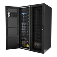
Vertiv Liebert APM User Manual (73 pages)
30 - 150kW, Single Module and Parallel System
Brand:
Vertiv
| Category:
UPS
| Size: 2 MB
Table of Contents
Safety Precautions
2
Table of Contents
5
Chapter 1 Installation of UPS Rack Unit
10
Introduction
10
Initial Checking
10
Location
10
UPS Location
10
External Battery Room
11
Storing
11
Positioning
11
System Cabinet
12
Mooving the Cabinets
12
Transporting the Cabinets
12
Clearances Required for Operating
12
Front Access
12
Final Positioning
12
Installation of Adjustable Feet
12
UPS Composition
13
Installing Power Modules and Battery Modules
13
Fig. 1-1: UPS Structure
13
Tab. 1-1: UPS Configuration List
13
Fig. 1-2: Installing Power Modules
14
Tab. 1-2: DIP Switch Setting Method
14
Cable Entry
15
External Protective Devices
16
Rectifier and Bypass Input Supply of the UPS
16
External Battery
16
Fig. 1-3: the Symbols of RCCB
16
UPS Output
17
Power Cables
17
Tab. 1-3 Maximum Steady State AC and DC Current
17
Cable Connections
18
Tab. 1-4: Distances from Floor to Connection Points
18
Control Cabling and Communication
19
Input and Output Interfaces
19
Back Feed Protection Interface (J5)
19
Fig. 1-4: Bypass Module
19
External Battery Circuit Breaker Interface (J6)
20
Other Input Interface (J7)
20
Fig. 1-6: Connections of Output Dry Relay Contacts
20
Tab. 1-6: External Battery Circuit Breaker Interface
20
Tab. 1-8: Relay Dry Contact Output Port
20
Battery Temperature Sensor Interface (J8)
21
Fig. 1-5: Input Dry Contact Interface
21
Tab. 1-5: Description of Dry Contact Input Port
21
Internal and External Maintenance Bypass Interface (J9)
22
EPO Input Port (J10)
22
Fig. 1-7: Connections of EPO
22
Tab. 1-7: External Maintenance Bypass Cabinet Interface
22
Tab. 1-9: EPO Input Dry Contact Relay
22
Other Interfaces
23
Chapter 2 Battery Installation
24
General Recommendations
24
LIEBERT APM Battery Typologies
25
Safety
25
Modular Battery Cabinet
25
Fig. 2-1: Battery Box Back
25
Battery Installation
26
Battery Maintenance
27
Chapter 3 Installation of a Parallel USP Rack System
28
Overview
28
UPS Rack Systems in Parallel System
28
Installation of Cabinet
28
Fig. 3-1: Circuit Ram of Emergency Power off
28
External Protective Devices
29
Power Cables
29
Control Cables
29
Fig. 3-2: Connection of Parallel Control Cables of 2 UPS Rack Systems
29
Fig. 3-3: Connection of Parallel Control Cables of 4 UPS Rack Systems
29
Dual-Bus System
30
Installation
30
External Protective Devices
30
Power Cables
30
Control Cables
30
Fig. 3-4: Typical Dual Bus System (with Static Bypass Switch LBS)
30
Fig. 3-5: Typical Dual Bus System (with LBS) Consisting of Two 1+1 Parallel System
31
Chapter 4 Installation Drawing
32
Fig. 4-1: Signal Wiring Diagram
32
Fig. 4-2: External Battery Connections
33
Fig. 4-3: 150Kva UPS Module System, Front View Whit Open Door and Back View Without Doors
34
Fig. 4-4: Modular Battery Cabinet: Front View with Open Door and Back View Without Doors
34
Fig. 4-5: UPS External Dimensions
35
Fig. 4-6: Battery Cabinet External Dimensions
35
Fig. 4-7: UPS and BC Bottom View Show the Position of Casters and Fixing Holes
36
Fig. 4-8: UPS and BC Bottom View Show the Cable Entry Area
36
Fig. 4-9: UPS and BC Top View with Open Doors
37
Fig. 4-10: AC and DC Connection
37
Fig. 4-11: UPS AC and DC Connection Details
37
Fig. 4-12: MBC DC Connection Details
38
Fig. 4-13: Power Module
38
Internal Battery Module
39
Appearance of Internal Battery Module
39
Fig. 4-14: Static Bypass Module
39
Fig. 4-15: Battery Module
40
Chapter 5 Operations
41
Introduction
41
Fig. 5-1: Single Unit Block Diagram
41
Split-Bypass Input
42
Static Transfer Switch
42
1+N Parallel System
42
Features of Parallel System
42
Parallel Requirements of UPS Rack Systems
43
Fig. 5-2 Recommended Upgrade Sequence
43
Operating Mode
44
Normal Mode
44
Battery Mode
44
Auto-Restart Mode
45
Bypass Mode
45
Black Start Mode
45
Maintenance Mode (Manual Bypass)
45
Parallel Redundancy Mode (System Expansion)
45
Sleep Mode
45
OFF Mode
46
Battery Management-Set During Commissioning
46
Normal Function
46
Advanced Functions (Software Settings Performed by the Commissioning Engineer)
46
Battery Protection (Settings by Commissioning Engineer)
46
Chapter 6 Operating Instructions
48
Introduction
48
Power Switches
48
UPS Startup
48
Start-Up Procedure
48
Tab. 6-1 UPS Operating Mode
48
Procedures for Switching between Operation Modes
49
Battery Start
49
Fig. 6-1: Location of Battery Start Button
49
Procedure for Switching the UPS into a Maintenance Bypass from Normal Mode
50
Procedure for Completely Powering down a UPS
50
EPO Procedure
50
Auto Start
51
UPS Reset Procedure
51
UPS Power Walk in Feature
51
Operation Instruction for Power Module Maintenance
52
Language Selection
53
Changing the Current Date and Time
53
Control Password
54
Chapter 7 Operator Control and Display Panel
55
Introduction
55
MIMIC Current Path
55
Fig. 7-1: UPS Operator Control and Display Panel
55
Tab. 7-1: Descriptions of UPS Operator Control and Display Panel
55
Tab. 7-2: Status Description of Rectifier Indicator (1)
55
Audible Alarm (Buzzer)
56
Functional Keys
56
LCD and Menu Buttons
56
Tab. 7-3: Status Description of Bypass Indicator (2)
56
Tab. 7-4: Status Description of Bypass Indicator (3)
56
Tab. 7-5: Status Description of Inverter Indicator (4)
56
Tab. 7-6: Status Description of Load Indicator (5)
56
Tab. 7-7: Status Description of Status (Alarm) Indicator (6)
56
Tab. 7-8: Audible Alarms Descriptions
56
Tab. 7-9: Functional Keys Description
56
Primary Screen
57
Fig. 7-2: Sections of the LCD and Menu Buttons
57
Tab. 7-10: Icons of Functional Keys and the Meanings
57
Default Screen
58
Selecting Language
58
Changing the Current Date and Time
58
Control Password
58
Detailed Description of Menu Items
59
Fig. 7-3: Menu Tree Structure
59
Tab. 7-11: UPS Information Window Items Description
59
UPS Event and Alarm List
61
Tab. 7-12: UPS Menu and Data Window Item Description
61
Prompt Window
64
Tab. 7-13: UPS Event Log
64
Tab. 7-14: Prompt Window and Meanings
64
Chapter 8 Optional Parts
65
Battery Ground Fault Detection Set
65
Fig. 8-1: Wiring of Battery Ground Fault Detection Set
65
Tab. 8-1: Dry Contact Fault Alarm Signal Is Available for Remote Monitoring
65
Replacing Dust Filters
66
Fig. 8-2: Replacing Air Filters
66
Chapter 9 Product Specifications
67
Conformity and Standards
67
Product Specifications
67
Tab. 9-1: Compliance with European, International Standards
67
Tab. 9-2: Environmental Parameters
67
Tab. 9-3: AC/AC Efficiency, Loss and Air Exchange
67
Tab. 9-4: UPS Mechanical Characteristics
68
Tab. 9-5: Rectifier AC Input (Utility)
68
Tab. 9-6: Intermediate DC Circuit
69
Tab. 9-7: Inverter Output to Critical Load
69
Tab. 9-8: Bypass Input
70
Appendix 1 Information for the Protection of the Environment
71
Advertisement
Advertisement
Related Products
Vertiv Liebert APS series
Vertiv Liebert APM Plus
Vertiv Liebert MBC
Vertiv Liebert MicroPOD
Vertiv Liebert EXM series
Vertiv Liebert EXL
Vertiv Liebert EXM TXC
Vertiv Liebert EXS
Vertiv Liebert EXS Series
Vertiv Liebert CW Series
Vertiv Categories
UPS
Power Supply
Switch
Power distribution unit
Air Conditioner
More Vertiv Manuals
Login
Sign In
OR
Sign in with Facebook
Sign in with Google
Upload manual
Upload from disk
Upload from URL