Sign In
Upload
Manuals
Brands
Varian Manuals
Laboratory Equipment
CP-3800 GC
Varian CP-3800 GC Gas Chromatograph Manuals
Manuals and User Guides for Varian CP-3800 GC Gas Chromatograph. We have
2
Varian CP-3800 GC Gas Chromatograph manuals available for free PDF download: Operator's Manual, Getting Started Manual
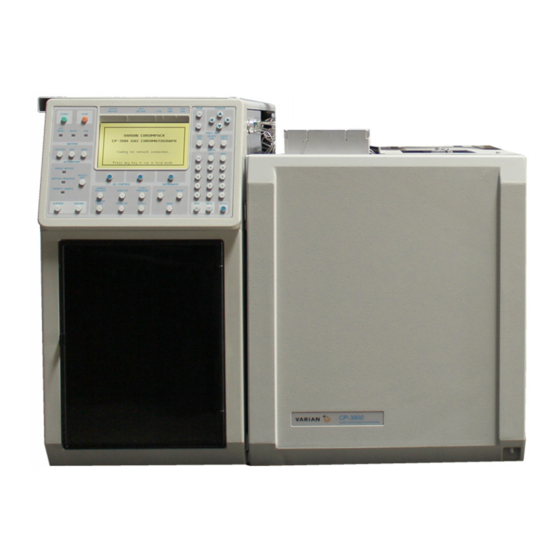
Varian CP-3800 GC Operator's Manual (183 pages)
Brand:
Varian
| Category:
Measuring Instruments
| Size: 4.54 MB
Table of Contents
Table of Contents
4
3800 Keyboard and Display
10
The 3800 Display
10
The 3800 Keyboard
12
PAGE and CURSOR Keys
13
ENTRY Keys
14
INSTRUMENT Keys
15
Setup Parameters
16
Instrument STATUS Key
28
Instrument MENU Key
30
Method
32
Gc Control
36
SAMPLE DELIVERY Key
37
INJECTOR Key
39
Valve Oven
46
FLOW / PRESSURE Key
46
Gas Saver
48
COLUMN OVEN Key
51
DETECTOR Key
52
OUTPUT Key
56
Sample Introduction
58
Liquid Injectors
58
Sampling Valves
58
External Sample Introduction Systems
59
Pneumatic Systems
59
Table 1 Pneumatic Systems for Liquid Injectors and Sampling Valves
59
The CP-1177 Split/Splitless Capillary Injector
60
Features of the CP-1177 Injector
60
Automatic Start Switch
61
CP-1177 Injector Assemblys
61
Figure 1 CP-1177 Injector Assembly
61
CP-1177 Injector Inserts
62
CP-1177 Modes of Injection
62
CP-1177 Flow Diagram
64
Figure 2 CP-1177 Injector Flow Path
64
CP-1177 Pneumatics
65
CP-1177 Electronic Flow Control
65
Figure 3 Type 1 EFC Flow Diagram
65
Operation of the CP-1177 Injector
66
Figure 4 1079 Injector Capillary Installation
66
Table 2 Detector Installation Depths
68
Setting CP-1177 Gas Flow Rates
69
EFC Pneumatics
69
Table 3 Column Ferrule Selection
69
Gas Saver
72
Manual Pneumatics
73
1177 Modes of Operation
74
Table 4 Split Injection Typical Conditions
74
Testing the 1177 Injector Performance
75
Table 5 Splitless Injection Method Parameters
75
The 1079 Universal Capillary Injector
76
Table 6 1177 Test Samples
76
Automatic Start Switch
77
Features of the 1079 Injector
77
1079 Injector Assembly
78
Figure 5 1079 Injector Assembly
78
1079 Injector Inserts
79
1079 Modes of Injection
80
1079 Flow Diagram
82
Figure 6 1079 Injector Flow Path
82
1079 Pneumatics
83
Figure 7 EFC Flow Diagram
83
Figure 8 1079 Injector Capillary Installation
84
Operation of the 1079 Injector
84
Table 7 Detector Installation Depths
86
EFC Pneumatics
87
Setting 1079 Gas Flow Rates
87
Table 8 Column Ferrule Selection
87
Gas Saver
90
Manual Pneumatics
91
1079 Modes of Operation
91
Table 9 Split Injection Typical Conditions
92
Table 10 Isothermal Splitless Injection Method Parameters
93
Table 11 Temperature Ramped Splitless Injection
94
Table 12 On-Column Injection
95
Testing the 1079 Injector Performance
96
Table 13 Large Volume Injection
96
Table 14 1079 Test Samples
96
The 1041 On-Column Injector
97
Automatic Start Switch
97
Injector Assembly and Insert
97
Column Installation
98
Figure 9 1041 Universal Injector with Insert
98
Figure 10 Column Ends
99
Table 15 General Tightening and Retightening for Common Ferrules
100
Table 16 Carrier Gas Flow Rates for 1041
101
1041 Operation
102
Testing the 1041 Injector
103
The 1061 Flash Vaporization Injector
104
Table 17 1041 Test Compounds
104
Table 18 Chromatographic Conditions for Testing the 1041 Injector
104
Automatic Start Switch
105
Figure 11 1061 Flash Vaporization Injector with Insert
105
Injector Assembly and Insert
105
Column Installation
106
Figure 12 Column Ends
107
Table 19 Detector Installation Depths
107
Table 20 General Tightening and Re-Tightening for Common Ferrules
107
1061 Operation
108
Table 21 Carrier Gas Flow Rates for 1061
108
Table 22 1061 Test Compounds
110
Table 23 Chromatographic Conditions for Testing the 1061 Injector
110
Testing the 1061 Injector
110
Valved Systems
111
Detectors
114
Introduction
114
Flame Ionization Detector
114
Initial Set-Up
115
Operation
116
Detector Program
116
Installation/Disassembly
118
Figure 13 FID Exploded View
119
Figure 14 Orientation of Ignitor Probe Elements in FID Tower
121
Figure 15 FID Cross-Sectional View
122
Thermionic Specific Detector
123
Initial Set-Up
123
Operation and Operating Recommendations
123
Figure 16 Structure of Components in the TSD Test Sam*Ple
128
Table 24 TSD Gases, Pressures, Purity, and Flow Rates
129
TSD Assembly
130
Figure 17 TSD Exploded View
131
Figure 18 TSD Cross-Sectional View
134
Thermal Conductivity Detector
135
Initial Set-Up
135
Operation
138
Figure 19 TCD Sensitivity and Amplification
142
Adjust TCD Carrier Gas Flow Rates
144
Electron Capture Detector
146
Initial Set-Up
146
ECD Pneumatics
152
Table 25 ECD Gases, Pressures, Purity, and Flow Rates
152
Installation/Disassembly
153
Figure 20 Cross-Sectional View of the ECD
154
Figure 21 Radioactive Caution Label - Factory Installed
156
Figure 22 Radioactive Caution Label - User Installed
156
Pulsed Flame Photometric Detector
157
Test Chromatograms
158
Communications
164
Introduction
164
Ethernet Communications
164
Figure 23 3800 GC Ethernet Connection
165
Figure 24 10Base2 Ethernet Components
166
Figure 25 3800 GC to Star Workstation Connection
166
Figure 26 Acceptable and Unacceptable Disconnection Examples
167
Figure 27 Complex 3800 GC to Star Workstation Connections
168
Analog Communications
169
Figure 28 Analog Output Connector
169
Local Automation
172
Introduction
172
Figure 29 3800 Local Automation
172
Non-Addressable Automation
173
Addressable Automation
173
Automation Control
174
Automation Methods
175
Single Method, Non-Addressable Automation
176
Method Sequence, Non-Addressable Automation
176
Single Method, Addressable Automation
178
Method Sequence, Addressable Automation
179
8400 Autosampler Control
180
Automation Status
181
Addressable Automation Status Screen (8400 Automation)
181
Non-Addressable Automation Status Screen
182
Advertisement
Varian CP-3800 GC Getting Started Manual (75 pages)
Gas Chromatography
Brand:
Varian
| Category:
Laboratory Equipment
| Size: 0.91 MB
Table of Contents
Table of Contents
3
Introduction
6
Guide to the 3800 User Manuals
6
Finding Information in These Manuals
6
Abbreviations
6
Brief Description of the 3800 Gas Chromatograph
7
Configuration and Options
8
Installation
9
Site Requirements for GC Installation
9
Power Requirements
9
Space Requirements
10
Environmental Requirements
10
Peripheral Connectors
11
GC Installation
12
Inspection
12
Unpacking
12
Remove Protective Devices
12
Connect Data Handling Peripherals
12
Select Gases
13
Install Gas Regulators and Set Pressures
13
Connect Gases
13
Connect GC to Power
14
Turn Power on
14
Factory Default States and Settings
14
Quick Guide to the 3800 Keyboard and Display
15
Getting Around the Keyboard
15
Column Installation and Conditioning
29
Connect Column to Injector
29
Nuts and Ferrules for Capillary Columns
29
Connect Capillary Column to Injector
31
Nuts and Ferrules for Packed Columns
32
Varian Test Column
33
Identify Carrier Gas Controls and Turn on Flow
33
1079 Split Vent Flow and Septum Purge Flow
34
Note for Capillary Column Users
35
Conditioning the Injector and Column
35
Connect Capillary Column to Detector
36
Column Insertion Depths for Varian Detectors
37
Connect Metal Packed Column to Detector
38
Check for Leaks
38
Basic Operation
39
Setting Carrier and Detector Gas Flow Rates
39
Condition the GC System
41
Build a Method to Analyze a Test Sample
41
Method to Analyze a Varian Test Sample on a Varian Test Column
42
Prepare the Test Sample
43
Solvents for GC
43
Sample Volume and Injection Rate
44
Inject the Test Sample
45
Maintenance
46
Overview
46
General GC Maintenance
47
Leak Check
47
Injector Maintenance
51
1079 Injector
52
Remove the Glass Insert
54
Replace the Glass Insert
55
Clean the Glass Insert
56
Deactivate the Glass Insert
57
Injector
58
1041 Injector
59
Hardware Replacement and Cleaning Procedures
59
Septum Replacement
59
Leak Checking
61
Injector
62
1061 Injector
63
Remove the Glass Insert
64
Replace the Glass Insert
64
Clean the Glass Insert
65
Flame Ionization Detector
67
Clean the Flame Tip and Internal Parts
69
Thermionic Specific Detector
69
Cleaning/Maintenance
69
Bead Cleaning
69
Flame Tip and Internal Parts Cleaning
69
Ferrule Replacement
69
Thermionic Specific Detector
70
Electron Capture Detector
71
Thermal Conductivity Detector
72
Pulsed Flame Photometric Detector
72
Micro Thermal Conductivity Detector
72
Parts and Supplies
73
Injector
74
Thermal Conductivity Detector
75
Advertisement
Related Products
Varian Cary 5000
Varian CP-4900 Micro-GC
Varian CP-4900 Pro
Varian CD-91
Varian CD-201
Varian CD-301
Varian CD-451
Varian CP-201
Varian CP-301
Varian 1200 LC/MS
Varian Categories
Water Pump
Controller
Laboratory Equipment
Measuring Instruments
Security Sensors
More Varian Manuals
Login
Sign In
OR
Sign in with Facebook
Sign in with Google
Upload manual
Upload from disk
Upload from URL